boot OPEL GT-R 1973 User Guide
[x] Cancel search | Manufacturer: OPEL, Model Year: 1973, Model line: GT-R, Model: OPEL GT-R 1973Pages: 625, PDF Size: 17.22 MB
Page 299 of 625

6A- 8 1973 OPEL SERVICE MANUAL
Actual adjustment is made by backing off adjusting
nut at the rocker arm until clearance exists between the valve stem, rocker arm, and lifter. Then slowly
tighten adjusting nut until clearance is eliminated.
When clearance is eliminated, turn adjusting nut one
full turn (clockwise). This positions the hydraulic
piston of the hydraulic lifter mid-point in its total
available travel, and no further adjustment is re-
quired.
MAJOR REPAIR
ENGINE ASSEMBLY REMOVAL AND
INSTALLATION
Removal (Opel 1900 and Manta)’
The engine assembly on the Opel 1900 and Manta
can be removed together with the transmission
through the top of the engine compartment.
1. Remove hood (scribe hood hinge to hood mount-
ing location).
2. Disconnect battery negative cable.
3. Drain coolant at lower radiator hose.
4. Remove upper and lower radiator hoses.
5. Remove radiator and fan
shrbud.
6. Disconnect heater hoses.
7. Disconnect brake booster
vacuum hose.
8. Remove air cleaner.
9. Disconnect electrical connections and accelerator
linkage. 10. Remove console.
11. Remove shift lever boot, plate, and shift lever.
12. Raise car on hoist.
13. Disconnect fuel line at pump.
14. Remove front stone shield.
15. Disconnect speedo-cable, back-up light switch,
and clutch cable.
16. Remove drive shaft. I
17. Disconnect exhaust pipe
ar$l bell housing sup-
port.
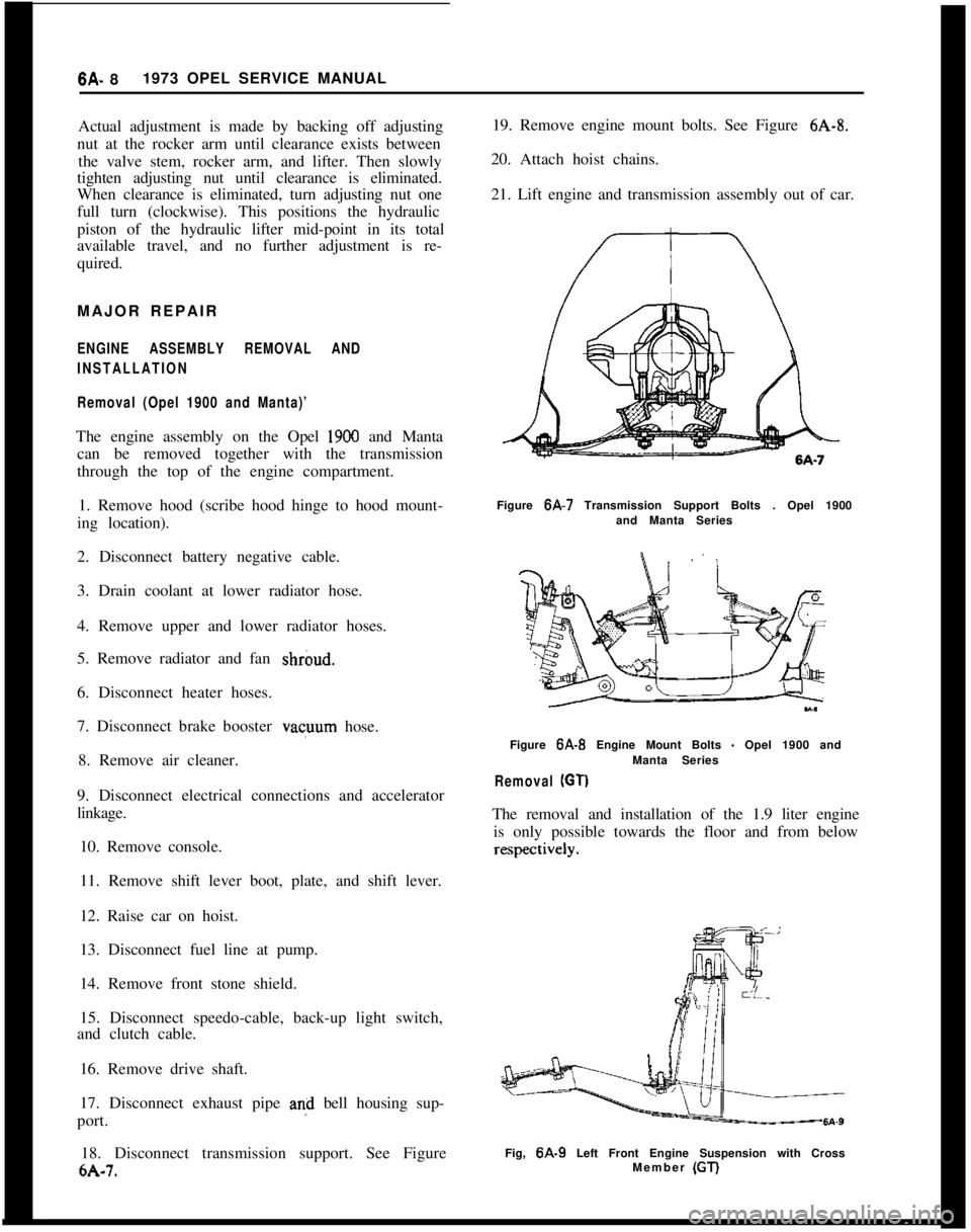
18. Disconnect transmission support. See Figure
6A-7. 19. Remove engine mount bolts. See Figure
6A-8.
20. Attach hoist chains.
21. Lift engine and transmission assembly out of car.
Figure 6A-7 Transmission Support Bolts . Opel 1900
and Manta Series
Figure
6A-B Engine Mount Bolts - Opel 1900 and
Manta Series
Removal (GT)
The removal and installation of the 1.9 liter engine is only possible towards the floor and from below
Fig, 6A-9 Left Front Engine Suspension with Cross
Member (GT)
Page 357 of 625

6G- 661973 OPEL SERVICE MANUAL
6. Check compression of each cylinder. Repeat
compression check and record highest reading ob-
tained on each cylinder during the two pressurechecks.The recorded compression pressures are to be con-
sidered normal if the lowest reading cylinder is more
than 75 percent of the highest reading cylinder. See
the following example and the “Compression Pres-
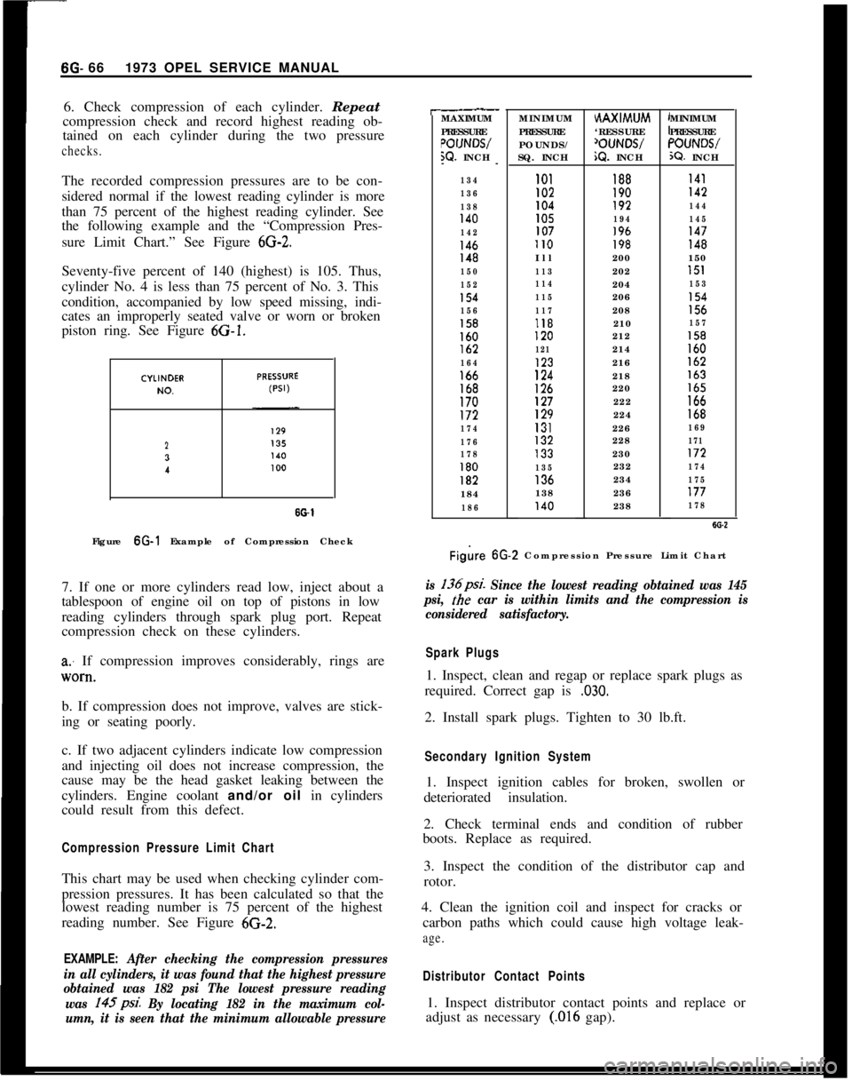
sure Limit Chart.” See Figure
6G-2.Seventy-five percent of 140 (highest) is 105. Thus,
cylinder No. 4 is less than 75 percent of No. 3. This
condition, accompanied by low speed missing, indi-
cates an improperly seated valve or worn or broken
piston ring. See Figure 6G-1.
23
I
SO-1Figure 6G-1 Example of Compression Check
7. If one or more cylinders read low, inject about a
tablespoon of engine oil on top of pistons in low
reading cylinders through spark plug port. Repeat
compression check on these cylinders.
a: If compression improves considerably, rings are
lV0*tl.b. If compression does not improve, valves are stick-
ing or seating poorly.
c. If two adjacent cylinders indicate low compression
and injecting oil does not increase compression, the
cause may be the head gasket leaking between the
cylinders. Engine coolant and/or oil in cylinders
could result from this defect.
Compression Pressure Limit ChartThis chart may be used when checking cylinder com-
pression pressures. It has been calculated so that the
lowest reading number is 75 percent of the highest
reading number. See Figure 6G-2.
EXAMPLE: After checking the compression pressures
in all cylinders, it was found that the highest pressure
obtained was 182 psi The lowest pressure reading
was 145psi.
By locating 182 in the maximum col-
umn, it is seen that the minimum allowable pressure
r-.__MAXIMUM
PRESSURE
POIJNWW. INCH
--
134
136
138
140
142
146148
150
152
154
156
158160lb2
164166168170172
174
176
178
180182184
186MINIMUM
PRESSURE
POUNDS/
SQ. INCHHAXIMUM
‘RESSURE
‘OUNWiQ. INCHMINIMUM
PRESSURE“OUNWX?. INCH
101188I41I02190142104192144105194145107196147II0198148Ill200150
113202151
114204153
115206154
117208156118210157120212158
121214160123216162
124218163
126220165127222166129224168131226169132228171133230172
135232174136234175138236177140238178
Figire 6G.2 Compression Pressure Limit Chart
is 136psi. Since the lowest reading obtained was 145
psi,
the car is within limits and the compression is
considered satisfactory.
Spark Plugs1. Inspect, clean and regap or replace spark plugs as
required. Correct gap is
,030.2. Install spark plugs. Tighten to 30 lb.ft.
Secondary Ignition System1. Inspect ignition cables for broken, swollen or
deteriorated insulation.
2. Check terminal ends and condition of rubber
boots. Replace as required.
3. Inspect the condition of the distributor cap and
rotor.
4. Clean the ignition coil and inspect for cracks or
carbon paths which could cause high voltage leak-
age.
Distributor Contact Points1. Inspect distributor contact points and replace or
adjust as necessary
(.016 gap).
Page 366 of 625

CLUTCH?A- 5MAJOR REPAIR
CLUTCH REMOVAL AND INSTALLATION
Remove Clutch1. Remove transmission. Refer to Manual Transmis-
sion for removal procedure.
2. Remove bolts from engine support brackets, both
sides. Let brackets hang by front bolts.
3. Remove flywheel cover pan.
4. Remove flywheel housing to engine attaching
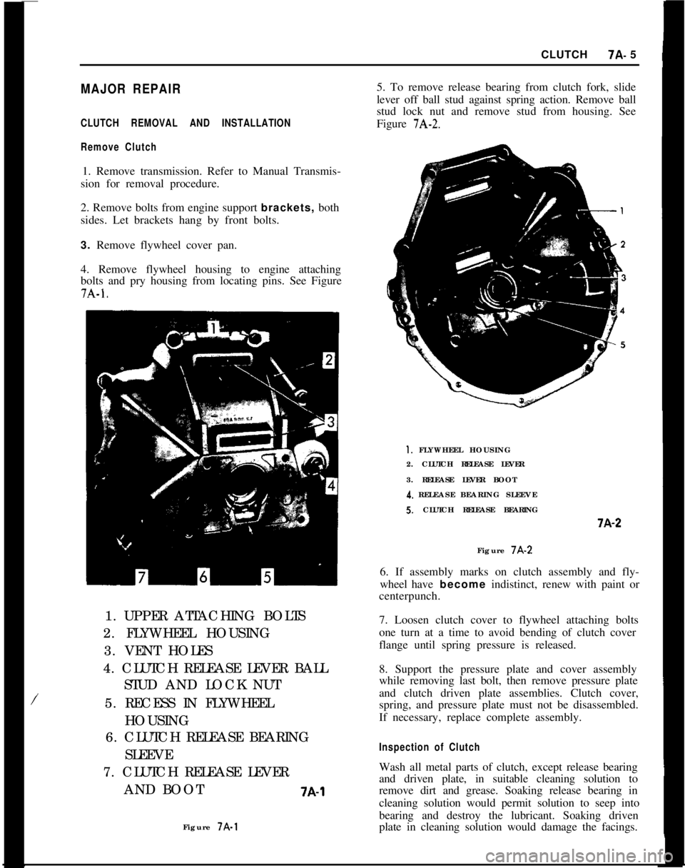
bolts and pry housing from locating pins. See Figure7A-1.
/1. UPPER ATTACHING BOLTS
2. FLYWHEEL HOUSING
3. VENT HOLES
4. CLUTCH RELEASE LEVER BALL
STUD AND LOCK NUT
5. RECESS IN FLYWHEEL
HOUSING
6. CLUTCH RELEASE BEARING
SLEEVE
7. CLUTCH RELEASE LEVER
AND BOOT
7A-1Figure 7A-15. To remove release bearing from clutch fork, slide
lever off ball stud against spring action. Remove ball
stud lock nut and remove stud from housing. See
Figure
7A-2.
1. FLYWHEEL HOUSING
2. CLUTCH RELEASE LEVER
3. RELEASE LEVER BOOT
4. RELEASE BEARING SLEEVES. CLUTCH RELEASE BEARINGi-A-2
Figure 7A-2
6. If assembly marks on clutch assembly and fly-
wheel have become indistinct, renew with paint or
centerpunch.
7. Loosen clutch cover to flywheel attaching bolts
one turn at a time to avoid bending of clutch cover
flange until spring pressure is released.
8. Support the pressure plate and cover assembly
while removing last bolt, then remove pressure plate
and clutch driven plate assemblies. Clutch cover,
spring, and pressure plate must not be disassembled.
If necessary, replace complete assembly.
Inspection of ClutchWash all metal parts of clutch, except release bearing
and driven plate, in suitable cleaning solution to
remove dirt and grease. Soaking release bearing in
cleaning solution would permit solution to seep into
bearing and destroy the lubricant. Soaking driven
plate in cleaning solution would damage the facings.
Page 515 of 625

9A-6 1973 OPEL SERVICE MANUAL
b. Remove retaining screw in headlamp lever handle
and remove handle.c. Console cover is held in place by four push button
type studs, unsnap studs by prying cover up and
work cover upwards over shift lever and rubber shift
lever boot.
5. Remove left cover and right plug in instrument
panel cover and through openitigs remove instru-
ment panel attaching screws (points A and B). See
Figures 9A-7 and 9A-8. At this point it will be neces-
sary to lower the steering column, refer to Group 3
for this procedure.6. Remove two multiple wire plug connectors from
steering column harness.
7. Detach speedo cable
8. Remove
dir&ional signal flasher unit. See Figure9A-9.
Figure
9A-9 Directional Flasher Unit
9. Remove 6 instrument cluster retaining screws. See
Figure 9A-10.
Figure
9A-7 Instrument Panel Cover Screw Cover and
Plug LocationsFigure SA-10 Removing Instrument Cluster detaining
SCWWSFigure
SA-8 Location of Hidden Screws10. Grasp instrument cluster and pull straight back,
being careful of wires, etc. See Figure 9A-11.
11. Unscrew heater controls (A) and support bracket
(B). See Figure 9A-12.
12. Disconnect heater and defroster duct
hoses’frominstrument panel. See Figure 9A-13.
Page 517 of 625

9A-8 1973 OPEL SERVICE MANUAL
Installation
1. Install heater blower and case assembly, securing
with one (1) bolt at the top and two (2) nuts from the
bottom. See Figure
9A-15.
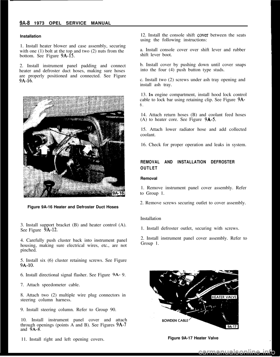
2. Install instrument panel padding and connect
heater and defroster duct hoses, making sure hoses
are properly positioned and connected. See Figure
9A-16.
Figure 9A-16 Heater and Defroster Duct Hoses
3. Install support bracket (B) and heater control (A).
See Figure
9A-12.
4. Carefully push cluster back into instrument panel
housing, making sure electrical wires, etc., are not
pinched.
5. Install six (6) cluster retaining screws. See Figure
9A-10.
6. Install directional signal flasher. See Figure
9A- 9.
7. Attach speedometer cable.
8. Attach two (2) multiple wire plug connectors in
steering column harness.
9. Install steering column. Refer to Group 90.
10. Install instrument panel cover and attach
through openings (points A and B). See Figures
9A-7
and 9A-8.
11. Install right and left opening covers. 12. Install the console shift
cover
between the seats
using the following instructions:
a. Install console cover over shift lever and rubber
shift lever boot.
b. Install cover by pushing down until cover snaps into the four (4) push button type studs.
c. Install two (2) screws under ash tray opening and
install ash tray. 13.
In engine compartment, install hood lock control
cable to lock bar using retaining clip. See Figure
9A-
6.
14. Attach return hoses (B) and coolant feed hoses
(A) to heater core. See Figure
9A-5.
15. Attach lower radiator hose and add collected
coolant.
16. Check for proper operation and leaks in system.
REMOVAL AND INSTALLATION DEFROSTER
OUTLET
Removal
1. Remove instrument panel cover assembly. Refer
to Group 1.
2. Remove screws securing outlet to cover assembly.
Installation1. Install defroster outlet, securing with screws.
2. Install instrument panel cover assembly. Refer to
Group 1.
Figure 9A-17 Heater Valve