dimensions OPEL GT-R 1973 Service Manual
[x] Cancel search | Manufacturer: OPEL, Model Year: 1973, Model line: GT-R, Model: OPEL GT-R 1973Pages: 625, PDF Size: 17.22 MB
Page 320 of 625

ENGINE MECHANICAL AND MOUNTS6A- 29
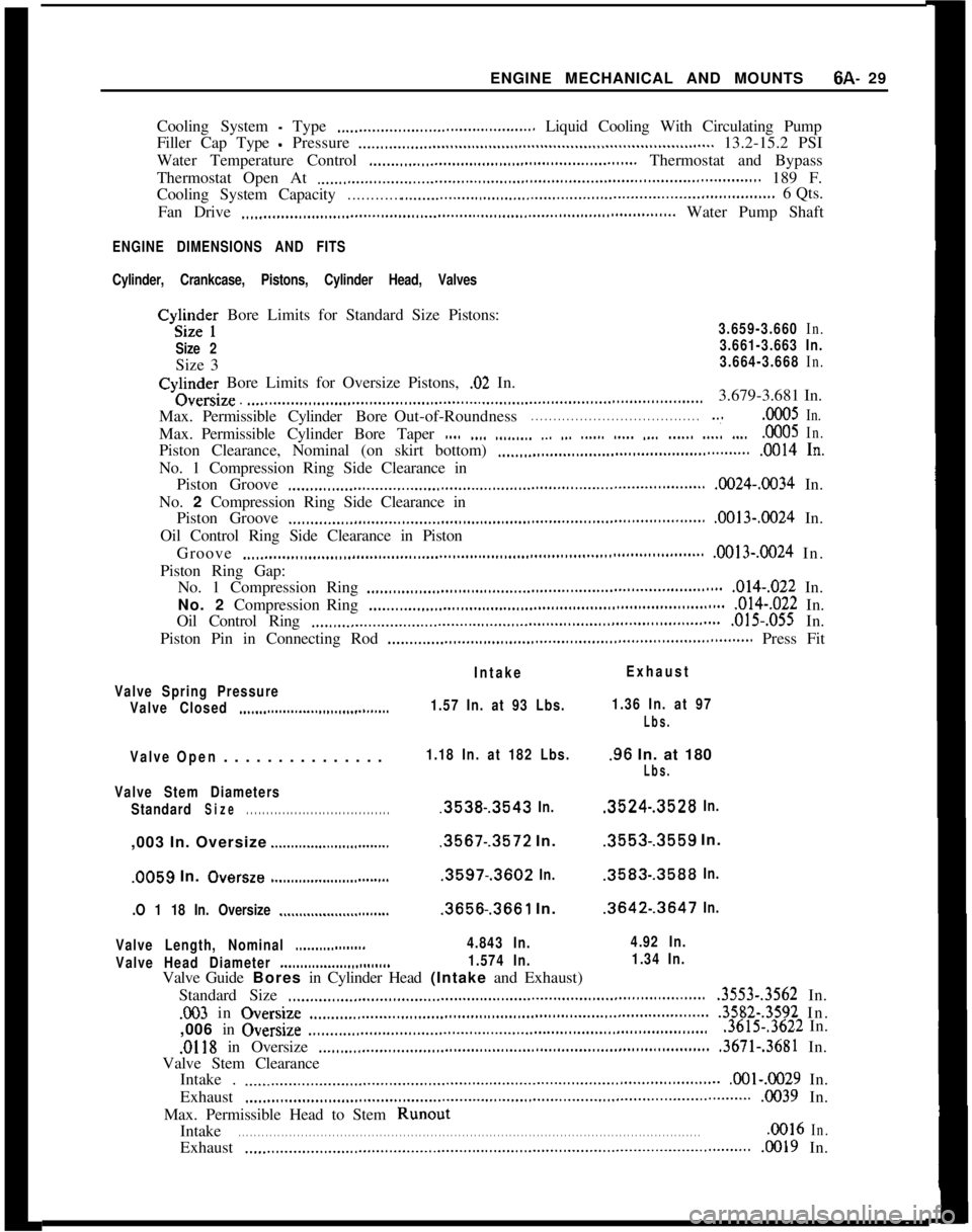
Cooling System - Type ,._...___..___..___........................... Liquid Cooling With Circulating Pump
Filler Cap Type
- Pressure _,._.,,._.,,...,,.........,..,.....,.,.................,,......................... 13.2-15.2 PSI
Water Temperature Control
._,..__,,._.,,__.,,...,.,.,,.,,.,,.,...............,,...,,,... Thermostat and Bypass
Thermostat Open At
._,,.,,.......,__.,.........,,...,...,,..,.,,.,,...................................................... 189 F.
Cooling System Capacity
. . . . . . . . . . . . .._...__..............,,.,,.,,..,...................................,,................6 Qts.
Fan Drive
.,,...,,,....,,.,..,..,,........,..,,..,,,.............,..,,.,..,,.................,,............... Water Pump Shaft
ENGINE DIMENSIONS AND FITS
Cylinder, Crankcase, Pistons, Cylinder Head, Valves
Cyg;te; Bore Limits for Standard Size Pistons:3.659-3.660 In.
Size 23.661-3.663 In.Size 3
3.664-3.668 In.Cylindey Bore Limits for Oversize Pistons,
.02 In.Oversm
. .._............,..,,...,................................,,.,,.,,.........................................3.679-3.681 In.
Max.PermissibleCylinderBoreOut-of-Roundness
. . . . . . . . . . . . . . . . . . . . . . . . . . . . . . . . . . . . . . ..~.OOO5In.Max.Permissible Cylinder Bore Taper
,.., ,.,, ,.,._,__. ,_, ,.. .__... ..__. ,__. .____. ..__. .._..0005In.Piston Clearance, Nominal (on skirt bottom)
_..__,,_.,.___.__.._...........,.......................... .0014 In.No. 1 Compression Ring Side Clearance in
Piston Groove
,...,,,.,,,.,,...,__..........,,..,,...,,...,..,.,,.,,..,,..,,..,,..................,,,..,,,..., .0024-.0034 In.
No. 2 Compression Ring Side Clearance in
Piston Groove
_..,,..,,,..,,..,,..,,....,.......,...,,,.,.,,,..,..,..,,..,,..,,,..,,,.,,,..,,,...,,,..,,,,..., .0013-.OO24 In.
Oil Control Ring Side Clearance in Piston
Groove
__..__..._..,,,..,...,,,..,....,..,,..,.........,..,,...,,.,,.,,..,..,,..,,...,,...,,,..,,,..,,,...,,..... .0013-X024 In.
Piston Ring Gap:
No. 1 Compression Ring
..,,.,,,..,,,..,,..,,,.,,.,,,..,......,,.,..............,......................... .014-,022 In.
No. 2 Compression Ring
_..___..__.,,..,,..,,,..,.,,,..,,.,,....................,......................... .014-,022 In.
Oil Control Ring
,...,,...,___.___.._..................,,,..,..,,..,,.,,,..,,,.,,..,,,..,,,...,,,,..,,,...,.... ,015.,055 In.
Piston Pin in Connecting Rod
..____.___..._,,__.,,,,,..,,.,,..,.................,,............................... Press Fit
IntakeExhaust
Valve Spring Pressure
Valve Closed
_______........___..,,,,,,............1.57 In. at 93 Lbs.1.36 In. at 97
Lbs.
ValveOpen. . . . . . . . . . . . . . .1.18 In. at 182 Lbs..96 In. at 180
Lbs.
Valve Stem Diameters
Standard
Size. . . . . . . . . . . . . . . . . . . . . . . . . . . . . . . . . . . ..3538-.3543 In..3524-.3528 In.,003 In. Oversize
____.....__.._..,,,,,,.........3567-.3572 In..3553-.3559 In..0059 In.
Oversze .__......_______...............3597-.3602 In..3583-.3588 In.
.O 1 18 In. Oversize
_._...._._____...............3656-.3661 In..3642-.3647 In.
Valve Length, Nominal
..___.............4.843 In.4.92 In.
Valve Head Diameter
___.......____...,,,........1.574 In.1.34 In.Valve Guide Bores in Cylinder Head (Intake and Exhaust)
Standard Size
,,...,,...,,..,,..,,,..,,....................................,..,,...,,.,,,,..,,,,..,,...,,,,.., .3553-.3562 In.003 in Oversjze
.,..__,,._.,__..___....,,...,,..,,...,,,,,,.,,.,,..,................,.....,................. .3582-.3592 In.
,006 in Overslze
..,...,,..,,.......................................,.........................................3615-.3622 In.
.0118 in Oversize ,._.,,..,............,,...,,........................................,,.................... .3671-.3681 In.
Valve Stem Clearance
Intake .
.._........___..___.....,............,...,,..........................................,,...................... .OOl-.0029 In.
Exhaust
._.,,........,,...,,..,,...........,,...,................,..,,..,,................,,.....,.,........................ 0039 In.
Max. Permissible Head to Stem Runout
Intake
. . . . . . . . . . . . . . . . . . . . . . . . . . . . . . . . . . . . . . . . . . . . . . . . . . . . . . . . . . . . . . . . . . . . . . . . . . . . . . . . . . . . . . . . . . . . . . . . . . . . . . . . . . . . . . . . . . . . . ..OO16In.Exhaust
.,...........,,...,...,.,,...........,,...,....,....,.,,,..,,.,,,........................................,.......... .0019 In.
Page 365 of 625

7A- 41973 dPEL SERVICE MANUALConditionPossible CauseCorrectionHeat-blued driven plate
and pressure plate
assembly.
1. Improper pedal1. Replace only driven plate, and
adjustment.adjust clutch pedal and cable.
Grab and chatter with
oil present on clutch
assembly.1. Oil leak.1. Correct oil leakage, clean
pressure plate in solvent, replace
driven plate and adjust pedal lash.
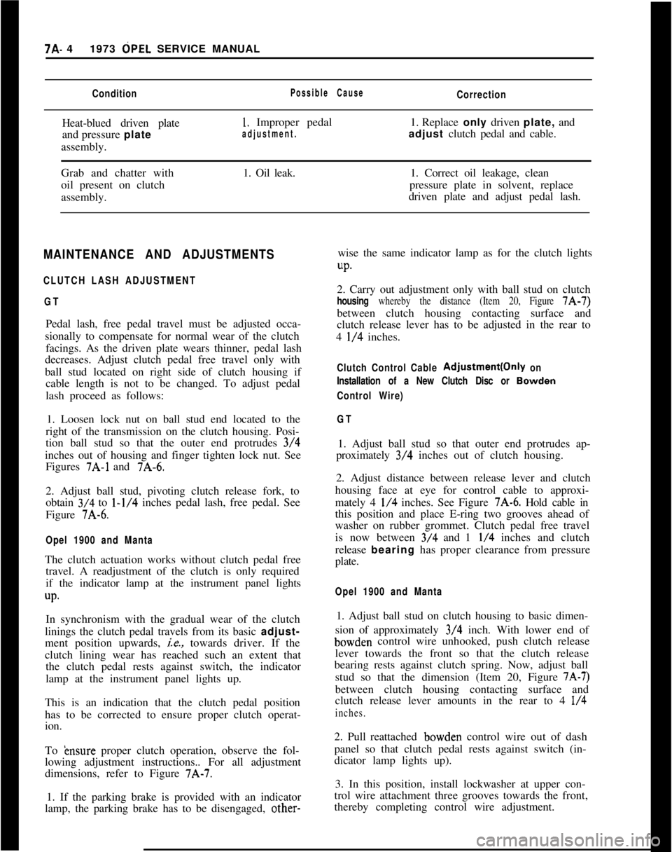
MAINTENANCE AND ADJUSTMENTS
CLUTCH LASH ADJUSTMENT
GTPedal lash, free pedal travel must be adjusted occa-
sionally to compensate for normal wear of the clutch
facings. As the driven plate wears thinner, pedal lash
decreases. Adjust clutch pedal free travel only with
ball stud located on right side of clutch housing if
cable length is not to be changed. To adjust pedal
lash proceed as follows:
1. Loosen lock nut on ball stud end located to the
right of the transmission on the clutch housing. Posi-
tion ball stud so that the outer end protrudes 3/4
inches out of housing and finger tighten lock nut. See
Figures
7A-1 and 7A-6.
2. Adjust ball stud, pivoting clutch release fork, to
obtain 3/4 to
l-1/4 inches pedal lash, free pedal. See
Figure 7A-6.
Opel 1900 and MantaThe clutch actuation works without clutch pedal free
travel. A readjustment of the clutch is only required
if the indicator lamp at the instrument panel lights
up.In synchronism with the gradual wear of the clutch
linings the clutch pedal travels from its basic adjust-
ment position upwards,
ie., towards driver. If the
clutch lining wear has reached such an extent that
the clutch pedal rests against switch, the indicator
lamp at the instrument panel lights up.
This is an indication that the clutch pedal position
has to be corrected to ensure proper clutch operat-
ion.
To
&~sure proper clutch operation, observe the fol-
lowing adjustment instructions.. For all adjustment
dimensions, refer to Figure 7A-7.
1. If the parking brake is provided with an indicator
lamp, the parking brake has to be disengaged, other-wise the same indicator lamp as for the clutch lights
UP.2. Carry out adjustment only with ball stud on clutch
housing whereby the distance (Item 20, Figure 7A-7)
between clutch housing contacting surface and
clutch release lever has to be adjusted in the rear to
4
l/4 inches.
Clutch Control Cable Adjustment(Only on
Installation of a New Clutch Disc or
Bowden
Control Wire)
GT1. Adjust ball stud so that outer end protrudes ap-
proximately 3/4 inches out of clutch housing.
2. Adjust distance between release lever and clutch
housing face at eye for control cable to approxi-
mately 4
l/4 inches. See Figure 7A-6. Hold cable in
this position and place E-ring two grooves ahead of
washer on rubber grommet. Clutch pedal free travel
is now between 3/4 and 1
l/4 inches and clutch
release bearing has proper clearance from pressure
plate.
Opel 1900 and Manta1. Adjust ball stud on clutch housing to basic dimen-
sion of approximately 3/4 inch. With lower end ofbowden control wire unhooked, push clutch release
lever towards the front so that the clutch release
bearing rests against clutch spring. Now, adjust ball
stud so that the dimension (Item 20, Figure
7A-7)between clutch housing contacting surface and
clutch release lever amounts in the rear to 4
l/4
inches.2. Pull reattached bowden control wire out of dash
panel so that clutch pedal rests against switch (in-
dicator lamp lights up).
3. In this position, install lockwasher at upper con-
trol wire attachment three grooves towards the front,
thereby completing control wire adjustment.