tire size OPEL GT-R 1973 Service Manual
[x] Cancel search | Manufacturer: OPEL, Model Year: 1973, Model line: GT-R, Model: OPEL GT-R 1973Pages: 625, PDF Size: 17.22 MB
Page 229 of 625

3G- 621973 OPEL SERVICE MANUAL
1. Clean rims thoroughly, using No. 3 coarse steel
wool to remove all oxidized rubber, soap solution,
etc. Remove rust with wire brush.2. Inspect butt weld and other areas of rim contactedby tire beads to make certain there is no groove or
high spot. Remove any groove or high spot by tiling
smooth.
3. Inspect valve stem and replace it if damaged.
Make certain that valve stem is properly installed to
provide an air tight joint.
4. Before mounting a tubeless tire on a wheel, mois-
ten a cloth with mounting compound or soap solu-
tion and wipe rim-seal ridges of both beads to remove
all foreign substances.
5. Moisten base of both beads with mounting com-
pound or soap solution to help beads snap into place
when tire is inflated. Start tire over rim flange at
point opposite valve stem.
6. Inflate tire until both beads are firmly seated
against rim flanges and temporarily over inflate.
Leak test wheel and tire assembly and if satisfactory,
reduce to recommended pressure.
SPECIFICATIONSWHEEL AND TIRE BALANCE
Wheel and tire balance is the equal distribution of the
weight of the wheel and tire assembly around the axis
of rotation. Wheel unbalance is the principal cause of
tramp and general car shake and roughness and con-
tributes somewhat to steering troubles.
The original balance of the tire and wheel assembly
may change as the tire wears. Severe acceleration,
severe brake applications, fast cornering and side slip
wear the tires out in spots and often upset the origi-
nal balance condition and make it desirable to rebal-
ance the tire and wheel as an assembly. Tire and
wheel assemblies should be rebalanced after punc-
tures are repaired.
Because of the speed at which cars are driven, it is
necessary to test the wheel and tire assembly for
dynamic balance. Dynamic balancing of a wheel and
tire assembly must be done on a machine designed to
indicate out-of-balance conditions while the wheel is
rotating on the car. Since procedures differ with dif-
ferent machines, the instructions of the equipment
manufacturer must be carefully followed.
General SpecificationsWheels
Opel 1900
- Manta and GT ,._......,,,._.................,...,,..............................~,,,.................... 5.J x 13
Tires
1900 - Manta __.......,,___.,...,,..,.....,,....,,...........,...,,.,,...,.........,,..................,....................... 165-13
GT . . . . . . . ..__........_..............,...,,........,,,...,,..........,....,..,,...,,........,..................,,,.....................165-13
Tire Size and Pressures (Pounds Per Square Inch
Cold)
ModelTire Size51.53.54.57
165-1357R.57L165-13
77
165-13Recommended(Standard
PressureInflation)
FrontRear24
PSI32PSI23
PSI26PSI
19PSI23
PSI
NOTE:
1.Tire inflation pressures may increase as much as 6 pounds per square inch
when hot.
2.For continuous high-speed operation (over 75 MPH), increase tire inflation
pressures 4 pounds per square inch over the recommended pressures up to a
maximum of 30 pounds per square inch cool for 4 ply rating tires. When the
4 psi pressure adjustment for sustained high speed with maximum vehicle load
Page 311 of 625

6A. 201973 OPEL SERVICE MANUAL
diameter at the right angle to the piston pin is greater
than the diameter parallel to the piston pin. When a
piston is checked for size, it must be measured with
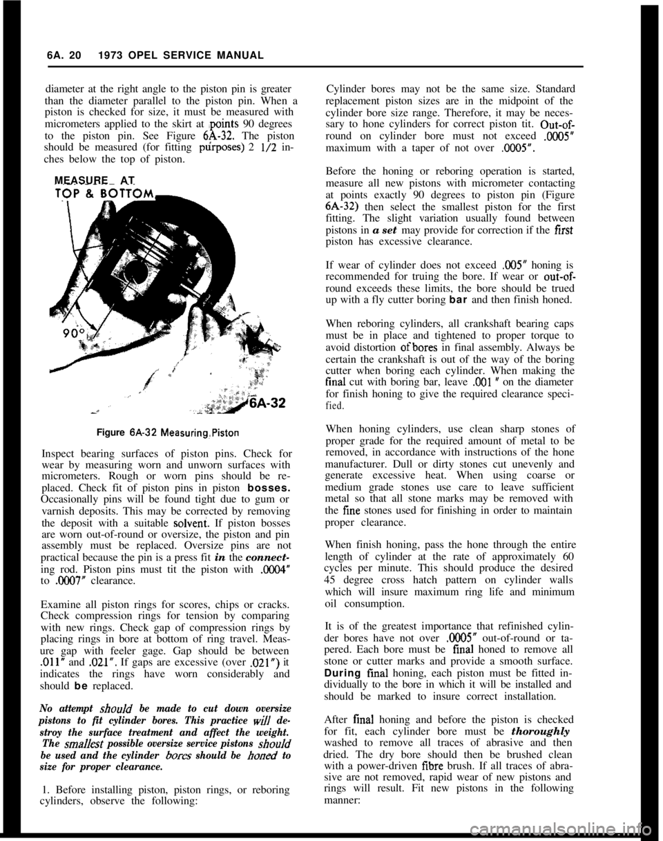
micrometers applied to the skirt at ,points 90 degrees
to the piston pin. See Figure
6A-32. The piston
should be measured (for fitting p&poses) 2
l/2 in-
ches below the top of piston.
MEASURE AT
Figure 6A-32
Measuring,PistonInspect bearing surfaces of piston pins. Check for
wear by measuring worn and unworn surfaces with
micrometers. Rough or worn pins should be re-
placed. Check fit of piston pins in piston bosses.
Occasionally pins will be found tight due to gum or
varnish deposits. This may be corrected by removing
the deposit with a suitable solveni. If piston bosses
are worn out-of-round or oversize, the piston and pin
assembly must be replaced. Oversize pins are not
practical because the pin is a press fit in the connect-
ing rod. Piston pins must tit the piston with
0X4”to
.OCHl7” clearance.
Examine all piston rings for scores, chips or cracks.
Check compression rings for tension by comparing
with new rings. Check gap of compression rings by
placing rings in bore at bottom of ring travel. Meas-
ure gap with feeler gage. Gap should be between
,011” and .02.1”. If gaps are excessive (over .021”) it
indicates the rings have worn considerably and
should be replaced.
No attempt should be made to cut down oversize
pistons to fit cylinder bores. This practice
will de-
stroy the surface treatment and affect the weight.
The
sma/Jest possible oversize service pistons shouId
be used and the cylinder
bores should be honed to
size for proper clearance.1. Before installing piston, piston rings, or reboring
cylinders, observe the following:Cylinder bores may not be the same size. Standard
replacement piston sizes are in the midpoint of the
cylinder bore size range. Therefore, it may be neces-
sary to hone cylinders for correct piston tit. Out-of-
round on cylinder bore must not exceed
.ooO5”maximum with a taper of not over
.OilO5”.Before the honing or reboring operation is started,
measure all new pistons with micrometer contacting
at points exactly 90 degrees to piston pin (Figure6A-32) then select the smallest piston for the first
fitting. The slight variation usually found between
pistons in a set may provide for correction if the first
piston has excessive clearance.
If wear of cylinder does not exceed
.005” honing is
recommended for truing the bore. If wear or
out-of-round exceeds these limits, the bore should be trued
up with a fly cutter boring bar and then finish honed.
When reboring cylinders, all crankshaft bearing caps
must be in place and tightened to proper torque to
avoid distortion ofbores in final assembly. Always be
certain the crankshaft is out of the way of the boring
cutter when boring each cylinder. When making thefinal cut with boring bar, leave
,001 w on the diameter
for finish honing to give the required clearance speci-
fied.When honing cylinders, use clean sharp stones of
proper grade for the required amount of metal to be
removed, in accordance with instructions of the hone
manufacturer. Dull or dirty stones cut unevenly and
generate excessive heat. When using coarse or
medium grade stones use care to leave sufficient
metal so that all stone marks may be removed with
the fine stones used for finishing in order to maintain
proper clearance.
When finish honing, pass the hone through the entire
length of cylinder at the rate of approximately 60
cycles per minute. This should produce the desired
45 degree cross hatch pattern on cylinder walls
which will insure maximum ring life and minimum
oil consumption.
It is of the greatest importance that refinished cylin-
der bores have not over
.0005” out-of-round or ta-
pered. Each bore must be final honed to remove all
stone or cutter marks and provide a smooth surface.
During final honing, each piston must be fitted in-
dividually to the bore in which it will be installed and
should be marked to insure correct installation.
After final honing and before the piston is checked
for fit, each cylinder bore must be thoroughly
washed to remove all traces of abrasive and then
dried. The dry bore should then be brushed clean
with a power-driven iibre brush. If all traces of abra-
sive are not removed, rapid wear of new pistons and
rings will result. Fit new pistons in the following
manner:
Page 485 of 625

7C.1241973 OPEL SERVICE MANUAL
14. Remove the downshift timing valve plug retain-
ing pin and remove downshift timing valve plug.
Remove the low speed downshift timing valve and
spring.
15. Remove the manual low and r&erse control
valve retaining pin. Remove the spring and the
manual low control valve and the reverse control
valve.
16. Remove the l-2 accumulator valve retaining pin
and remove the l-2 accumulator valve plug, l-2 ac-
cumulator valve and spring.
17. A clean work area which is free of dirt and dust
should be used to inspect, clean and install the valves
in the valve body. Handle valve components with
clean hands and tools. Since most valve failures are
caused initially by dirt or other foreign matter pre-
venting a valve from functioning properly, a
thorough cleaning of all the components with a
cleaning solvent is essential. Do not use paraffin toclean out the valve body passages and valve bore.
Compressed air may be used to blow out the pas-
sages.18. Inspect each valve for free movement in its re-
spective bore in
t.he valve body. If necessary, use
crocus cloth to remove small burrs on a valve. Do
not remove the sharp edges of the valves as these
edges perform a cleaning action within the bore.
19. Inspect the valve springs for distortion or col-
lapsed coils. Replace the entire valve body assembly
if any parts are damaged.
20. Inspect the transfer plate for dents or distortion.
Replace transfer plate if necessary.
21. Reassemble the valves, springs, plugs and retain-
ing pins in their proper location and order into the
valve body using a liberal amount of transmission
fluid. See the spring data chart which includes the
spring identification sizes in the event springs have
been disarranged.
LocationApplication
PumpPressureRegulator Valve....................................................
PumpPrimingValve
...........................................................
.............Valve Body1.2ShiftValve......................................................................
Valve Body2-3ShiftValve......................................................................
Valve BodyDetentPressureRegulatorValve......................................
Valve BodyHigh-Speed Timing Valve....................................................
Valve BodyLow-Speed
TimingValve....................................................
Valve BodyReverse and Low Control Valve
........................................
CSSDetentValve..........................................................................
Valve Body1-2 Accumulator Valve........................................................
Valve Body3-2Control
Valve..................................................................
Gov. BodySecondary
Governor Valve................................................
Valve BodyAccumulator Piston
..............................................................
CaseServo Return..........................................................................SHVOServoCushion
........................................................................
Clutch PackClutchReturn(All)................................................................ SPRING IDENTIFICATION CHART
FreeOuter
HeightDiameter
2.756
,7601.043
,3202.467
,7201.769
,7001.625,474
1.349
,4061.380,406
1.343
,4062.569
,6751.072
,5201.853
.4061.317
,4061.9171.224
2.2401.850
1.0391.267
1.050
,42422. Install spring and accumulator piston in valve
body.
23. Compress accumulator piston with C-clamp and
install retaining ring.
24. Install new valve body gasket.2. Inspect and clean oil passages with cleaning sol-
vent and air.
3. Check for good retention of band anchor pins.
25. Bolt the transfer plate and gasket to the valve
body. Torque to 6-8 lbs. ft.
Disassembly, Inspection and Reassembly of Case
1. Inspect case for damage. See Figure
7C-202.4. Inspect all threaded holes for thread damage.
5. Inspect detent valve and modulator valve bores for
scratches or scoring.
6. Inspect case bushing inside of case at rear. If
da-maged, remove bushing with remover and installer
tool J-23 130-3 and driver handle J-8092. See Figure
7C-203.
Page 624 of 625

SubjectPage Number1
Throttle Linkage Adjustment........,:.......6E-51
Timing Chain Cover.......................6A-23
Timing Chain and Sprocket.........
':.......6A-23
Tires...................................36-55
Inflation.....................
.;.......3G-62
Rotation.............................36-57
Sizes.........................
........3G-62
Track Rod..............................3F-53
Transmission Oil Pan
Automatic Transmission.................7C-99
Transmission Reassembly
4 Speed Manual. 1.9.....................76-28Tranmission Removal and Installation
4 Speed Manual
Removal...........................7B-22
Installation.........................76-22
Auto&tic............................7c-94Tune’Up Procedure........................66-65
Torque Specifications. Engine...............6A-27
Turn Signal See Directional Signal
Universal Joints..........................4A-3Subject
VPage Number
Vacuum Modulator..7C-101
Valve Body Transmlssmn7C.99
Valve and Seat Reconditioning Engine6A-12
WWater Pump Engine1.9L Engine
Wheels
Wheel Alignment
Whee! Bearing, Adjustment,
Windshield Wiper and Washer:
Trouble Diagnosis:Description and Operation
Removal and Installation
Specifications
Wiring Diagrams Complete
Opel 1900 ._.
Manta
GT
1 E-37
1 E-37
1 E-38
1 E-43
1 J-l 03
1 J-l 05lJ-10768-3436-553C-223A-4