fuel filter OPEL GT-R 1973 Service Manual
[x] Cancel search | Manufacturer: OPEL, Model Year: 1973, Model line: GT-R, Model: OPEL GT-R 1973Pages: 625, PDF Size: 17.22 MB
Page 16 of 625
LUBRICATION AND MAINTENANCE OC-7SERVICESLUBE AND GENERAL MAINTENANCE
Vehicle operation under conditions such as heavy
dust, continuous short trips, use of other than un-
leaded or low lead fuels or pulling trailers, is not
considered normal use and therefore more frequent
maintenance will be required. Such additional
maintenance requirements are included where appli-
cable.
Engine OilChange each 4 months or
3,COO miles, whichever
occurs first, or each 2 months or
3,ooO miles when
the vehicle is operated under the following condi-
tions: (a) driving in dusty conditions, (b) trailer pull-
ing, (c) extensive idling or (d) short-trip operation at
freezing temperatures (with engine not thoroughly
warmed-up).Engine oils have a definite effect on ease of starting,
oil economy, combustion chamber deposits and en-
gine wear. It is recommended that a” oil which,
according to the label on the can is; (1) intended for
service SE and (2) passes car makers’ tests be used.
Oils confotming to these types contain detergent ad-
ditives. -
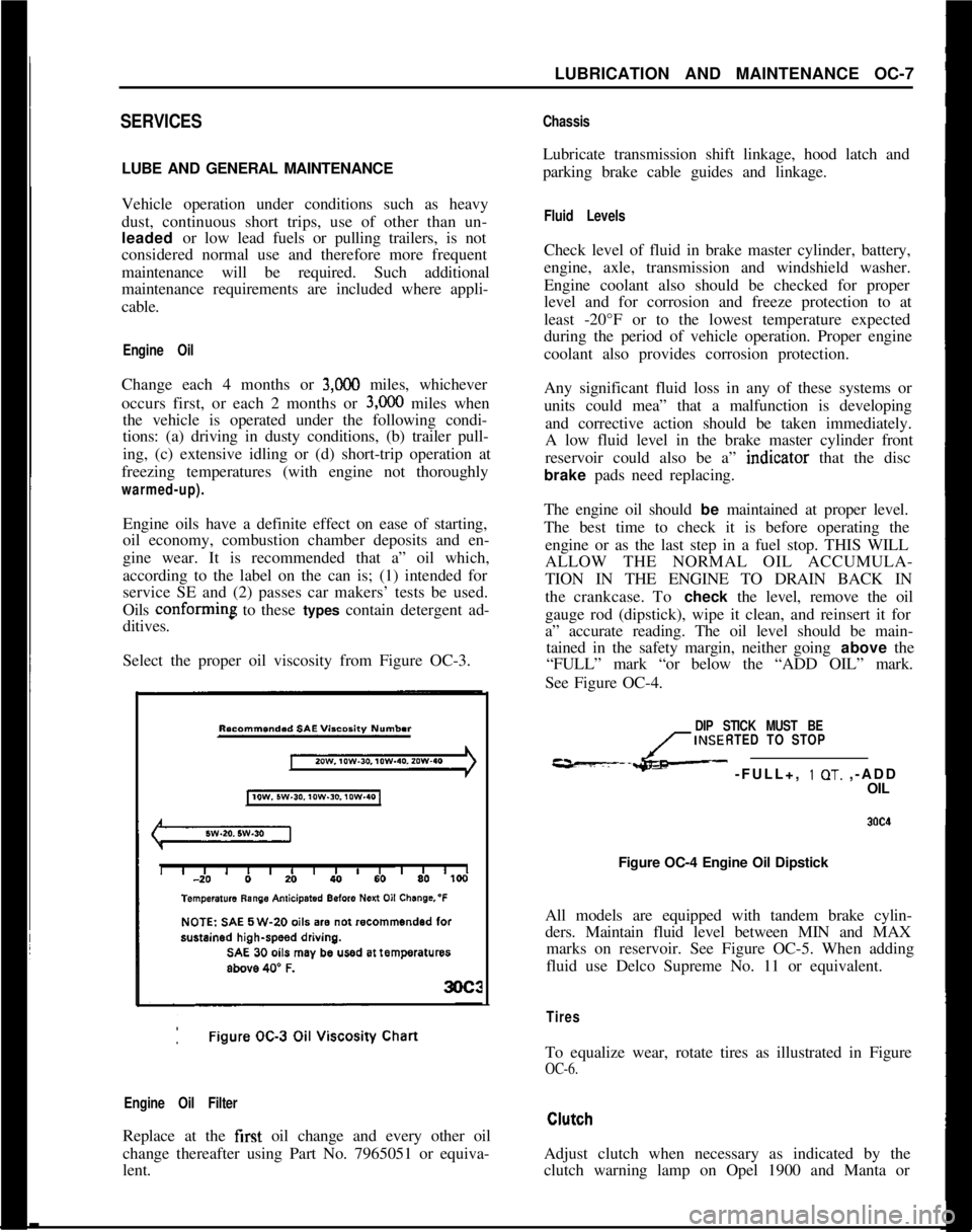
Select the proper oil viscosity from Figure OC-3.
Engine Oil FilterReplace at the first oil change and every other oil
change thereafter using Part No. 7965051 or equiva-
lent.
ChassisLubricate transmission shift linkage, hood latch and
parking brake cable guides and linkage.
Fluid LevelsCheck level of fluid in brake master cylinder, battery,
engine, axle, transmission and windshield washer.
Engine coolant also should be checked for proper
level and for corrosion and freeze protection to at
least -20°F or to the lowest temperature expected
during the period of vehicle operation. Proper engine
coolant also provides corrosion protection.
Any significant fluid loss in any of these systems or
units could mea” that a malfunction is developing
and corrective action should be taken immediately.
A low fluid level in the brake master cylinder front
reservoir could also be a” indtcator that the disc
brake pads need replacing.
The engine oil should be maintained at proper level.
The best time to check it is before operating the
engine or as the last step in a fuel stop. THIS WILL
ALLOW THE NORMAL OIL ACCUMULA-
TION IN THE ENGINE TO DRAIN BACK IN
the crankcase. To check the level, remove the oil
gauge rod (dipstick), wipe it clean, and reinsert it for
a” accurate reading. The oil level should be main-
tained in the safety margin, neither going above the
“FULL” mark “or below the “ADD OIL” mark.
See Figure OC-4.
DIP STICK MUST BE
INSERTED TO STOP
---L- -FULL+, 1 OT. ,-ADD
OIL
Figure OC-4 Engine Oil Dipstick
All models are equipped with tandem brake cylin-
ders. Maintain fluid level between MIN and MAX
marks on reservoir. See Figure OC-5. When adding
fluid use Delco Supreme No. 11 or equivalent.
TiresTo equalize wear, rotate tires as illustrated in Figure
OC-6.Adjust clutch when necessary as indicated by the
clutch warning lamp on Opel 1900 and Manta or
Page 20 of 625
LUBRICATION AND MAINTENANCE OC-11
Throttle Linkage
Check for damaged or missing parts, interference or
binding. Any deficiencies should be corrected with-
out delay.
Headlights
Check for proper aim. Correct as necessary. More
frequent checks should be made if oncoming motor-
ists signal when you are already using your low
beams, or if illumination of the area ‘ahead seems
inadequate.
Underbody
In geographic areas using a heavy concentration of
road salt or other corrosive materials for snow re-
moval or road dust control, flush and inspect the
complete under side of the car at least once each
year, preferably after a winter’s exposure. Particular
attention should be given to cleaning out underbody
members where dirt and other foreign materials may
have collected.
EMISSION CONTROL MAINTENANCE
Thermostatically Controlled Air Cleaner
Inspect installation to make certain that all hoses and
ducts are connected and correctly installed. Also,
check valve for proper operation.
Carburetor Choke
Check choke mechanism for free operation. A bind-
ing condition may have developed from petroleum
gum formation on the choke shaft or from overtight-
ening of air cleaner clamp. Also check electric choke
terminal connections and fuse.
Timing, Dwell and Distributor
Adjust timing and dwell accurately as outlined under
Tune-Up in Group 6 at the first 4 months or 6,ooOmiles of operation, then at 12 month or
12,OQO mile
intervals. Adjustments must be made with test equip-
ment known to be accurate.
Replace distributor points every 12 months or 12,000
miles and carefully clean and inspect the complete
distributor cap to prevent misfiring and deteriora-
tion.
Carburetor and Idle
SpeedTorque carburetor attaching bolts and/or nuts to 12
ft.lbs. to compensate for compression of gasket atiirst 4 months or 6,000 miles of vehicle operation.Adjust idle speed to specifications with known accu-
rate equipment.
Proper functioning of the carburetor is particularly
essential to control of emissions. Correct mixtures
for emission compliance and idle quality have been
preset by Opel. Plastic idle mixture limiters have
been installed on the idle mixture screw, idle air
screw, and throttle stop screw to preclude unauthor-
ized adjustment. The plastic caps on the idle mixture
screw and the idle adjustment screw must be
removed to perform an idle speed adjustment. The
plastic cap on the throttle stop screw is not to be
removed unless some major carburetor repair or re-
placement which affects the throttle stop screw ad-
justment has been necessary.
Carburetor Fuel Inlet Filter
Replace filter at 12 month or
12,OCO mile intervals
or more often if clogged.
Spark Plugs
Replace at
6,ooO mile intervals when operating with
leaded fuels or at 12,000 mile intervals when using
unleaded fuels. Use of leaded fuels results in lead
deposits on spark plugs and can cause misfiring at
mileages less than
12,OilO miles. Where misfiring oc-
curs prior to
6,ooO miles, spark plugs in good condi-
tion can often be cleaned, tested and reinstalled in an
engine with acceptable results.
Spark Plug Wires
Inspect spark plug wires for evidence of checking or
cracking of exterior insulation and tight fit in the
distributor cap and at the spark plugs. Exterior of
wires should be cleaned, any evidence of corrosion
on ends removed and wire replace if deteriorated.
Positive Crankcase Ventilation System
The PCV metered orifice should be cleaned at 12,000
mile intervals under normal use, and at 6,000 mile
intervals when the vehicle is used under the follow-
ing conditions: driving in dusty conditions, extensive
idling, trailer pulling and short trip operation at
freezing temperatures (engine not thoroughly
warmed-up).
Evaporation Control System
Check all fuel and vapor lines and hoses for proper
connections and correct routing as well as condition.
Remove canister and check for cracks or damage.
Replace damaged or deteriorated parts as necessary.
Replace filter in open end of canister at 24month/24,000 mile intervals.
Page 328 of 625
FUEL SYSTEMSC- 37
must always be removed before the distributor can be
removed.
EVAPORATION CONTROL SYSTEM1. The function of the fuel evaporation control sys-
tem is to absorb the fuel vapors developing in the fuel
tank, especially when vehicle is parked, due to at-
mospheric pressure and temperature influences, and
to release these fuel vapors during vehicle operation.
2. This system utilizes the property of the activated
carbon to absorb and expel fuel vapors. The activated
carbon container is installed on the left front side of
the engine compartment. The fuel tank has a
non-vented tiller cap. Vent hoses are joined in the area of
the tank. A plastic evaporation line leads from there
along vehicle underbody to the activated carbon con-
tainer.
3. A small tube above the throttle valve body con-
nects the carburetor to the activated carbon con-
tainer. In this way, the fuel vapor collected in the
activated carbon container is fed through the carbu-
retor into the combustion chambers during engine
operation.
4. The carburetor is provided with an internal and
outside ventilation, the activated carbon container is
also connected to the outside ventilation (only effec-
tive when engine is idling). In this way, the fuel
vapors escaping to the outside during engine idle are
collected by the activated carbon container and fed
into the combustion chambers.
5. The vent lines are connected to the upper part of
the activated carbon container. Fresh air enters
through a foam rubber filter at the lower part andflows, together with the fuel vapor, to the carburetor.
Metered bores in the hose fittings of the fuel tank
control the air
- and fuel vapor flow through the
activated carbon container to the carburetor, and the
pressure release in the fuel tank and ensure complete
purging of the carbon container.
Care must be taken not to mix up lines at the ac-
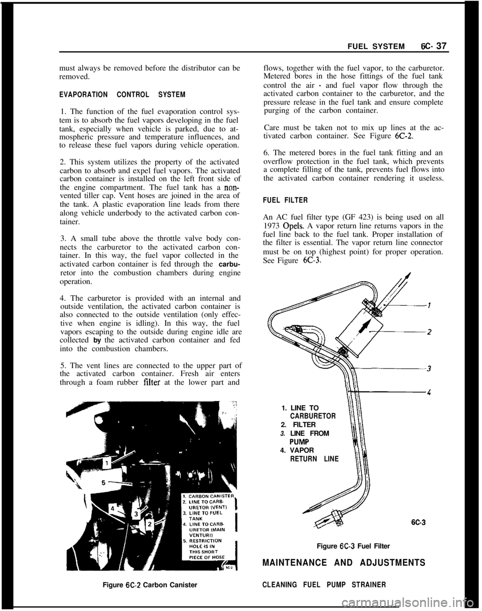
tivated carbon container. See Figure
6C-2.6. The metered bores in the fuel tank fitting and an
overflow protection in the fuel tank, which prevents
a complete filling of the tank, prevents fuel flows into
the activated carbon container rendering it useless.
FUEL FILTERAn AC fuel filter type (GF 423) is being used on all
1973 Opels. A vapor return line returns vapors in the
fuel line back to the fuel tank. Proper installation of
the filter is essential. The vapor return line connector
must be on top (highest point) for proper operation.
See Figure
6C-3.1. LINE TO
CARBURETOR2. FILTER
3. LINE FROM
4. VAPOR
RETURN LINE
6C-3Figure
6C-3 Fuel Filter
MAINTENANCE AND ADJUSTMENTSFigure
6C-2 Carbon CanisterCLEANING FUEL PUMP STRAINER
Page 329 of 625
6C- 381973 OPEL SERVICE MANUALCAUTION:Because the fuel pump is below fuel tank
level, fuel
will drain from the tank. when the supply
hne is disconnected from the fuel pump.1. Pull fuel supply line and rubber connector from
fuel pump. Plug rubber connector to prevent fuel
loss.2. Remove fuel pump cap, gasket and plastic
strainer.
3. Cover center opening in sediment bowl with finger
and blow out sediment bowl with compressed air.
4. Wash plastic strainer in solvent; if strainer does
not clean-up or is damaged, replace strainer.
5. Install clean parts, noting the following:
(a) Strainer must be properly seated with projections
facing upward.(b) A new cap gasket must be positioned over
strainer.
(c) Sealing ring must be in place on cap retaining
screw.6. Reconnect fuel supply line. Start engine and check
for leaks.
EVAPORATION CONTROL SYSTEMProper performance of the system requires the use of
a non-vented fuel tank cap, hose connections be leak-
free, and all hoses routed correctly to avoid a
pinched or blocked line.
Maintenance requirements demand only that the ac-
cumulator purge air tilter, an oiled foam filter assem-
bled in the bottom of the canister, be replaced at
12,CKO mile intervals. Under extremely dusty condi-
tions, more frequent attention may be required.
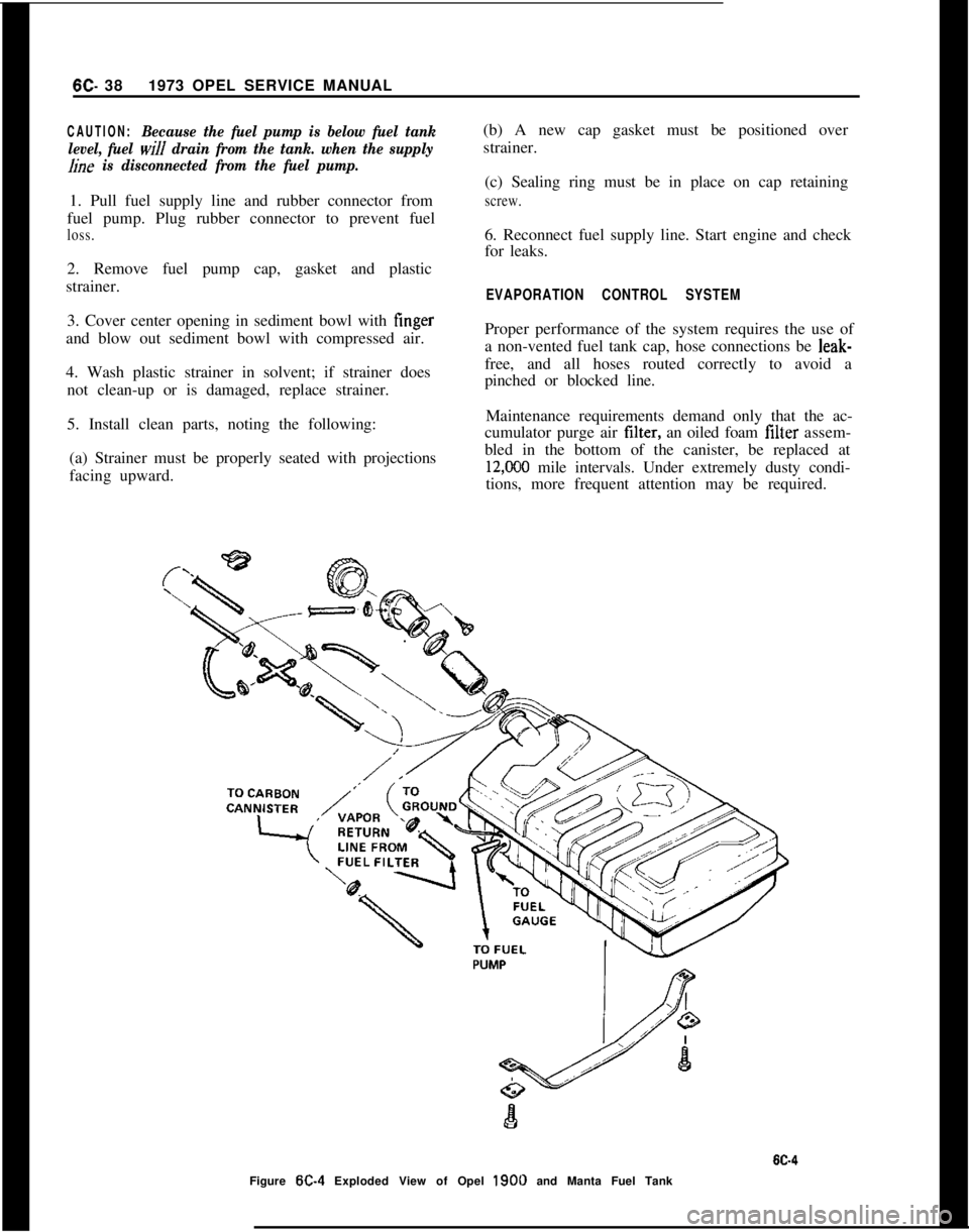
Figure
W-4 Exploded View of Opel 1900 and Manta Fuel Tank
Page 332 of 625
FUEL SYSTEM6C- 41
covered with sound deadening compound. See Fig-
ure
6C-10.7. Remove fuel tank vent hose and tiller hose. See
Figure 6C- 11.
8. Remove fuel tank attaching bolts and gauge wire
and remove tank.
Installation
1. Install tank and tighten attaching bolts.
2. Replace gauge wire. Install vent hose, making cer-
tain it is not kinked and seal vent hose hole in floor.
3. Install spare tire support attaching brackets, sup-
port panel, hold-down, and brackets.
4. Install spare tire and jack.
5. Install fuel line and rubber cap.
6. Connect battery.FUEL LINES. FUEL GAUGE TANK UNITS
All fuel lines are plastic and have an outside diameter
of
,240 inches. Unlike metal lines, plastic lines are
not flared.
When replacing a plastic line, place the line in hot
water to make it flexible. Using the old line as a
pattern, form the new line. Let the line cool com-
pletely, then route it in the same location as the old
line. To prevent chafing against the underbody, nine
(9) rubber grommets are placed at points on the line
between the fuel tank and the fuel pump. When re-
placing fuel gauge tank units, coat gasket on both
sides and first threads of attaching screws with seal-
ing compound.
CLEANING FUEL TANK
1. Remove fuel tank.
2. Empty fuel tank through filler neck.
3. Remove fuel gauge tank unit, together with suc-
tion tube and screen. Clean screen and blow out from
cover side. Flush fuel tank.
SPECIFICATIONSFuel Tank Capacity (Gallons)
Opel 1900 and Manta
....................................................................................................11.9GT
....................................................................................................................................13.2FuelGaugeType
........................................................................................................Electrical
Fuel Pump Type
......................................................................................................Mechanical
Fuel Pump Drive
..................................................................................Eccentric on Camshaft
Fuel Pump Pressure at 1950 (RPM)................................................................3.1 to 3.7 P.S.I.FuelFilter
............................................................................................................In-LineFilter
Page 349 of 625
6E- 581973 OPEL SERVICE MANUAL
Figure 6E-34 Leaf Spring Installed
1 6E-36
Figure 6E-36 Checking Vent Valve Adjustment
39. Check compression of vent valve lower spring. It
should be compressed
l/4 inch with throttle valve
completely closed. See Figure
6E-36.40. Correct by bending valve lever.
Figure
6E-35 Installing Cover Gasket
SPECIFICATIONS
GENERAL SPECIFICATIONSCompression Ratio
........................................................................................................7.6 to 1
Fuel Required
................................(...........................................................................Low Lead
Fuel Tank Capacity (Gallons)
Opel1900andManta..
....................................................................................................11.9
GT...................................................................................................................................13.2Fuel Gauge Type
........................................................................................................Electrical
FuelPumpType
......................................................................................................Mechanical
FuelPumpDrive
..................................................................................EccentriconCamshaft
Fuel Pump Pressure at 1950 RPM
......................................................................3.1 to 3.7 psi
FuelFilter
............................................................................................................In-LineFilter
CarburetorMakeandType................................................I-Solex2BBLAutomaticChoke
AirCleanerElementType
..........................................................................FiberMesh-Paper
Page 358 of 625
2. If inspection of contact points indicates excessive
burning, pitting or wear, check condenser and re-
place if necessary.
3. Inspect all connections and wires in the primary
ignition circuit. Correct any abnormal conditions
found.Carburetor1. Clean fuel strainer in fuel pump. To prevent fuel
leakage in pump, disconnect “IN” line from pump
and raise end above fuel level. The in-line fuel filter
should be replaced every 12,000 miles or every 12
months.
2. Check for freedom of choke valve operation and
clean shaft if necessary, with suitable solvent.
3. Inspect throttle cable or linkage bracket and re-
turn spring for wear. With helper depressing acceler-
ator pedal to floor, check for wide open throttle.
Adjust accelerator pedal height so wide open throttle
is obtained when pedal is within
l/2 inch from floor.
Lubricate linkage pivot points with engine oil.
Air CleanerCheck paper element every 6,000 miles and replace
every
24,ooO miles. If a vehicle is operated in dusty
territory, check condition of air cleaner element
more frequently and replace if necessary.
Fan Belt1. Inspect belt for wear, cracks or frayed points.
Replace and/or adjust as necessary. Specified ten-
sion for belt using Gauge J-23600 is 45 lbs.
Cooling System1. Inspect the radiator, water pump, cylinder head
areas and all radiator and heater hose connections
for evidence of engine coolant leaks.
2. Inspect all hoses for deterioration from gas and oil
contact. Correct as required.
Inspection should be made with engine operating at
normal temperature, cooling system completely
filled, temperature control lever fully open and nor-
mal pressure in the system. Normal pressure should
be 13.2 to 15.2 psi.
Engine Lubrication SystemInspect engine for evidence of oil leakage. Correctany abnormal condition with sealastic or new seals
and gaskets.
Battery
1. Inspect battery, battery mount and cables and
check electrolyte level. Proper level should be just
above the cell plates.
CAUTION:Do not over fill.
2. Determine the serviceability of the battery by ap-
plying the 421 Battery Test.
Positive Crankcase VentilationClean crankcase ventilator metered orifice in the in-
take manifold fitting every 6,000 miles. Also all hoses
and fittings should be inspected, cleaned and re-
placed, if necessary.
To clean, remove rubber hose from metered orifice
and apply air pressure to orifice to remove any for-
eign particles that may be trapped.
Valve Lifter AdjustmentRefer to Engine Mechanical and Mounts section for
valve lifter adjustment procedure.
Engine Tune-Up Instrument ChecksThe following instrument checks and adjustments
serve as a final check on engine condition. These
checks may discover some new problems that may
not have been obvious before. The engine is also
given its final adjustments that will assure maximum
performance, reliability, and proper emission con-
trol.
Refer to Electrical Group for checking procedures of
the following:
Cranking Voltage Check
Ignition Timing
Distributor Advance
Ignition Output
Secondary Resistance
Current Output and Voltage Setting
Idle Speed and Mixture AdjustmentsRefer to carburetor section.
Page 622 of 625

Subject
Page NumbelSubjectPage Number4.Speed Manual I..
Clutch
Detent Cable Adjustment
:Differential
Directional Signal Switch
Repair Opel 1900 & Manta
Repair GT
:Disassembly of
4.Speed Manual Transmission
DistributorFunction of Valves and Hydraulic Control Units
Opel
3.Speed Automatic.................
74-21
Fuse Chart..............................lG-56
Fusible Link.............................
lA-8Specifications.
Point Replacement..
..,78-127A-
17c-9148-73E-393E-4878.23
1C-26
1 c-20
GEGas Tank See Fuel Tank
General Specifications
Engine...............................6A-28
Opel 3.Speed Automatic
.................7C-134
Transmission, Manual.,
..................78-33
Clutch...............................7A-7
Body................................ZA-4
Governor Drive Gear
Opel
3.Speed Automatic.................7C-103
Grille
Opel 1900 & Manta.....................8A-7
GT..................................8A-6 Electrically Heated Rear Window
Engine
General Description
Cooling System
Lubrication System
Trouble Diagnosis
Exhaust Manifold
Exhaust System
Removal and Installation
External Oil Leaks,
Opel 3 Speed Automatic
FFast Idle Adjustment
..................
Filter-Engine Oil
......................
Fluid Checking Procedure Transmission
Opel 3Speed Automatic.............
Frame-Opel 1900 & Manta.............
Frame
GT-Opel......................
SWVOOpel Xipeed Automatic...........
Front Suspension
Opel1900&Manta.................
GT..............................
Front Wheel Alignment................
Front Wheel Bearing Adjustment
All Series.........................
Fuel Gauge
Trouble Diagnosis
Opell$OO&Manta...............
GT............................
Fuel Pump Operation..................
Fuel System
Fuel Tank (Opel 1900 & Manta)
.......
Fuel Lines (Opel 1900 & Manta)
.......
Fuel Tank
(GT)....................
Fuel Gauge Tank Unit
(GT)...........
Fuel Lines
(GT)....................
Fuel Tank Removal and Installation....
Cleaning Tank.....................
lH-576A-268-326A-46A-66A-126D-427C-816E-51
oc-77C~Bl2B-826-77c-1003A-23A-23C-223A-4
HHazard Warning Flasher
....................lG-55
Headlamp Aiming
.........................1 F-46
Headlamp Switch
Opel 190.0 & Manta
.....................1 F-46
Headlamp Mechanism GT
..................8A-2
Heater System Opel 1900 &Manta
Trouble Diagnosis
......................9A-11
Description and Operation
................9A-10
Adjustments and Minor Service............9A-12
Removal and Installation
.................9A-12
Specifications..........................$A-16
Heater System GT
Trouble Diagnosis
......................9A-4
Description and Operation
................9A-2
Adjustments and Minor Service
............9A-4
Removal and Installation.................9A-5
Specifications..........................$A-9Horn
Operation.............................lG-54
Hydraulic Operation
Opel
3.Speed Automatic.................7C-64
IIdentification Number Vehicle...............
OA-1ldle.Adjustment
..........................6E-51
Inflation Pressures, Tires.
...................36-62
Ignition Coil
Specifications.
.........................
lC-26Identification, Engine
......................
OA-1Ignition System
Timing...............................
lC-20Instrument Panel Parts Removal