oil viscosity OPEL GT-R 1973 Service Manual
[x] Cancel search | Manufacturer: OPEL, Model Year: 1973, Model line: GT-R, Model: OPEL GT-R 1973Pages: 625, PDF Size: 17.22 MB
Page 16 of 625
LUBRICATION AND MAINTENANCE OC-7SERVICESLUBE AND GENERAL MAINTENANCE
Vehicle operation under conditions such as heavy
dust, continuous short trips, use of other than un-
leaded or low lead fuels or pulling trailers, is not
considered normal use and therefore more frequent
maintenance will be required. Such additional
maintenance requirements are included where appli-
cable.
Engine OilChange each 4 months or
3,COO miles, whichever
occurs first, or each 2 months or
3,ooO miles when
the vehicle is operated under the following condi-
tions: (a) driving in dusty conditions, (b) trailer pull-
ing, (c) extensive idling or (d) short-trip operation at
freezing temperatures (with engine not thoroughly
warmed-up).Engine oils have a definite effect on ease of starting,
oil economy, combustion chamber deposits and en-
gine wear. It is recommended that a” oil which,
according to the label on the can is; (1) intended for
service SE and (2) passes car makers’ tests be used.
Oils confotming to these types contain detergent ad-
ditives. -
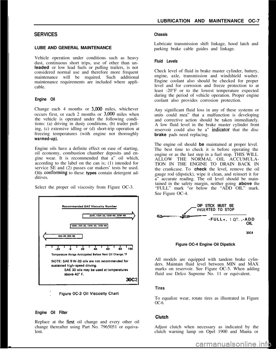
Select the proper oil viscosity from Figure OC-3.
Engine Oil FilterReplace at the first oil change and every other oil
change thereafter using Part No. 7965051 or equiva-
lent.
ChassisLubricate transmission shift linkage, hood latch and
parking brake cable guides and linkage.
Fluid LevelsCheck level of fluid in brake master cylinder, battery,
engine, axle, transmission and windshield washer.
Engine coolant also should be checked for proper
level and for corrosion and freeze protection to at
least -20°F or to the lowest temperature expected
during the period of vehicle operation. Proper engine
coolant also provides corrosion protection.
Any significant fluid loss in any of these systems or
units could mea” that a malfunction is developing
and corrective action should be taken immediately.
A low fluid level in the brake master cylinder front
reservoir could also be a” indtcator that the disc
brake pads need replacing.
The engine oil should be maintained at proper level.
The best time to check it is before operating the
engine or as the last step in a fuel stop. THIS WILL
ALLOW THE NORMAL OIL ACCUMULA-
TION IN THE ENGINE TO DRAIN BACK IN
the crankcase. To check the level, remove the oil
gauge rod (dipstick), wipe it clean, and reinsert it for
a” accurate reading. The oil level should be main-
tained in the safety margin, neither going above the
“FULL” mark “or below the “ADD OIL” mark.
See Figure OC-4.
DIP STICK MUST BE
INSERTED TO STOP
---L- -FULL+, 1 OT. ,-ADD
OIL
Figure OC-4 Engine Oil Dipstick
All models are equipped with tandem brake cylin-
ders. Maintain fluid level between MIN and MAX
marks on reservoir. See Figure OC-5. When adding
fluid use Delco Supreme No. 11 or equivalent.
TiresTo equalize wear, rotate tires as illustrated in Figure
OC-6.Adjust clutch when necessary as indicated by the
clutch warning lamp on Opel 1900 and Manta or
Page 297 of 625
6A. 61973 OPEL SERVICE MANUALDIAGNOSIS
EXCESSIVE OIL CONSUMPTION
ConditionCorrectionExternal Oil Leaks at:Tighten attaching bolts. If leaks
Rocker Arm Coverspersist, remove cover (or pan),
Crankcase Front Covercheck sealing surfaces for burrs
Oil Pan and Gasketor scoring, replace gasket, and
seal bolts with silastic sealer or
equivalent. Make sure oil level
,is not overfull.
Improper Reading of Dip-Car may not be level when taking r
StickInsuffIcient oil “drain-back” time
after stopping engine (three
minutes must be allowed). Dip-
stick may not be completely pushed
down against stop. Dipstick may
be bent.
Oil Viscosity Too LightUse recommended SAE viscosity for
prevailing temperatures.
Continuous High-SpeedAt speeds above 60 mph, increased
Drivingsumption can be expected with any
Inform customer of this fact.
High-Speed DrivingWhen principal use of automobile i
Following Normal Slowcity driving, crankcase dilution f
Speed City Drivingcondensation occurs. High speed a
temperatures will remove water,
resulting in what appears to be
rapid lowering of oil level.
Inform customer of this fact.
Piston Rings NotAllow engine to accumulate at leas
“Broken In”
4,OCO miles before attempting any
engine disassembly to correct for
oil consumption.
NOISY VALVES AND LIFTERSIf the preceding check indicates valve mechanism is
abnormally noisy, remove the rocker arm cover so
that the various conditions that cause noise may be
The noise level of the valve mechanism cannot bechecked. A piece of heater hose of convenient length
properly judged where the engine is below operatingmay be used to pick out the particular valves or valve
temperature when the hood is raised, or when thelinkages
thit are causing abnormal noise. With the
valve rocker arm covers are removed.engine running at a speed where the noise is pro-
nounced; hold the end of hose to an ear and hold
Before attempting to judge valve noise level, the en-other end about
l/2 inch from point of contact be-
gine must be thoroughly warmed up (at least 20tween rocker arm and valve stem. Mark or record the
minutes of operation at
1200 to 1500 RPM) to stabil-noisy valves for investigation of following causes:ize oil and coolant temperatures and bring all engine
parts to a normal state of expansion. When the
en-1. Sticking, Warped, or Eccentric Valves, Worngine is warmed up, listen for engine noise while
sit-Guides Sticking valves will cause irregular engine
ting in the driver’s seat with the hood closed. Run theoperation or missing on a low speed pull and will
engine at idle and at various higher speeds.usually cause intermittent noise.
Page 556 of 625
REFRIGERANT COMPONENTS ALL MODELS9a- 47
B. Connect center flexible line of gauge set to the
fitting on the valve.
C. Start engine, turn temperature control knob to full
cold position, set blower switch to Max Hi. Operate
engine for 10 minutes at 2000 RPM to stabilize sys-tem.D. With compressor operating, slowly open valve on
refrigerant can and allow refrigerant to flow into
system (through manifold gauge set) until liquid in-
dicator clears up and immediately shut off valve at
gauge set and on refrigerant can. Check weight of
can and valve assembly and record.
E. Add an additional 1 lb. of refrigerant by adding
refrigerant from the can just weighed until can is
empty. Attach another can and add refrigerant until
can and valve assembly weigh the same as recorded.
6. Close valves at refrigerant drum or
can,7. Test for leaks and make operational check of
system.
ADDING OIL TO THE SYSTEM (MAJOR
OVERHAUL)The oil in the refrigeration system does not remain
in the compressor during system operation, but cir-culates throughout the system. The compressor is
initially charged with 10 oz. of 525 viscosity oil.
After system has been in operation the oil content in
the compressor will vary depending on the engine
RPM and air conditioning load. At higher engine
RPM’s a lesser amount of oil will be retained in the
compressor reservoir. It is important that the total
system oil content does not vary from a total of10-l/2 oz. Excessive oil content will reduce cooling
capacity. Inadequate oil content may result in dam-
age to compressor moving parts.
The refrigeration system will not require adding of
oil unless there is an oil loss because of a ruptured
line, badly leaking compressor seal, replacement of
evaporator, compressor, receiver-dehydrator, or loss
due to a collision. Oil is generally added to the sys-
tem via the oil drain hole in the lower side of the
compressor for this condition. To add oil to the sys-
tem via the compressor, the compressor must be
removed. If no major loss of oil has occurred and a
component (condenser,receiver-dehydrator or
evaporator) is removed for servicing, the oil may be
added directly to the component. To add oil to a
component removed for servicing and when no ma-
jor loss has occurred, drain and measure oil in com-
ponent, then replace with a like amount. To add oil
to the system when a major loss of oil is evidenced,
or when the compressor is being serviced, remove
compressor, drain and measure oil, and replace oil
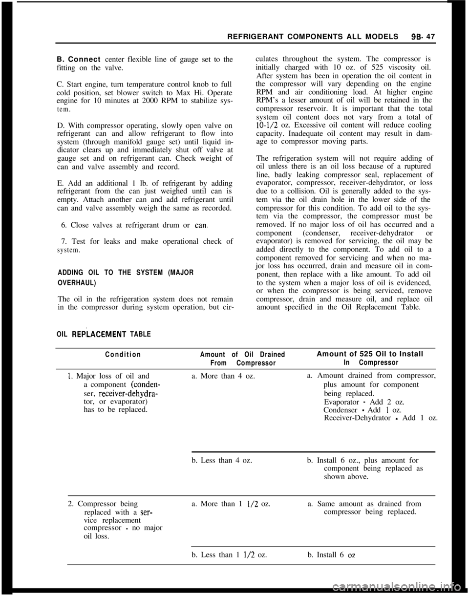
amount specified in the Oil Replacement Table.
OIL REP,‘LACEMENT TABLE
Condition
1. Major loss of oil and
a component (conden-
ser, receiver-dehydra-
tor, or evaporator)
has to be replaced.
Amount of Oil Drained
From Compressora. More than 4 oz.Amount of 525 Oil to Install
In Compressora. Amount drained from compressor,
plus amount for component
being replaced.
Evaporator
- Add 2 oz.
Condenser
- Add I oz.
Receiver-Dehydrator
- Add 1 oz.
b. Less than 4 oz.b. Install 6 oz., plus amount for
component being replaced as
shown above.
2. Compressor being
replaced with a
ser-vice replacement
compressor
- no major
oil loss.a. More than 1
l/2 oz.a. Same amount as drained from
compressor being replaced.
b. Less than 1
l/2 oz.b. Install 6 oz
Page 557 of 625
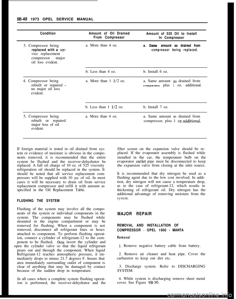
98-48 1973 OPEL SERVICE MANUALCondition3. Compressor being
replaced with a ser-vice replacement
compressor major
oil loss evident.
Amount of Oil Drained
From Compressora. More than 4 oz.Amount of 525 Oil to Install
In Compressor
a.
Same amount as drained from
compressor being replaced.4. Compressor being
rebuilt or repaired
-no major oil loss
evident.b. Less than 4 oz.
a. More than 1
l/2 oz.b. Install 6 oz.
a. Same amount a.s drained from
compressor, plus
1 oz. additional.
5. Compressor being
rebuilt or repaired
major loss of oil
evident.b. Less than 1
l/2 oz.
a. More than 4 oz.b. Install 7 oz.
a. Same amount as drained from
compressor, plus 1
ozadditional.If foreign material is noted in oil drained from sys-
tem or evidence of moisture is obvious in the compo-
nents removed, it is recommended that the entire
system be flushed and the receiver-dehydrator be
replaced. A full oil charge of 10 oz. of 525 viscosity
refrigeration oil should be replaced in the system. It
should be noted that all service replacement com-
pressors will be supplied with 10 pz. of oil. In most
cases it will be necessary to drain oil from service
replacement compressor and refill it with amount as
specified in the Oil Replacement Table.filter screen on the expansion valve should be re-
placed. If the evaporator assembly is flushed while
installed in the car, the temperature bulb on the
evaporator outlet pipe must be disconnected to keep
the expansion valve from closing at the inlet source.
FLUSHING THE SYSTEMIt is recommended that dry nitrogen be used as a
flushing agent due to the low cost involved. In addi-
tion, dry nitrogen will not cause a temperature drop,
as in the case of refrigerant-12, which results in
thickening of refrigerant oil. Dry nitrogen has the
additional advantage of removing moisture from thesystem.Flushing of the system may involve all the compo-
nents of the system or individual components in the
system. The components may be flushed while
mounted in the engine compartment or may be
removed for flushing. When a component is not
removed, disconnect all refrigerant lines or hoses
attached to component. To perform flushing operat-
ion, connect a cylinder of refrigerant-12 to the com-
ponent to be flushed, ,then invert the cylinder and
open the cylinder valve so that the liquid refrigerant
pours out and through the component. When liquid
Refrigerant-12 reaches atmospheric pressure, it im-
mediately drops to minus 21.7 degrees F. Insure that
area immediately surrounding outlet of component is
clear of anything that may be damaged by contact
because of the sudden drop in temperature.MAJOR REPAIR
REMOVAL AND INSTALLATION OF
COMPRESSOR
- OPEL 1900 - MANTA
Removal
I. Remove negative battery cable from battery.
2. Remove air cleaner and heat pipe. Cover the
carburetor to keep out dirt etc.
3. Discharge system. Refer to DISCHARGING
SYSTEM.
In all cases where a complete system flushing operat-4. While system is discharging remove sheet metal
ion is performed, the receiver-dehydrator and thecover. See Figure
9B-50.
Page 560 of 625
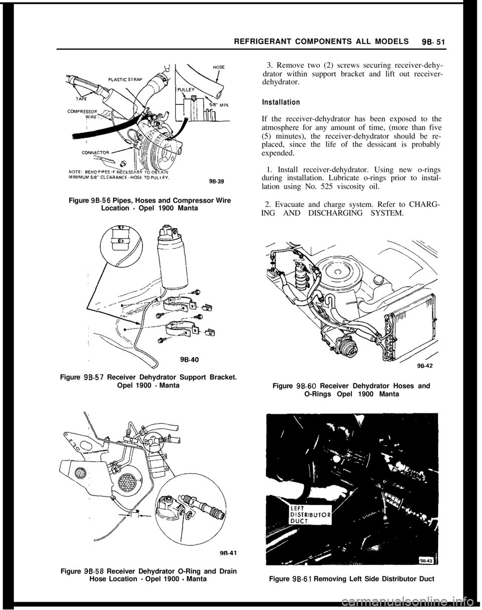
REFRIGERANT COMPONENTS ALL MODELSSB- 51
3. Remove two (2) screws securing receiver-dehy-
drator within support bracket and lift out receiver-
dehydrator.
InstallationIf the receiver-dehydrator has been exposed to the
atmosphere for any amount of time, (more than five
(5) minutes), the receiver-dehydrator should be re-
placed, since the life of the dessicant is probably
expended.
1. Install receiver-dehydrator. Using new o-rings
during installation. Lubricate o-rings prior to instal-
lation using No. 525 viscosity oil.
Figure 98.56 Pipes, Hoses and Compressor Wire
Location
- Opel 1900 Manta2. Evacuate and charge system. Refer to CHARG-
ING AND DISCHARGING SYSTEM.
Figure 98.57 Receiver Dehydrator Support Bracket.
Opel 1900
- Manta
Figure 98-59 Receiver Dehydrator O-Ring and Drain
Hose Location
- Opel 1900 - MantaFigure 9B-60 Receiver Dehydrator Hoses and
O-Rings Opel 1900 Manta
Figure 9B-61 Removing Left Side Distributor Duct
Page 563 of 625

96-54 1973 OPEL SERVICE MANUAL
valve. The filter screen at the inlet port may be re-
placed. Remove screen by threading a lo-32 NF
screw into old filter screen. With a washer and a nut
on the screw arranged to work as a puller screw, hold
the body of the screw and turn the nut. Insert the
new filter screen into the inlet port and lightly tap
screen only enough to seat.
1. Install expansion valve using new o-rings during
installation. Lubricate o-rings prior to installation
using No. 525 viscosity oil.
2. Install evaporator assembly and case attaching
screws. See Figure 9B-70.3. Install blower motor assembly into case and se-
cure with attaching screws. See Figure
9B-69.4. Install finger guard shields and fan housing case.
See Figure
9B-69.5. Install resistor assembly and electrical connector.
Install blower motor connector. See Figure
9B-69.6. Install assembly into car carefully guiding
evaporator pipes up through cowl opening. See Fig-
ure
9B-71.Figure 93-7 1 Inlet and Outlet Pipes and O-Rings
-Opel 1900 Manta
7. Install two (2) upper attaching evaporator at-
taching nuts. See Figures 9B-66 and
9B-67.8. Install two (2) attaching case mounting bracket
to instrument panel screws. See Figure
9B-67.9. Connect two (2) drain hoses underneath evapora-
tor.10. Install evaporator inlet and outlet pipes retainer
and rubber grommet. See Figure
9B-65.11. Connect vacuum cut-off switch and electrical
wiring, making sure the delay restrictor and checkvalve hoses are installed correctly. See Figures
9B-63and 64.
.gB-72 Delay Restrictor and Check Valve Hose.Assembly
12. Install refrigerant hoses and pipes using new
o-rings on line fittings and evacuate system. Refer to
EVACUATING SYSTEM.
13. While system is being evacuated, install in-line
fuse and left side of distributor duct. See Figure 9B-
61.14. Install glove box.
15. Install negative battery cable and charge system.
Refer to CHARGING SYSTEM.
REMOVAL AND INSTALLATION OF CONDENSER
ASSEMBLY -OPEL 1900. MANTA
Removal
1. Remove negative battery cable from battery.
2. Remove air cleaner.
3. Discharge system. Refer to DISCHARGING
SYSTEM.
4. While system is discharging, remove lower radia-
tor hose from radiator and drain coolant into a suita-
ble container.
5. Remove fan shroud.
6. On vehicles with automatic transmission, un-
screw oil lines from connectors on lower radiator
tank and plug lines. It is essential that no dirt enters
the oil lines. When unscrewing oil lines, hold connec-
tors on lower radiator tank with pliers to avoid leak-
ages. Ensure that no dirt enters oil cooler.
7. Remove upper radiator hose from radiator.
8. Remove lower attaching nut and slide radiator
upward and out of engine compartment.
9. Remove inlet and outlet hoses from condenser
Page 564 of 625

REFRIGERANT COMPONENTS ALL MODELS99.55pipes and tape closed the open ends of refrigerant
lines, and also the open ends of the inlet and outlet
pipes of the condenser.
10. Remove two (2) top retaining screws.
Figure
9,S-73 Condenser Retaining Screws - Opel
1900
- Manta
11. Remove radiator grille and two (2) condenser to
body mounting screws. See Figure 98.74.
Figure 98-74 Condenser Assembly and Attachments.
Opel 1900
- Manta
12. Remove condenser.
Installation
If refrigerarit circuit or condenser has been exposed
to the atmosphere and moisture may be present in
the circuit, the system and/or component must beFigure 98-75 Condenser Assembly Mounting Brackets
Opel 1900 Manta
flushed prior to installation. Refer to FLUSHING
THE SYSTEM.
1. Install comjenser into car and install 2 condenser
to body mounting screws. See Figure 98-74. Install
radiator grill.
2. Install 2 top retaining screws.
3. Remove tape from the condenser pipes and re-
frigerant hoses and install hoses using new o-rings on
lines lubricated with No.
525 viscosity oil.
4. Evacuate system. Refer to EVACUATING SYS-
TEM.
5. While system is being evacuated, install radiator
into engine compartment and secure lower attaching
nut.
Figure 98.76 Clearance Between Lower Radiator
Tank and Fan Blades
- Opel 1900 Manta
6. On vehicles with automatic transmissions, fasten
Page 567 of 625

98-58 1973 OPEL SERVICE MANUAL
2. Discharge system. Refer to DISCHARGING
SYSTEM.
3. While system is discharging remove air cleaner
and loosen idler pulley and bracket assembly. See
Figure 98-80.
4. Remove bolt holding compressor adapter fitting
into rear head. Disengage from compressor and tape
closed openings in both lines and ports in rear head.
It is important to seal compressor ports to avoid a
loss of refrigeration oil and also to prevent foreign
material and moisture from entering compressor. See
Figure 9B-82.
5. Remove bolt and ground wire, unplug electrical
connector, and remove 2 rear compressor mounting
bolts. See Figure 98-82.
6. Remove 2 front compressor mounting bolts,
clutch drive belt, and lift out compressor. During
removal, maintain the compressor position so that
the sump is downward. Do not’rotate compressor
shaft. See Figure 9B-84.
Installation1. Install compressor into mounting brackets and
secure with 4 mounting bolts. See Figure
9B-84.2. Untape lines and ports, and install compressor
adapter fitting and bolt using new o-rings. See Figure
9B-82.3. Evacuate system. Refer to, EVACUATING
SYSTEM.
4. While system is being evacuated, install drive belt
and tighten idler pulley. See Figure
9B-80.5. Install bolt and ground wire and plug in electrical
connector. See Figure
9B-83.6. Install air cleaner and negative battery cable.
7. Charge system. Refer to, CHARGING SYS-
TEM.
REMOVAL AND INSTALLATION OF
RECEIVER.DEHYDRATOR
ASSEMBLY. GT
Removal1. Discharge system. Refer to DISCHARGING
SYSTEM.
2. Disconnect refrigerant lines to both ends of re-
ceiver-dehydrator and tape closed open ends of
re-
9862Figure 98.85 Refrigeration Hose Clamps Installation
GT
frigerant lines, and also the open
e:nds of the inlet and
outlet pipes of the receiver-dehydrator. See Figure
9B-86.Figure 98.86 Receiver-Dehydrator GT
3. Remove 2 screws securing receiver-dehydrator
and clamps to support bracket and lift out receiver
dehydrator. See Figure
9B-86.
Installation1. Install receiver-dehydrator using new o-rings
during installation. Lubricate o-rings prior to instal-
lation using No. 525 viscosity oil.
.
Page 570 of 625

REFRIGERANT COMPONENTS ALL MODELS96.61
CAPILLARY T”BEFigure 98.95 Evaporator and Expansion Valve
Assembly GT
valve from refrigerant lines, and tape closed open
ends of lines and inlet and outlet ports of expansion
valve.
Installation5. Install resistor assembly.
6. Install evaporator assembly into car and install
mounting bracket. See Figure
9B-96.Figure 98.96 Evaporator and Blower Assembly
- GT
If expansion valve or refrigerant lines have been ex-
posed to
,the atmosphere for any amount of time and
moisture may have entered the valve or the system,
flush the system and install new receiver-dehydrator
or valve as necessary.7. Untape the refrigerant lines and the inlet and
outlet pipes from the evaporator and install using
new o-rings on line fittings.
Due to the possible adjustment difficulties involved
if the expansion valve is disassembled, disaisembly of
the valve is not recommended. The valve may be
cleaned by submerging it in a bath of trichlorethy-
lene, alcohol, or similar solvent. Dry by blowing iil-tered compressed air through the outlet port of the
valve. The filter screen at the inlet port may be re-
placed. Remove screen by threading a lo-32 NF
screw intp old filter screen. With a washer and a nut
on the screw arranged to work as a puller screw, hold
the body of the screw and turn the nut. Insert the
new filter screen into the inlet port and lightly tap
screen only enough to seat.
1. Install expansion valve using new o-rings during
installation. Lubricate o-rings prior to installation
using No. 525 viscosity oil.
2. Install evaporator assembly and case attaching
screws.
3. Install blower motor assembly into case and se-
cure with attaching screws.
4. Install finger guard shields and fan housing case.Figure 98-97 Refrigerant Hoses and Hose Clamps
Under Car
- GT
Page 572 of 625

REFRIGERANT COMPONENTS ALL MODELSSB-632. Install condenser into car and secure with 4 at-
taching screws. See Figure
9B-101.3. Untape discharge line and pipe and install using
new o-rings lubricated with No. 525 viscosity oil.
Figure
99.102 Condenser - Receiver - Dehydrator
O-Rings. GT
4. Untape and install inlet and outlet pipes into the
receiver-dehydrator using new o-rings lubricated
with No. 525 viscosity oil.
Figure
98-103 Condenser Assembly - GT
5. Evacuate system. Refer to EVACUATING SYS-
TEM.
6. While system is being evacuated, install the char-
coal cannistor, washer jar, battery tray and battery
and connect negative battery cable.
7. Charge system. Refer to CHARGING SYS-
TEM.
DISASSEMBLY AND REASSEMBLY OF CLUTCH
DRIVE PLATE AND SHAFT SEALIt is not necessary to remove the compressor or dis-connect refrigerant lines to remove or install clutch
parts on the GT, however, the compressor must be
removed from the Opel 1900
- Manta.
Disassembly
1. Firmly clamp holding fixture (J-9396) in a vise
and attach compressor assembly to fixture (see Figwe
9B-104).
-_ .s -Figure SE-104 Removing or Installing Shaft Nut
2. Hold hub of clutch drive plate with wrench
(J-9403). Using special thin wall 9/16 inch socket
(J-9399) and 3/g inch drive, remove shaft nut.
3. Install threaded hub puller (J-9401) onto hub of
clutch drive plate (see Figure
9B-105). Hold body of
hub puller with wrench, tighten center screw of hub
puller, and lift off clutch drive plate and woodruff
key.Figure SE-105 Removing Clutch Drive Plate