headlamp OPEL GT-R 1973 Service Manual
[x] Cancel search | Manufacturer: OPEL, Model Year: 1973, Model line: GT-R, Model: OPEL GT-R 1973Pages: 625, PDF Size: 17.22 MB
Page 19 of 625

CC-10 1973 OPEL SERVICE MANUAL
wiper blades. Check amount and direction of fluid
sprayed by washers during use.,
E. Defrosters - Check performance by moving con-
trols to “DEF” and noting
am$nmt of air directed
against the windshield.
I
F. Wheel Alignment and
Balabce - In addition to
abnormal tire wear, the need fbr wheel alignment
service may be indicated by a pull to the right or
!eftwhen driving on a straight and level road. The need
for wheel balancing is usually
iddicated by a vibra-
tion of the steering wheel or
se;+ tihile driving at
normal highway speeds.I
IG. Brakes
- Be alert to illumiriation of the brake
warning light or changes in braking action,
SUCK as
repeated pulling to one side, unusual sounds when
braking or increased brake pedal travel. Any of thesecould indicate the need for
brakk system inspection
and/or service.
H. Parking Brake and Transmission “PARK”
Mechanism
- Check parking brake holding ability by
parking on a fairly steep hill and restraining the vehi-
cle with the parking brake only.
eon cars with auto-
matic transmissions, check the holding ability of the
“PARK” mechanism by releasing all brakes after
the transmission selector lever hak been placed in the“P” position.
I. Glass
- Check for broken, scrritched, dirty or da-
maged glass on vehicle that
coulld obscure vision’or
become an injury hazard.
J. Lights and Buzzers
- Check all instrument panel
illuminating and warning lights,’ seat belt reminder
light and buzzer, ignition key
b&er, interior lights,
license plate lights, side marker! lights, headlamps,
parking lamps, tail lamps, brake lights, turn signals,
backup lamps, and hazard warding flashers. Have
someone observe operation of
&ach exterior light
while you activate the controls: The operation of
instrument panel warning lights is covered in the
“Starting and Operating“ section of your
Own&%
Manual.K. Transmission Shift Indicator
‘- Check to be sure
automatic transmission shift
indiCator accurately i”-
dicates the shift position selected.
I
CAUTION: Before making thk check below,I
be sure to have a clear dist&e ahead and:
behind the car, set the parking brake and
firmly apply the foot brake.
Do not depress
accelerator pedal. Be prepared to
turn off ’
ignition switch
immediat+y if engine
should start.L. Starter Safety Switch (Automatic Transmissibn
Cars)
- Check starter safety switch by placing the
transmission in each of the driving gears while
at-tempting to start the engine. The starter should oper-ate only in the Park (“P”) or Neutral (“N”)
positions.
M. Horn
- Blow the horn occasionally to be sure thatit works. (Ignition switch must be in the “ON” posi-
tion.)
N. Seat Back Latches
- Check to see that seat back
latches are holding by pulling forward on the top of
each folding seat back.
0. Rearview Mirrors and Sun Visors
- Check that
friction joints are properly adjusted so mirrors and
sun visors stay in the selected position.
P. Door Latches
- Check for positive closing, latch-
ing and locking.
Q. Hood Latches - Check to make sure hood closesfirmly by pressing on the hood at the latching point
after each closing. Check also for broken, damaged
or missing parts which might prevent secure latch-
ing.R. Fluid Leaks
- Check for fuel, water, oil or other
fluid leaks by observing the ground beneath the vehi-cle after it has been parked for a while. If gasoline
fumes or fluid are noticed at any time, the cause
should be determined and corrected without delay
because of the possibility of fire.
S. Exhaust System
- Be alert to any change in the
sound of the exhaust system or a smell of fumes
which may indicate a leak.
Head Restraints
- Check that no head restraint
components are missing, damaged or loose. (Does
not apply to GT Models).
Disc BrakesCheck brake pads and condition of rotors while
wheels are removed during tire rotation. (Note belowregarding more frequent checks also applies to disc
brakes.)
Parking and Drum BrakesCheck drum
brake linings and other internal brake
components at each wheel (drums, wheel cylinders,
etc.). Parking brake adjustment also should be
checked whenever drum brake linings are checked.
NOTE: More frequent checks should be
made if driving conditions a.nd habits result
in frequent brake application. When brakes
require relining, it is recommended thatyou use those genuine General Motors
parts specified for your car,and Delco fluid
as required.
Page 66 of 625

LIGHTING SYSTEMSlF-45LIGHTING SYSTEMS
CONTENTS
Subject
DESCRIPTION AND OPERATION:
LightingSystems................................................................
DIAGNOSIS:MAINTENANCT AND ADJUSTMENTS:
Headlamp Aiming..............................................................
MAJOR REPAIR:
Opel 1900
- Manta
HeadlightSwitch............................................................
Fog Lamp or Heated Rear Window Switch
..........
SealBeam........................................................................
Tail Lamps........................................................................
LicensePlateLamp........................................................
FrontSideMarker..........................................................
Rear Side Marker..........................................................
Courtesy Light................................................................
DoorJamSwitch............................................................
GT
Front Turn Signal..........................................................
SealBeam........................................................................
Tail Lamps........................................................................
Side Marker......................................................................
LicensePlateLamp........................................................
Backup Lamp
..................................................................
InteriorLight....................................................................
Headlamp Switch..........................................................
DoorJamSwitch............................................................
SPECIFICATIONS:
Page No.
1 F-45
1 F-46
1 F-46
1 F-47
1 F-47
1 F-40
1 F-49
1 F-49
1 F-50
1 F-50
1 F-50lF-51lF-51lF-51
1 F-52
1 F-52
1 F-53
1 F-53
1 F-53
1 F-53
DESCRIPTION AND OPERATION
DESCRIPTION OF LIGHTING SYSTEMThe
three-baition light switch on Opel 1900 and
Manta corjtrols the headlights, taillights, parking
lights, side marker lights, instrument panel lights,
and the lic&se plate light.
When the
Qght switch knob is pulled out to the first
stop, the .pxking lights, side marker lights, the Ii-
cerise plate light, and the instrument panel lights will
light.
Pulling the knob out all the way turns the headlights
on.The instrument panel lights come on when the head-
light switch is pulled out to the first stop or pulled
out ‘all the way. The instrument panel lights are
turned off by turning the switch knob counterclock-
wise past the first detent.
Page 67 of 625

1F. 46 1973 OPEL SERVICE MANUAL
’
/
Headlight High-Low Beam Control and Passing:
SignalI
When the headlights have been switched on, high
and low beam selection is made by raising the direc-
tional signal lever toward steering wheel. Each
ti&the lever is raised, beam position, will change.
When the headlights are not on, a flashing headlight
signal may be given by raising and lotiering the di-
rectional signal lever. With the headlights on and
inlow beam position, raising and lowering the direc-
tional signal lever will also cause the headlights to
flash.
Fog Light SwitchAll Rallye models are equipped with two white f?g
lights mounted below the front bumper.
The fog light toggle switch is located on the
insty-ment cluster to the left of the temperature and
fuelgauge cluster.
/
The fog lights can be turned off at any time by the
toggle switch, but can only be tyrned on when: :
1. The ignition switch on or the
?gine running.!
2. The fog light toggle switch lower half is pushed
in.3. The parking lights and/or low beam headlights
are
OKThe fog lights are automatically turned off if the
ignition switch is on and the headlights are switched
to high beam position.
Courtesy LightThe courtesy light illuminates the interior of the Car
when any door is opened. The courtesy light can also
be turned on with all doors closed by tilting the l&s.
GT Headlamp MechanismThe concealed headlamps are moved mechanically.
Pushing actuating lever on left side of console opens
headlamps and pulling lever closes headlamps. Two
(2) meshing gear segments convert the movement, of
the lever to a rotation of 180 degrees. The pivots of
the headlamps lie below the centerline so that with
headlamps in closed position, the headlamp housing
is flush with front sheet metal. Refer to Group 110,
Section “F”, for service procedures on the GT head-
lamp mechanism.
A white indicator lamp in the instrument panel lights
if the headlamps are not completely opened lorclosed The switches of the headlamp electrical sys-
tem are located behind the left headlamp operating,
mechanism.
MAINTENANCE AND ADJUSTMENTSHEADLAMP AIMING
The headlamps must be properly aimed in order to
obtain maximum road illumination and safety that
has been built into the headlighting equipment. With
the Guide T-3 type sealed beam units, proper aiming
is even more important because the increased range
and power of this lamp make even slight variations
from recommended aiming hazardous to approach-
ing motorists. The headlamps must be checked for
proper aim whenever a sealed beam unit is replaced
and after an adjustment or repairs of the front end
sheet metal assembly.
Regardless of method used for checking headlamp
aim, car must be at normal weight, that is, with gas,
oil, water, and spare tire. Tires must be uniformly
inflated to specified pressure. If car will regularly
carry an unusual load in rear compartment, or a
trailer, these loads should be on car when headlamps
are checked. Some States have special requirements
for headlamp aiming adjustment, and these require-
ments should be known and observed.
Horizontal and vertical aiming of each seal beam
unit is provided by two adjusting screws which move
the mounting ring in the body against the tension of
the coil spring. There is no adjustment for focus,
since the sealed beam unit is set for proper focus
during manufacturing assembly.
MAJOR REPAIRHEADLIGHT SWITCH
- OPEL 1900. MANTA
Removal1. Remove instrument cluster cover panel. See Sec-
tion H.
2. Compress retaining springs and pull switch out.
See Figure 1 F-
1.3. Pull multiple socket off switch.
Installation
1: Plug multiple socket in switch and push switch in
panel until clips lock in place.
2. Replace instrument cover and secure with two (2)
screws.
Page 68 of 625

LIGHTING SYSTEMSlF-472. Install switch in panel.
3. Replace instrument cluster cover.
EXTERIOR LIGHTSModels 51-53-54
Headlamp Sealed Beam Unit Removal1. Remove two screws on headlight ring.
2. Remove four screws holding headlight retainer to
body. See Figure lF-3.
Figure 1 F-l Removing Headlight Switch
I
3.
Rep& two (2) plugs over screws and replace
heater control knobs.
FOG LIGHT OR HEATED REAR GLASS SWITCHRemoval I
1. Removd instrument cluster cover. See Section H.
I
2. Press
ddwn retaining clip and pull switch out. See
Figure lF-2.
Figure 1 F-3 - Removing Headlight Retainer
- Models
51-53-54
3. Disconnect wiring connectors,
4. Remove headlight from inside engine compart-
ment.
Figure 1Fi2 - Removal of Fog Light or Heated Rear
Glass Switch
3. Removelwires from switch.
Installation/
1. Connect;wire to switch,
Installation1. Plug in wiring connector on sealed beam and re-
place four (4) headlight retaining screws.
2. Replace headlight ring.
Models 57-57R
Removal
I. Disconnect wiring connector.
2. Remove four screws holding headlight retainer
from inside engine compartment.
Page 72 of 625

I
2. Install Switch to door jam.
I
EXTERlOd LIGHTS. GTLIGHTING SYSTEMSlF- 51
Removing~Parking-Light Housing1.
Remove lamp lens.
2. Remove lamp housing.
3.
Discon$ect electrical wires. See Figure lF-13.
lnstallatioh
1.
Con& electrical wires.2. Install famp housing and lens.
Removal df Front Directional Signal Lamp1.
Remove lamp lens.
2.
Removk lamp housing.
3.
DisconAect electrical wires. See Figure lF-14.Figure
lb14 Removal Front Directional Lamp Lens
Installation1.
Con&t electrical wires.
2. Install lamp housing and lens.
Removal {f Headlamp Sealed Beam1. Rotate fieadlamp to open position.
2.
Remove headlamp shield. See Figure lF-15.3.
Removk headlamp attaching screws and take off
headlamp.; See Figure
lF-16.4. Disconiect electrical wires.
/Installatiot
1. Install headlamp with three (3) attaching screws.
IFigure lF-15 Removing Headlamp Shield
Figure 1 F-16 Removing Headlight Attaching Screws
2. Connect electrical wires.
3. Replace headlamp shield.
Before installation of headlamp shield, adjust head-
lamp for proper aim.
Removal of Rear Directional Signal Lamp. Stop and
Tail Lamp1. Remove lamp lens.
Page 74 of 625

I
LIGHTING SYSTEMSlF- 53
/Removal if Back-Up Lamp1. Remode back-up lens.
2.
Remo+ lamp housing.
3. Discodnect electrical wires. See FigurelF-20
Removal of Headlamp Switch1. Completely remove left headlamp and headlamp
housing.
2. Remove switch from base plate. See Figure lF-21.
Fibure lF-20 Removal of Back-Up Light
Interior djght RemovalI
1. Disco@ect battery.
2. Remohe lens.
3.
RemoF base plate by removing two (2) screws.
4. Unplulg wires.
I
I
InstallationI
1. Connect wires to proper plugs.
2. Install! base plate.
3. Install! lens.
4. Con&t battery.
I
,Figure
1 F-2 1 Light Switch Positions
Installation1. Install switch to base plate.
2. Install left headlamp and housing.
Door Jam Switch Removal1. Remove door jam switch attaching screws.
2. Remove switch and disconnect wire.
Installation1. Connect wire to switch.
2. Replace switch on door jam with attaching screw.
Page 75 of 625

lG- 54 1973 OPEL SERVICE’ MANtiAL/SIGNAL SYSTEMSCdNTENTS
9Subject
DESCRIPTION AND OPERAT!ON:
Directional Signal Lever
. . . . . . . . . . . . . . . . . . . . . . . . . . . . . . . . . . . . . . . . . . . . . . . . . .
Horn. . . . . . . . . . . . . . . . . . . . . . . . . . . . . . . . . . . . . . . . . . . . . . . . . . . . . . . . . . . . . . . . . . . . . . . . . . . . . . . . . . . . . . . .HazardWarning
Flasher. . . . . . . . . . . . . . . . . . . . . . . . . . . . . . . . . . . . . . . . . . . . . . . .BrakeSystemWarningLight
. . . . . . . . . . . . . . . . . . . . . . . . . . . . . . . . . . . . . . . .DIAGNOSIS:
SignalSystem,.......................
i . . . . . . . . . . . . . . . . . . . . . . . . . . . . . . . . . . . . . . . . . . . . .MAINTENANCE AND ADJUS,TMENTS:
MAJOR REPAIR:
Directional Signal Switch
:. . . . . . . . . . . . . . . . . . . . . . . . . . . . . . . . . . . . . . . . . . . . .
HornRemoval. . . . . . . . . . . . . . . . . . . . . . . . . . . . . . . . . . . . . . . . . . . . . . . . . . . . . . . . . . . . . . . . . . . . . .Removing Horn Contact
. . . . :.............................................
SPECIFICATIONS:
FuseChart. . . . . . I . . . . . . . . . . . . . . . . . . . . . . . . . . . . . . . . . . . . . . . . . . . . . . . . . . . . . . . . . . . . . . . . . . . . .Page No.
1 G-54
1 G-54
1 G-55
lG-55 _1 G-55
1 G-55
16-551 G-55
1 G-56
DESCRIPTION AND OPERATION
DIRECTIONAL SIGNAL LEVERThe direction signal switch lever is a multi- purpose
lever controlling direction signals, passing signal,
and high and low beams. See Figure
lG-1.301Gl
Figure lG-1 Directional Signal Position for Headlamp
OperationThe direction signal lever is provided with a
two-step mechanism for operation of headlight high and
low beams, and passing signal (not in New Jersey).
With headlights off, moving the lever repeatedly to-
wards steering wheel flashes headlights as a passing
signal. With headlights on, moving the lever repeat-
edly towards steering wheel up to first stop also
flashes passing signal regardless whether or not the
direcl:ion signals are switched on. When the lever is
moved up to the second stop, the headlights are
changed from high to low beam
dr vice versa. On all
Rallye cars, when switching from low to high beam
position, with the fog lamp instrument panel switch
“ON” and ignition switch in “RUN” position, the
fog lights are automatically
switChed off. Direction
signals work in the normal manner; pushing the lever
up for right turn signal and pulling the lever down
for left turn signal.
The horn button is located in the center part of the
steering wheel. The horn is actuated by pushing
down on the ends of both spokes on Opel 1900 andManta’s or on the center horn button on the Rallye.
The button is provided with a spring-loaded plunger.See Figure
lG-2.
Page 79 of 625

1 H- 581973 OPEL SERVICE MANUAL
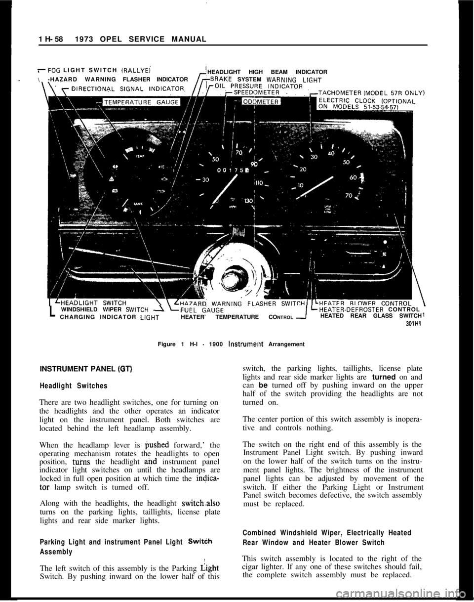
/-FOG LIGHT SWITCH IRALLYEi
\HEADLIGHT HIGH BEAM INDICATOR
-HAZARD WARNINGFLASHERINDICATORSYSTEM WARN,NGLlGHT
LWINDSHIELD WIPER SWlTCH -1 LFUEL&,UGELHEATER-DEFROSTER CONTROL
CHARGING INDICATOR LlGHTHEATER’ TEMPERATURE CONTROLHEATED REAR GLASS SWITCH1
301H1Figure 1 H-l
- 1900 lnstrumellt Arrangement
INSTRUMENT PANEL
(GT)I
Headlight SwitchesThere are two headlight switches, one for turning on
the headlights and the other operates an indicator
light on the instrument panel. Both switches are
located behind the left headlamp assembly.
When the headlamp lever is @shed forward,’ the
operating mechanism rotates the headlights to open
position, tuins the headlight and instrument panel
indicator light switches on until the headlamps are
locked in full open position at which time the indica-
tar lamp switch is turned off.
Along with the headlights, the headlight switch,also
turns on the parking lights, taillights, license plate
lights and rear side marker lights.
Parking Light and instrument Panel Light SwitCh
AssemblyThe left switch of this assembly is the Parking Light
Switch. By pushing inward on the lower half of thisswitch, the parking lights, taillights, license plate
lights and rear side marker lights are turned on and
can be turned off by pushing inward on the upper
half of the switch providing the headlights are not
turned on.
The center portion of this switch assembly is inopera-
tive and controls nothing.
The switch on the right end of this assembly is the
Instrument Panel Light switch. By pushing inward
on the lower half of the switch turns on the instru-
ment panel lights. The brightness of the instrument
panel lights can be adjusted by movement of the
switch. If either the Parking Light or Instrument
Panel switch becomes defective, the switch assembly
must be replaced.
Combined Windshield Wiper, Electrically Heated
Rear Window and Heater Blower SwitchThis switch assembly is located to the right of the
cigar lighter. If any one of these switches should fail,
the complete switch assembly must be replaced.
Page 93 of 625

1 J- 72 1973 OPEL SERVICE MANUAL
I
WIRING IDIAGRAMS
CONTENTS
Subject
1973 WIRING DIAGRAMS: Windshield Wiper and
Horn:- Opel 1900 -
Manta....................................I.............. ..............................
Windshield Wiper and Horn’- Rallye ..........................
Windshield Wiper
andHorn!-GT
..................................
Turn Signal and Hazard Flasher
-
Opel 1900 - Manta !
........................................................
Turn Signal and Hazard Flasher
- GT ..........................
Oil, Fuel,
Temp.: Tach, Stop and Brake
Warning Light
.GT........................................................
Blower Motor, Lighter and
Rackup Lights -
Qpel 1900.Manta ........................................................
Blower Motor and Lighter
.,GT....................................
Indicator Lights and Gauges
- Opel 1900 -
Manta ........................................................................\
........
Indicator Lights
andGauges.Rallye ..........................
Dome Light and Buzzer
- Opel 1900 - Manta..........
Dome Light, Buzzer and Clock - GT ............................
Headlamps
- Opel 1900 ’
....................................................
Headlamps
.Mantaj............................................................
Headlamps and Fog Lights
.Rallye ..............................
Headlamps, Parking, Tail and Instrument
PanelLighting.GT ........................................................
Left Parking and Tail Lights
- Opel 1900 -
Manta ..................................i.............................................
Right Parking and Tail Lights
- Opel 1900 -
Manta................. ..*............................................................
Starting, Ignition and Charging
-
Opel 1900.Manta..........i.............................................
Starting, Ignition and Charging
- GT ..........................
Instrument
Panel.GT ......................................................
A/C Generatorand Regulator
- All Models..............
Seat Belt Warning System (Manual Transmission)
-Opel1909-Manta ..........................
Seat Belt Warning System (Automatic Transmission)
.Opel 1900 - Manta..........................
Seat Belt Warning System (Manual Transmission)
- GT........................................................ Page No.
1 J-74
1 J-75
1 J-76
1 J-77
1 J-78
1 J-79
1 J-80
lJ-81
1 J-82
1 J-83
1 J-84
1 J-85
1 J-86
1 J-87
1 J-88
1 J-89
1 J-90
1 J-91
1 J-92
1 J-93
1 J-94
1 J-95
1 J-96
1 J-97
1 J-98
Page 107 of 625

1 J- 86 1973 OPEL SERVICE MANUALi
Figure 1 J-l 3; Headlamps - Opel 1900