radiator cap OPEL GT-R 1973 Service Manual
[x] Cancel search | Manufacturer: OPEL, Model Year: 1973, Model line: GT-R, Model: OPEL GT-R 1973Pages: 625, PDF Size: 17.22 MB
Page 17 of 625
IoC-91973 OPEL SERVICE MANUAL
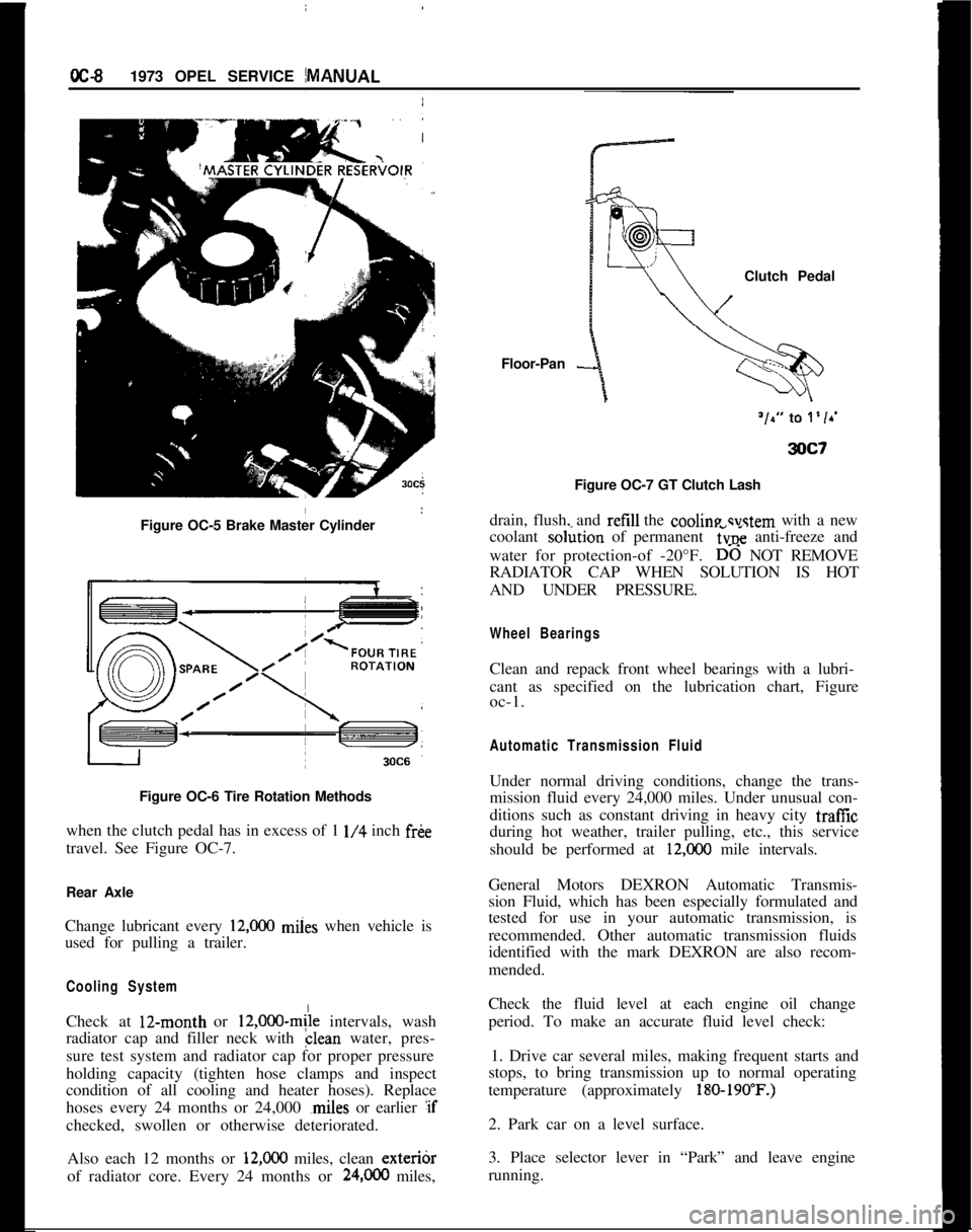
Figure OC-5 Brake Master Cylinder
I
Figure OC-6 Tire Rotation Methods
when the clutch pedal has in excess of 1
l/4 inch fr&
travel. See Figure OC-7.
Rear Axle
Change lubricant every
12,ooO miies when vehicle is
used for pulling a trailer.
Cooling SystemCheck at 12-month or
12,000~mile intervals, wash
radiator cap and filler neck with clean water, pres-
sure test system and radiator cap for proper pressure
holding capacity (tighten hose clamps and inspect
condition of all cooling and heater hoses). Replace
hoses every 24 months or 24,000 ,miles or earlier :if
checked, swollen or otherwise deteriorated.
Also each 12 months or
12,ooO miles, clean exteribr
of radiator core. Every 24 months or
24,OCO miles,Floor-Pan
-Clutch Pedal
Figure OC-7 GT Clutch Lash
drain, flush, and refill the cooline svstem with a new
coolant so&ion of permanent
6~; anti-freeze and
water for protection-of -20°F.
D-6 NOT REMOVE
RADIATOR CAP WHEN SOLUTION IS HOT
AND UNDER PRESSURE.
Wheel BearingsClean and repack front wheel bearings with a lubri-
cant as specified on the lubrication chart, Figure
oc-1.
Automatic Transmission FluidUnder normal driving conditions, change the trans-
mission fluid every 24,000 miles. Under unusual con-
ditions such as constant driving in heavy city traffic
during hot weather, trailer pulling, etc., this service
should be performed at
12,COO mile intervals.
General Motors DEXRON Automatic Transmis-
sion Fluid, which has been especially formulated and
tested for use in your automatic transmission, is
recommended. Other automatic transmission fluids
identified with the mark DEXRON are also recom-
mended.
Check the fluid level at each engine oil change
period. To make an accurate fluid level check:
1. Drive car several miles, making frequent starts and
stops, to bring transmission up to normal operating
temperature (approximately
180-190’F.)2. Park car on a level surface.
3. Place selector lever in “Park” and leave engine
running.
Page 314 of 625
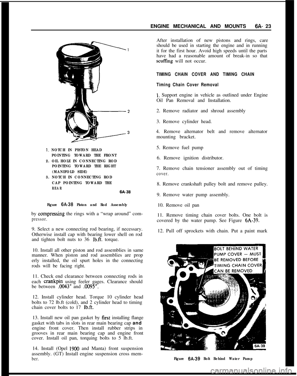
ENGINE MECHANICAL AND MOUNTS6A- 231. NOTCH IN PISTON HEAD
POINTING TOWARD THE FRONT
2. OIL HOLE IN CONNECTING ROD
POINTING TOWARD THE RIGHT
(MANIFOLD SIDE)
3. NOTCH IN CONNECTING ROD
CAP POINTING TOWARD THE
REAR6A-36
Figure
6A-39 Piston and Rod Assemblyby oompressing the rings with a “wrap around” com-
pressor.9. Select a new connecting rod bearing, if necessary.
Otherwise install cap with bearing lower shell on rod
and tighten bolt nuts to 36
lb.ft. torque.
10. Install all other piston and rod assemblies in same
manner. When piston and rod assemblies are prop
erly installed, the oil spurt holes in the connecting
rods will be facing right.
11. Check end clearance between connecting rods in
each crankpin using feeler gages. Clearance should
be between
.0043” and .0095”.
12. Install cylinder head. Torque 10 cylinder head
bolts to 72 lb.ft (cold), and 2 cylinder head to timing
chain cover bolts to 17
lb.ft.13. Install new oil pan gasket by first installing flange
gasket with tabs in slots in rear main bearing cap and
engine front cover. Then install rubber strips in
grooves in rear main bearing cap and engine front
cover. Install oil pan, torquing bolts to 5 lb.ft.
14. Install (Opel
1900 and Manta) front suspension
assembly. (GT) Install engine suspension cross mem-
ber.After installation of new pistons and rings, care
should be used in starting the engine and in running
it for the first hour. Avoid high speeds until the parts
have had a reasonable amount of break-in so that
scuffling will not occur.
TIMING CHAIN COVER AND TIMING CHAIN
Timing Chain Cover Removal
1, Support engine in vehicle as outlined under Engine
Oil Pan Removal and Installation.
2. Remove radiator and shroud assembly
3. Remove cylinder head.
4. Remove alternator belt and remove alternator
mounting bracket.
5. Remove fuel pump
6. Remove ignition distributor.
7. Remove chain tensioner assembly out of timing
cover.8. Remove crankshaft pulley bolt and remove pulley.
9. Remove water pump assembly.
10. Remove oil pan
11. Remove timing chain cover bolts. One bolt is
covered by the water pump. See Figure 6A-39.
12. Pull off sprockets with chain. Put a paint mark
Figure 6A-39 Bolt Behind Water Pump
Page 323 of 625
66.321973 OPEL SERVICE MANUAL
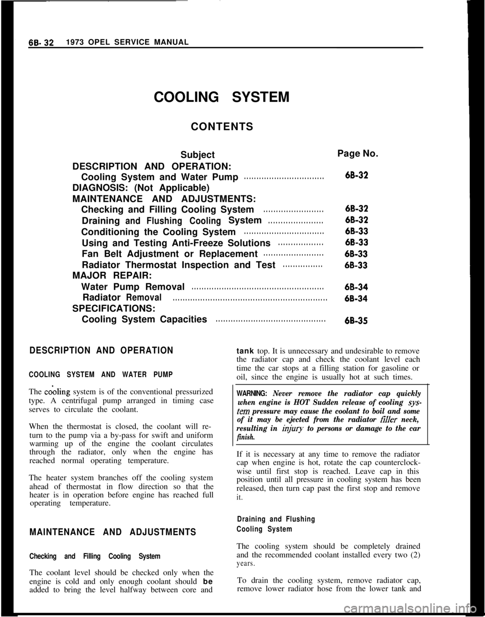
COOLING SYSTEM
CONTENTS
Subject
DESCRIPTION AND OPERATION:
Cooling System and Water Pump
. . . . . . . . . . . . . . . . . . . . . . . . . . . . . . . .DIAGNOSIS: (Not Applicable)
MAINTENANCE AND ADJUSTMENTS:
Checking and Filling Cooling System
. . . . . . . . . . . . . . . . . . . . . . . .Draining
andFlushingCoolingSystem. . . . . . . . . . . . . . . . . . . . . .Conditioning the Cooling System
. . . . . . . . . . . . . . . . . . . . . . . . . . . . . . . .Using and Testing Anti-Freeze Solutions
. . . . . . . . . . . . . . . . . .Fan Belt Adjustment or Replacement
. . . . . . . . . . . . . . . . . . . . . . . .Radiator Thermostat Inspection and Test
. . . . . . . . . . . . . . . .MAJOR REPAIR:
Water Pump Removal
. . . . . . . . . . . . . . . . . . . . . . . . . . . . . . . . . . . . . . . . . . . . . . . . . . . . .Radiator
Removal. . . . . . . . . . . . . . . . . . . . . . . . . . . . . . . . . . . . . . . . . . . . . . . . . . . . . . . . . . . . . .SPECIFICATIONS:
Cooling System Capacities
. . . . . . . . . . . . . . . . . . . . . . . . . . . . . . . . . . . . . . . . . . . .Page No.
68-32
6B-32
68-32
68-33
68-33
68-33
68-33
68-34
68-34
6B-35
DESCRIPTION AND OPERATION
COOLING SYSTEM AND WATER PUMPThe coiling system is of the conventional pressurized
type. A centrifugal pump arranged in timing case
serves to circulate the coolant.
When the thermostat is closed, the coolant will re-
turn to the pump via a by-pass for swift and uniform
warming up of the engine the coolant circulates
through the radiator, only when the engine has
reached normal operating temperature.
The heater system branches off the cooling system
ahead of thermostat in flow direction so that the
heater is in operation before engine has reached full
operating temperature.
MAINTENANCE AND ADJUSTMENTS
Checking and Filling Cooling SystemThe coolant level should be checked only when the
engine is cold and only enough coolant should be
added to bring the level halfway between core andtank top. It is unnecessary and undesirable to remove
the radiator cap and check the coolant level each
time the car stops at a filling station for gasoline or
oil, since the engine is usually hot at such times.
WARNING: Never remove the radiator cap quickly
when engine is HOT Sudden release of cooling
sys-
tern pressure may cause the coolant to boil and some
of it may be ejected from the radiator
filler neck,
resulting in
inl’ury to persons or damage to the car
finish.If it is necessary at any time to remove the radiator
cap when engine is hot, rotate the cap counterclock-
wise until first stop is reached. Leave cap in this
position until all pressure in cooling system has been
released, then turn cap past the first stop and remove
it.
Draining and Flushing
Cooling SystemThe cooling system should be completely drained
and the recommended coolant installed every two (2)
years.To drain the cooling system, remove radiator cap,
remove lower radiator hose from the lower tank and
Page 325 of 625
6B- 341973 OPEL SERVICE MANUAL
test by partially draining the cooling system and dis-
connecting the water outlet housing from the ther-
mostat housing which is mounted on the right front
side of cylinder head.
The standard thermostat valve should start to open
at 189 degrees F and fully open at approximately 212
degrees F. If thermostat does not operate at specified
temperatures, it should be replaced as it cannot be
repaired.MAJOR REPAIR
WATER PUMP REPAIRSThe water pump bearing outer race is shrunk fit into
the water pump cover. For this reason the cover,
shaft bearing, and hub are not repairable.
Water Pump RemovalOpel radiators do not have a drain plug. Drain radia-
tor by first, loosening radiator cap, then remove
lower hose from lower radiator tank.
1. Drain coolant into a clean container. Remove
radiator and shroud.
2. Remove fan belt.
3. Remove fan blade and pulley on water pump shaft.
4. Disconnect inlet hose and heater hose from water
pump. Remove bolts, pump assembly and gasket
from timing chain cover.
5. Check pump shaft bearing for end play or rough-
ness in operation. If bearings are not in serviceable
condition, the assembly must be replaced.
Water Pump Installation1. Make sure the gasket surfaces on pump and timing
chain covers are clean. Install pump assembly with
new gasket. Bolts must be tightened uniformly.
Torque to 11 lb. ft.
2. Install radiator and shroud. Connect radiator hose
to pump inlet and heater hose to nipple.
3. Install fan pulley and fan blade, tighten attaching
bolts securely. Install belts and adjust for proper
tension.4. Fill cooling system and check
,for leaks at pump
and hose joints.
RADIATOR REMOVAL AND INSTALLATION
RemovalI. Loosen radiator cap, then remove lower radiator
hose and drain radiator coolant into suitable con-
tainer.
2. On vehicles with automatic transmission, unscrew
oil lines from connectors on lower radiator tank and
plug lines. On GT models with automatic transmis-
sion the lines have to be disconnected at the coupling
before removing from the tank. It is essential that no
dirt enters the oil lines. When unscrewing oil lines,
hold connectors on lower radiator tank with pliers to
avoid leakages. Ensure that no dirt enters oil cooler.
3. Remove lower attaching nut and slide radiator
upward and out of engine compartment.
Installation1. Install radiat,or into engine compartment and se-
cure lower attaching nut.
2. On vehicles with automatic transmissions, fasten
oil cooler lines to lower radiator tank. It is essential
that no dirt enters the oil lines. When tightening oil
lines, hold connectors on lower radiator tank with
pliers to avoid leakages. Ensure that no dirt enters oil
cooler. Torque to 1 I-15
lbs.ft.3. Install lower radiator hose and add collected coo-
lant.
All Opels are provided with a radiator initial fill of
an antifreeze solution containing corrosion inhibitor.
The antifreeze has either a glycol or glycerin base
and protects the engine against freezing, down to
minus 22 degrees F. (minus 30 degrees C.). Before
the start of the cold season, coolant must be checked
with a hydrometer and if necessary, brought to the
necessary specific gravity by adding anti-freeze with
a glycol or glycerin base. As the specific gravities of
all anti- freeze solutions having a glycol or glycerin
base are practically the same, the hydrometer can be
used for all these types. Because of the tolerances of
the hydrometer, or slight differences in specific
gravity, variations of plus or minus 5 degrees can be
expected. Coolant must be checked at a temperature
of plus 68 degrees F. (plus 20 degrees C.)
Page 505 of 625

8A.41973 OPEL SERVICE MANUAL
Figure SA-5 Location of Fender Attaching Bolts
9. Fit new fender and apply a sealing compound, as
required, to joint. See Figure
SA-6.Figure 8A-6 Sealing Location
10. Coat fender inside with a dampening compound.
REMOVAL AND INSTALLATION OF HEADLAMP
COVERING (OPEL
1900. MANTA)
Removal1. Remove radiator grille.2. In engine compartment unscrew headlamp cover-
ing.
Se:e Figure SA-7.Figure 8A-7 Headlamp Covering Attaching Bolts
Installation1. Install headlamp covering. See Figure
SA-7.2. Install radiator grille.
REMOVAL AND INSTALLATION OF HEADLAMP
ASSEMBLY
(GT)1. Move headlamp to open position and remove
headlamp cover. See Figure
SA-8.Figure EA.8 Removing Headlamp Cap
Page 508 of 625

HOOD, FENDERS, AND GRILLE8A- 72. Remove two plastic caps and phillips screws from
outer end of grille extension.
3. Remove grille extension,
Installation1. Install grille extension and secure with Phillips
screws and two (2) plastic caps.
2. Install hex head screw and washer holding grille
extension to baffle plate.
REMOVAL AND INSTALLATION OF RADIATOR
GRILLE
(OPEL 1900. MANTA)
A. Removal (Model 57)1. Remove the
five (5) radiator grille attaching
screws. See Figure
8A-15.Figure 8A-15 Radiator Grille Attaching Screws
2. Remove radiator grille towards the top so that the
lower guide pins do not break off. See Figure 8A- 16.Figure 8A-16 Removing Radiator Grille
Installation (Model 57)
1. Install radiator grille, aligning guide pins into
lower panel. See Figure
8A-16.2. Secure grille with five (5) attaching screws. See
Figure 8A-2.
Removal (Models 51.53, and 54)
1. Remove the three (3) radiator grille attaching
screws. See Figure
8A-17.Figure 8A.17 Location of Radiator Grille AttachingSCWWS
2. Remove radiator grille towards the top SO that the
lower guide pins do not break off.
Page 513 of 625

9A-4 1973 OPEL SERVICE MANUAL
Figure 9A-4 Heater Control
Blower Switch - This switch actuates blower motor
to low or high blower speed.
HEATER SYSTEM OPERATION
To operate heater proceed as follows:
1. Position air inlet, heater-defroster control as
desired.
White arrow head pointing down--air out of heater
outlets. White arrow head pointing up--air out of
defroster outlets.
Between lower and upper position--air to both heater
and defroster outlets.
2. Position temperature control as desired to increase
or decrease temperature of air flow.
3. Position blower switch as desired to operate
blower at low or high speed.
Dlid3NDSlS
HEATER SYSTEM TROUBLE DIAGNOSIS
TROUBLE
Temperature of heated air at outlets too low.
CAUSE AND CORRECTION
Check radiator cap for proper sealing action-- re-
place if necessary.
Check for adequate coolant supply. If level is down,
correct cause of coolant loss and refill radiator.
Inspect hose for kinks--relieve kink or replace hoses.
Check thermostat operation by measuring tempera-
ture of coolant at radiator. Temperature should be
within 5 degrees F. of thermostat rated value (189
degrees F.).
Check that air doors and water temperature control
valye are operating properly.
Check for plugged heater core--backflush heater core
as necessary.
TROUBLE
Inadequate defrosting action.
CAUSE AND COiiRECTlON
Examine heater-defroster door for proper operat-
ions--adjust bowden cable as required so that door is
fully closed in FULL DEFROST position.
Check that air hoses connecting to defroster outlets
are secure.
Check for air leaks around edges of heater air dis-
tributor housing--seal leaks as necessary with body
sealer. Check for body air leaks and seal as necessary
with body sealer.
TROUBLE
Blower inoperative.
CAUSE AND CORRECTION
Check blower fuse--replace if necessary, fuse position
3 - amperage 8.
Check wiring for open circuit--correct as required. Inspect for defective component (i.e., blower switch
or blower motor)--replace or repair as necessary.
MAINTENANCE AND ADJUSTMENTS
CONTROL CABLE ADJUSTMENT
Adjustment of control cables is accomplished by po-
sitioning of the jacket or sheath of the control cable
as held by the clamps on the control assembly and
heater case.
To adjust control cables, loosen clamps and move
cable sheath in or out as required to obtain full travel
of lever or of door or both.
Page 518 of 625

HEATER SYSTEM. GT9A- 9
REMOVAL AND INSTALLATION HEATER VALVE
Removal
1. Remove lower radiator hose and drain and collect
coolant.
2. Disconnect control cable.
3. Loosen heater hose clamps and remove valve from
hoses. See Figure 9A-17.SPECIFICATIONS
EngineRecommended Coolant
.__,.__...._...__.,.,...,......Thermostat Opens At (Degrees) F.
..__..___...Installation
1. Install valve into heater hoses and install hose
clamps.
2. Connect control cable.
3. Install lower radiator hose and add collected coo-
lant.
.....................................Ethylene-Glycol Base
...................................................................189Cooling
SystemCapacity(WithHeater)..........................................................................6Qt.BlowerMotorType
......................................................................................................12VDC
BlowerFanType
..................................................................................................SquirrelCage
Page 520 of 625

HEATER SYSTEM. OPEL 1900. MANTA9A- 11air is attained, as the water does not cool down in the
second part of the core.
A Water Outlet
B Water Inlet
The center lever actuates the two-stage blower mo-
tor.Lever positions:
Left to Center
- Motor Switched Off
Right of Center
- Lo Blower
Right
- Hi Blower
The lower lever opens and closes the air door which
channels the air flow to either the lower heater out-
lets or to the defroster outlets.
In the left lever position, the air inlet is closed. Up
to the center position, the air is directed
t,o the lower
heater outlets.
When moving the lever from center position towards
the right, the air flow to the lower
heatezr outlets is
reduced and increased to the defroster
csutlets.With the lever in its right position, the air is directed
to the defroster outlets only. For windshield defrost-
ing, all levers have to be moved to the right.
FUNCTION OF THE HEATER AND VENTILATION
SYSTEMThe engine hood is provided with slots in front of the
windshield. The air is directed through the slots into
the heater housing located in the engine compart-
ment, flows into the air distributor housing, and
from there to the lower heater outlets and,/or defros-
ter outlets, depending on the position of the control.
The two-stage blower motor is arranged in the heater
housing above the heater core and actuated by the
center control. The blower motor draws in the air
entering through the slots, blows the air through the
heater core into the air distributor housin:?, and from
there to the lower heater outlets and/or defroster
outlets, depending on the position of the lower con-
trol. See Figure 9A-32.
The heater valve regulates the flow of coolant
through the heater core, thereby varying
t:he temper-
ature of the air flow past the core.
The ventilation of vehicle interior is completed by a
draft-free air circulation pattern. Vent
slots are ar-
ranged below the back window which
are: connected
through channels to the rear quarter
iside panel.
From here, the inside air escapes into
the! open. TheFigure
9A-32 Air Flow
head wind (caused by the car traveling down the
road) promotes this process so that there is always
fresh air in vehicle interior.
On the Model 54 Station Wagon, there will be no air
outlets in the rear. For adequate flow-through type
ventilation, it will be necessary to open a rear win-
dow.Aside from the fresh air admission through the
heater system, two fresh air inlet nozzles are ar-
ranged in the center of the instrument panel. These
nozzles can be turned to direct the air flow in the
desired direction. In addition, rotary flaps allow the
regulation of the entering air or to shut off the air
completely.
These nozzles admit unheated fresh air only and
operate independent of the heater and defroster sys-
tem.
DIAGNOSIS
HEATER SYSTEM TROUBLE DIAGNOSIS
TROUBLETemperature of heated air at outlets too low.
CAUSE AND CORRECTIONCheck radiator cap for proper sealing action. Re-
place, if necessary.
Check for adequate coolant supply. If level is down,
correct cause of coolant loss and refill radiator.
Inspect hose for kinks. Relieve kink or replace hoses.
Check thermostat operation by measuring tempera-
ture of coolant at radiator. Temperature should be
within 5 degrees F. of thermostat rated value (189
degrees F.).
Page 546 of 625
REFRIGERANT COMPONENTS ALL MODELS
99.37
in front of the radiator so that it receives a high
volume of air flow. Air passing over the condenser
absorbs the heat from the high pressure gas and
causes the refrigerant to condense into a high pres-
sure liquid.Receiver. DehydratorThe receiver-dehydrator is located in the engine
compartment. The purpose of the receiver dehydra-
tor is two fold: the unit insures a solid column of
liquid refrigerant to the expansion valve at all times,
and also absorbs any moisture in the system that
might be present. A bag of desiccant (moisture ab-
sorbing material) is provided to absorb moisture. A
sight glass (see Figure 9B-33) permits visual check-
ing of the refrigerant flow for bubbles or foam. The
continuous appearance of bubbles or foam above an
ambient temperature of 70 degrees F. usually indi-
cates an inadequate refrigerant charge. Bubbles or
foam appearing at ambient temperatures below 70
degrees F. do not necessarily indicate an inadequate
charge and may appear even when the system is
operating properly. A filter screen in the unit pre-
vents foreign material from entering the remainder
of the system.
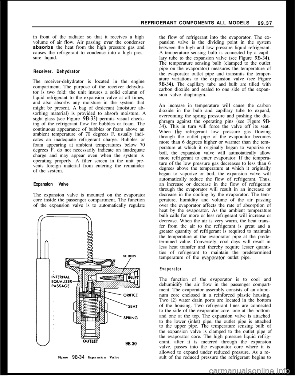
Expansion ValveThe expansion valve is mounted on the evaporator
core inside the passenger compartment. The function
of the expansion valve is to automatically regulate
SCREEN
lLCl98.30
Figure 98-34 Expansion Valvethe flow of refrigerant into the evaporator. The ex-
pansion valve is the dividing point in the system
between the high and low pressure liquid refrigerant.
A temperature sensing bulb is connected by a capil-
lary tube to the expansion valve (see Figure
9B-34).The temperature sensing bulb (clamped to the outlet
pipe on the evaporator) measures the temperature of
the evaporator outlet pipe and transmits the temper-
ature variations to the expansion valve (see Figure
9B-34). The capillary tube and bulb are tilled with
carbon dioxide and sealed to one side of the expan-
sion valve diaphragm.
An increase in temperature will cause the carbon
dioxide in the bulb and capillary tube to expand,
overcoming the spring pressure and pushing the dia-
phragm against the operating pins (see Figure 9B-
34). This in turn will force the valve off its seat.
When the refrigerant low pressure gas flowing
through the outlet pipe of the evaporator becomes
more than 6 degrees higher or warmer than the tem-
perature at which it originally began to vaporize or
boil, the expansion valve will autmotatically allow
more refrigerant to enter evaporator. If the tempera-
ture of the low pressure gas decreases to less than 6
degrees above the temperature at which it originally
began to vaporize or boil, the expansion valve will
automatically reduce the flow of refrigerant. Thus,
an increase or decrease in the flow of refrigerant
through the evaporator will result in an increase or
decrease in the cooling by the evaporator. The tem-
perature, humidity and volume of the air passing
over the evaporator affects the rate of absorption of
heat by the evaporator. As the ambient temperature
bulb calls for more or less refrigerant will increase or
decrease. When the air is very warm, the heat trans-
fer from the air to the refrigerant is great and a
greater quantity of refrigerant is required to maintain
the temperature at the evaporator pipe at the prede-
termined value. Conversely, cool days will result in
less heat transfer and thereby require lesser quanti-
ties of refrigerant to maintain the predetermined
temperature of the evaporator outlet pipe.
EvaporatorThe function of the evaporator is to cool and
dehumidify the air flow in the passenger compart-
ment. The evaporator assembly consists of an alumi-
num core enclosed in a reinforced plastic housing.
Two (2) water drain ports are located in the bottom
of the housing. Two refrigerant lines are connected
to the side of the evaporator core: one at the bottom
and one at the top. The expansion valve is attached
to the lower (inlet) pipe, the outlet pipe is attached
to the upper pipe. The temperature sensing bulb of
the expansion valve is clamped to the outlet pipe of
the evaporator core. The high pressure liquid refrig-
erant, after it is metered through the expansion
valve, passes into the evaporator core where it is
allowed to expand under reduced pressure. As a re-
sult of the reduced pressure the refrigerant begins to