roof rack OPEL GT-R 1973 Service Manual
[x] Cancel search | Manufacturer: OPEL, Model Year: 1973, Model line: GT-R, Model: OPEL GT-R 1973Pages: 625, PDF Size: 17.22 MB
Page 71 of 625

1 F- 50 1973 OPEL SERVlCE,MANUAL
Installation
1. Connect wiring harness.
2. Replace housing with two (2) screws.
3. Rep&e lens.
Rear RemovalRemove two screws from support bracket aed
remove housing and lens. See Figure lF-10.
,&y...2&L&-i -:,..; 3O’F’OFigure 1 F-10
- Removing Rear Side Marker Lampx
kallationInstall housing and lens with two (2) attach&gSCFSVS.
INTERIOR LIGHTS
Courtesy Light Removal1. Pry courtesy light out of roof frame, as shown in
Figure 1 F-
11.
t2. Pull wires off flat plugs. See Figure lF-12.
Figure lF-12 -Courtesy Light Wire Connections
Installation1. Connect wires to flat plugs, a) red wire, b)
greywire, and c) brown wire.
2. Push light back into roof frame.
Door Jam Switch Removal1. Remove door jam switch
attach’ing screws.
2. Remove switch and disconnect wire.
Installation1. Connect wire to switch.
Figure lF-1 1
- Removing Courtesy LightFigure 1 F-l 3 Removing Parking Light Lens
Page 147 of 625

2F-241973 OPEL SERVICE MANUAL
ROOF AND SUN ROOF
CONTENTS
,.,Subject
DESC,RIF?TION AND OPERATION: (Not Applicable)
DIAGNOSIS: Sun Roof Diagnosis
. . . . . . . . . . . . . . . . . . . . . . . . . . . . . . . . . . . . \
. . . . . . . . . . . . . . . . . . . . . .
MAINTENANCE AND ADJUSTMENTS:Sun Roof Height Adjustment
. . . . . . . . . . . . . . . . . . . . . . . . . . . . . . . . . . . . \
. . . .
MAJOR REPAIR:
Removal and Installation
Sun Roof Panel andFrame. . . . . . . . . . . . . . . . . . . . . . . . . . . . . . . . . . . . \
. . . .
Velvet Strip and Weather Strip. . . . . . . . . . . . . . . . . . . . . . . . . . . . . . . .
RearGuides andCables. . . . . . . . . . . . . . . . . . . . . . . . . . . . . . . . . . . . \
. . . . . . . . . .
Drive Pinion. . . . . . . . . . . . . . . . . . . . . . . . . . . . . . . . . . . . \
. . . . . . . . . . . . . . . . . . . . . . . . . . . . . . . . . .
Water DrainHoses. . . . . . . . . . . . . . . . . . . . . . . . . . . . . . . . . . . . \
. . . . . . . . . . . . . . . . . . . .
Luggage Rack. . . . . . . . . . . . . . . . . . . . . . . . . . . . . . . . . . . . \
. . . . . . . . . . . . . . . . . . . . . . . . . . . . . .
SPECIFICATIONS: (Not Applicable) Page No.
2F-24
2F-26
iF-27
2F-29
2F-29
2F-30
2F-31
2F-3i
DIAGNOSIS
SUN ROOF DIAGNOSIS
_ -
CONhTlONPAUSEI~C~RRECTI~X~
Sun roof does not operate
Transporter cable lengths
parallel. equal.Close sun roof, slide sun roof
frame to rear, remove.crank
handle
and cable crank. Check
that sun roof bears against sun
roof opening velvet strip and
that lifter’ portion of rear lifter
guides is positioned approximately
90 degrees to guide rails.
Turn
cable crank fully clockwise and
reinstall into cable box.
Transporter cables damaged
or worn. Replace cables. Both cables
must be replaced if either one
is damaged or worn.
Page 148 of 625

ROOF AND SUN ROOFZF-25ConditionCallseCorrectionSun roof lifts up on one
side only.Lifter wedge welded to under-
Remove sun roof panel and bend
side of sun roof panel doeslifter wedge so that it squarely hits
not run up ramp welded inramp. The only adjustment for
center of sun roof track.the ramp is the angle of the
rear portion. This should be
adjusted so that the wedge smoothly
rides up the ramp.
Transporter cable or drive
pinion damaged.If the transporter cable is worn
or damaged, replace both
cables. If drive pinion worn or
damaged, replace drive pinion and
also both transporter cables.
Sun roof scrapes on car roof
when closing sun roof.Lifters do not lie flat.Close sun roof, slide sun roof
frame to the rear and open and close
sun roof slightly noting operation
of lifters. Rework if necessary,plastjc lifter cushion with tile
to permit lifter to lie flat.
Sparingly lubricate lifter guide.
Sun roof frame becomes
detached.Attaching clips have lost
elasticity.Install new clips
Water enters car interior.
Water drain hoses blocked.
Bent water drain hoses
Rear water drain hoses have
been pulled out of rubber
grommets.
Velvet strips on front and
rear of sun roof do not seal
properly.Clean hoses with compressed air
or a flexible steel cable.
NOTE: To clear rear water
drain hoses, the sun roof panel
and frame must be removed.
Blowing out of rear drain hoses
from trunk compartment hose end
is not recommended due to
possibility of soiling car
interior.
Attempt to straighten drain
hoses by working a suitable
tube or cable through hose.
Replace hose if above corrective
action is not satisfactory.
Apply a small amount of rubber
cement to rear water drain
hoses and reinsert into rubber
grommet located in luggage
compartment floor panel.
Check sun roof for correct
height adjustment. If height
adjustment is correct, but a
tight seal does not exist,
relocate velvet strip upward
for better seal, or replace
velvet strip.
Page 151 of 625

2F-281973 OPEL SERVICE MANUAL
guides to height adjustment rings, loosen second
screw (see Figure 2F-6), and swing guides away from
guide rail.
NOTE: When swinging front guides inboard, be
careful not to change position of height adjustment
rings. It is suggested that the position of the height
adjustment rings be marked with a pencil prior to
loosening of front guide attaching screws.
5. Retighten remaining screw holding front guide in
position to prevent height adjustment rings from
turning.
6. Turn lifter guide tension springs 90 degrees in-
board and pull lifters out of sun roof panel brackets
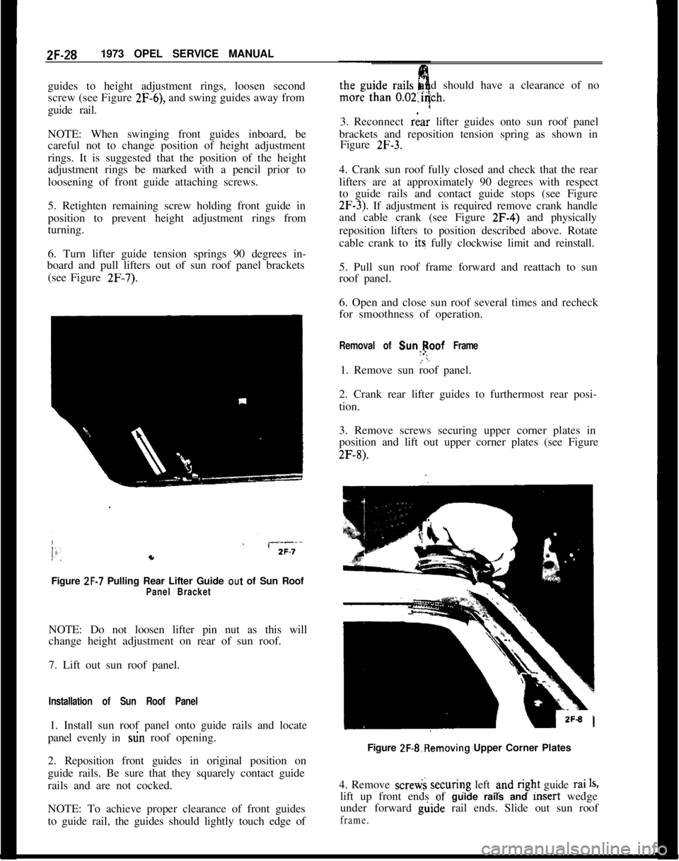
(see Figure
2F-7).Figure
ZF-7 Pulling Rear Lifter Guide out of Sun RoofPanel BracketNOTE: Do not loosen lifter pin nut as this will
change height adjustment on rear of sun roof.
7. Lift out sun roof panel.
Installation of Sun Roof Panel1. Install sun roof panel onto guide rails and locate
panel evenly in stin roof opening.
2. Reposition front guides in original position on
guide rails. Be sure that they squarely contact guide
rails and are not cocked.
NOTE: To achieve proper clearance of front guides
to guide rail, the guides should lightly touch edge ofdshould have a clearance of no
3. Reconnect
riar lifter guides onto sun roof panel
brackets and reposition tension spring as shown in
Figure
2F-3.4. Crank sun roof fully closed and check that the rear
lifters are at approximately 90 degrees with respect
to guide rails and contact guide stops (see Figure
2F-3). If adjustment is required remove crank handle
and cable crank (see Figure 2F-4) and physically
reposition lifters to position described above. Rotate
cable crank to its fully clockwise limit and reinstall.
5. Pull sun roof frame forward and reattach to sun
roof panel.
6. Open and close sun roof several times and recheck
for smoothness of operation.
Removal of Sunlpoof Frame1. Remove sun roof panel.
2. Crank rear lifter guides to furthermost rear posi-
tion.
3. Remove screws securing upper corner plates in
position and lift out upper corner plates (see Figure
2F-8).Figure 2F-&Removing Upper Corner Plates
4. Remove scretii securing left und
r@t guide rai1%lift up front ends
of- guide rails and msert wedge
under forward g&de rail ends. Slide out sun roof
frame.
Page 153 of 625

2F-301973 OPEL SERVICE MANUAL
3. Unscrew and remove upper and lower corner
plates (see Figure 2F-8).4. Unscrew and remove left and right upper cable
shields ans pull cable ends out of cable box.
5. Pull cable and rear lifter guides out of leftand
right guide rails.
Installation of Rear Guides and Cable1. Check both cables for wear or damage. If eigher
cable is defective, replace both cables.
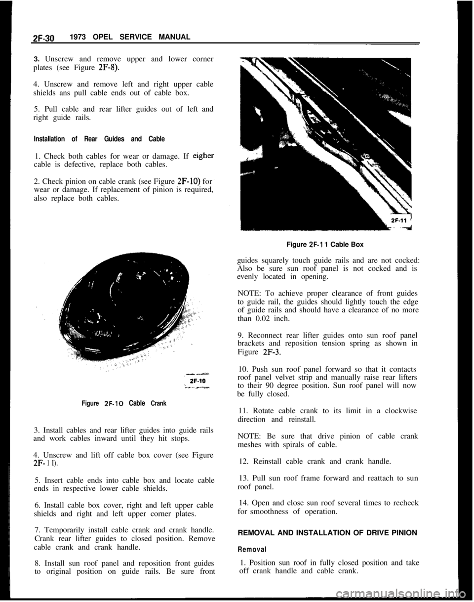
2. Check pinion on cable crank (see Figure
2F-IO) for
wear or damage. If replacement of pinion is required,
also replace both cables.
Figure ZF-10 Cable Crank3. Install cables and rear lifter guides into guide rails
and work cables inward until they hit stops.
4. Unscrew and lift off cable box cover (see Figure
2F- 1 I).5. Insert cable ends into cable box and locate cable
ends in respective lower cable shields.
6. Install cable box cover, right and left upper cable
shields and right and left upper corner plates.
7. Temporarily install cable crank and crank handle.
Crank rear lifter guides to closed position. Remove
cable crank and crank handle.
8. Install sun roof panel and reposition frontguides
to original position on guide rails. Be sure frontFigure
ZF-1 1 Cable Box
guides squarely touch guide rails and are not cocked:
Also be sure sun roof panel is not cocked and is
evenly located in opening.
NOTE: To achieve proper clearance of front guides
to guide rail, the guides should lightly touch the edge
of guide rails and should have a clearance of no more
than 0.02 inch.
9. Reconnect rear lifter guides onto sun roof panel
brackets and reposition tension spring as shown in
Figure
2F-3.10. Push sun roof panel forward so that it contacts
roof panel velvet strip and manually raise rear lifters
to their 90 degree position. Sun roof panel will now
be fully closed.
11. Rotate cable crank to its limit in a clockwise
direction and reinstall.
NOTE: Be sure that drive pinion of cable crank
meshes with spirals of cable.
12. Reinstall cable crank and crank handle.
13. Pull sun roof frame forward and reattach to sun
roof panel.
14. Open and close sun roof several times to recheck
forsmoothness of operation.
REMOVAL AND INSTALLATION OF DRIVE PINION
Removal1. Position sun roof in fully closed position and take
off crank handle and cable crank.
Page 155 of 625

2F-321973 OPEL SERVICE MANUAL
3. Carefully detach a portion of headlining around
window corner post involved.
4. Detach water drain hose from sun roof hose iit-
ting.
5. Remove cowl side kickpads.
6. Pull out from upper end front water drain hose.
Installation of Front Water Drain Hose
1. Insert from above water drain hose (wider end
upward) into door hinge pillar.
NOTE: Do not mistake front and rear water hoses.
The front hose is thinner than the rear hose and is
wider at the end which connects to hose fitting on
sun roof. The rear hose is uniform over its entire
length.
2. Work water drain hose downward through lower
half of door hinge pillar and be sure hose terminates
behind door sill flange at bottom of frbnt fender.
3. Cement upper portion of water drain hose to sun
roof hose fitting.
4. Cement detached portions of headlining into place
by use of rubber cement or nitrile vinyl trim adhesive
(3M Vinyl Trim Adhesive, Permalastic Vinyl Trim
Adhesive or equivalent).
5. Complete installation reverse of removal proce-
dures.
Removal of Rear Water Drain Hose1. Remove rear seat and rear seat back.2. Pry out plastic fasteners securing cardboard parcel
shelf in position and remove shelf.
3. Remove rear quarter trim pad.
4. Detach headlining only as required from area
around rear window pillar.
5. Pull out rear water drain hose.
Installation of Rear Water Drain Hose1. Install rear water drain hose in original position.
Insert hose from above and work downward. Ce-
ment both ends of hose in place.
2. Secure water drain hose in place along wheel-
house.3. Complete installation reverse of removal proce-
dures.
REMOVAL AND INSTALLATION
OF LUGGAGE
RACKAll 1973 luggage racks will be dealer installed, and
are held to the roof at the 4 corners. Removal and
installation is accomplished by removing the attach-
ing screw at each corner. See Figure
2F-14.Figure ZF-14 Luggage Rack
Page 619 of 625

MAJOR REPAIRRADIO
- OPEL 1900 - MANTA9c- 111
REMOVING AND INSTALLING RADIO
Removal ~
1. Rem&e control knobs and ornamental cover
plate. See Figure 9C-
15.2. Unscrew two (2) hex. nuts behind and remove
ornamental cover plate.
3. Unscrew support bracket from back of radio hous-
ing and air distribution housing. See Figure
9C-16.~ Figure 9C-16 Support Bracket
4. Remove radio.
Installation1. Install in reverse sequence to removal.
2. Trim radio.
REMOVAL AND INSTALLATION OF ANTENNA
Removal’1. Pull antenna cable out of radio socket.
2. Pull iubber grommet and antenna cable out of
cowl
pa+. See Figure 9C-17.3. Unscrew antenna from fender.
lnstallatipn1. Install in reverse
sequehce to removal.Figure 9C-17 Antenna and Cable
- Under Fender
2. Seal antenna lead-in to antenna mast area withsilastic sealer or equivalent. See’ Figure
9C-18.SEAL
TH’IS ANTENNA
h LEAD-IN ‘TO ANTENNA
MAST AREA WITHSILASTIC SEALER
OR EQUIVALENT
01RADIO ANTENNASEALING PROCEDURE9c-13
Figure 9C-18 Sealing Antenna Lead-in
to AntennaMast
3. Clean antenna contacting area at fender under-
side to a bright surface.
4. After installation of antenna, protect fender
against corrosion by spraying with a rustproof
paint or similar product.
5. Trim radio.