tire type OPEL GT-R 1973 Service Manual
[x] Cancel search | Manufacturer: OPEL, Model Year: 1973, Model line: GT-R, Model: OPEL GT-R 1973Pages: 625, PDF Size: 17.22 MB
Page 16 of 625
LUBRICATION AND MAINTENANCE OC-7SERVICESLUBE AND GENERAL MAINTENANCE
Vehicle operation under conditions such as heavy
dust, continuous short trips, use of other than un-
leaded or low lead fuels or pulling trailers, is not
considered normal use and therefore more frequent
maintenance will be required. Such additional
maintenance requirements are included where appli-
cable.
Engine OilChange each 4 months or
3,COO miles, whichever
occurs first, or each 2 months or
3,ooO miles when
the vehicle is operated under the following condi-
tions: (a) driving in dusty conditions, (b) trailer pull-
ing, (c) extensive idling or (d) short-trip operation at
freezing temperatures (with engine not thoroughly
warmed-up).Engine oils have a definite effect on ease of starting,
oil economy, combustion chamber deposits and en-
gine wear. It is recommended that a” oil which,
according to the label on the can is; (1) intended for
service SE and (2) passes car makers’ tests be used.
Oils confotming to these types contain detergent ad-
ditives. -
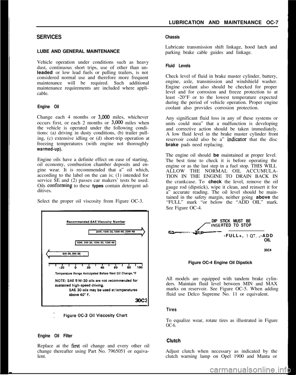
Select the proper oil viscosity from Figure OC-3.
Engine Oil FilterReplace at the first oil change and every other oil
change thereafter using Part No. 7965051 or equiva-
lent.
ChassisLubricate transmission shift linkage, hood latch and
parking brake cable guides and linkage.
Fluid LevelsCheck level of fluid in brake master cylinder, battery,
engine, axle, transmission and windshield washer.
Engine coolant also should be checked for proper
level and for corrosion and freeze protection to at
least -20°F or to the lowest temperature expected
during the period of vehicle operation. Proper engine
coolant also provides corrosion protection.
Any significant fluid loss in any of these systems or
units could mea” that a malfunction is developing
and corrective action should be taken immediately.
A low fluid level in the brake master cylinder front
reservoir could also be a” indtcator that the disc
brake pads need replacing.
The engine oil should be maintained at proper level.
The best time to check it is before operating the
engine or as the last step in a fuel stop. THIS WILL
ALLOW THE NORMAL OIL ACCUMULA-
TION IN THE ENGINE TO DRAIN BACK IN
the crankcase. To check the level, remove the oil
gauge rod (dipstick), wipe it clean, and reinsert it for
a” accurate reading. The oil level should be main-
tained in the safety margin, neither going above the
“FULL” mark “or below the “ADD OIL” mark.
See Figure OC-4.
DIP STICK MUST BE
INSERTED TO STOP
---L- -FULL+, 1 OT. ,-ADD
OIL
Figure OC-4 Engine Oil Dipstick
All models are equipped with tandem brake cylin-
ders. Maintain fluid level between MIN and MAX
marks on reservoir. See Figure OC-5. When adding
fluid use Delco Supreme No. 11 or equivalent.
TiresTo equalize wear, rotate tires as illustrated in Figure
OC-6.Adjust clutch when necessary as indicated by the
clutch warning lamp on Opel 1900 and Manta or
Page 67 of 625
1F. 46 1973 OPEL SERVICE MANUAL
’
/
Headlight High-Low Beam Control and Passing:
SignalI
When the headlights have been switched on, high
and low beam selection is made by raising the direc-
tional signal lever toward steering wheel. Each
ti&the lever is raised, beam position, will change.
When the headlights are not on, a flashing headlight
signal may be given by raising and lotiering the di-
rectional signal lever. With the headlights on and
inlow beam position, raising and lowering the direc-
tional signal lever will also cause the headlights to
flash.
Fog Light SwitchAll Rallye models are equipped with two white f?g
lights mounted below the front bumper.
The fog light toggle switch is located on the
insty-ment cluster to the left of the temperature and
fuelgauge cluster.
/
The fog lights can be turned off at any time by the
toggle switch, but can only be tyrned on when: :
1. The ignition switch on or the
?gine running.!
2. The fog light toggle switch lower half is pushed
in.3. The parking lights and/or low beam headlights
are
OKThe fog lights are automatically turned off if the
ignition switch is on and the headlights are switched
to high beam position.
Courtesy LightThe courtesy light illuminates the interior of the Car
when any door is opened. The courtesy light can also
be turned on with all doors closed by tilting the l&s.
GT Headlamp MechanismThe concealed headlamps are moved mechanically.
Pushing actuating lever on left side of console opens
headlamps and pulling lever closes headlamps. Two
(2) meshing gear segments convert the movement, of
the lever to a rotation of 180 degrees. The pivots of
the headlamps lie below the centerline so that with
headlamps in closed position, the headlamp housing
is flush with front sheet metal. Refer to Group 110,
Section “F”, for service procedures on the GT head-
lamp mechanism.
A white indicator lamp in the instrument panel lights
if the headlamps are not completely opened lorclosed The switches of the headlamp electrical sys-
tem are located behind the left headlamp operating,
mechanism.
MAINTENANCE AND ADJUSTMENTSHEADLAMP AIMING
The headlamps must be properly aimed in order to
obtain maximum road illumination and safety that
has been built into the headlighting equipment. With
the Guide T-3 type sealed beam units, proper aiming
is even more important because the increased range
and power of this lamp make even slight variations
from recommended aiming hazardous to approach-
ing motorists. The headlamps must be checked for
proper aim whenever a sealed beam unit is replaced
and after an adjustment or repairs of the front end
sheet metal assembly.
Regardless of method used for checking headlamp
aim, car must be at normal weight, that is, with gas,
oil, water, and spare tire. Tires must be uniformly
inflated to specified pressure. If car will regularly
carry an unusual load in rear compartment, or a
trailer, these loads should be on car when headlamps
are checked. Some States have special requirements
for headlamp aiming adjustment, and these require-
ments should be known and observed.
Horizontal and vertical aiming of each seal beam
unit is provided by two adjusting screws which move
the mounting ring in the body against the tension of
the coil spring. There is no adjustment for focus,
since the sealed beam unit is set for proper focus
during manufacturing assembly.
MAJOR REPAIRHEADLIGHT SWITCH
- OPEL 1900. MANTA
Removal1. Remove instrument cluster cover panel. See Sec-
tion H.
2. Compress retaining springs and pull switch out.
See Figure 1 F-
1.3. Pull multiple socket off switch.
Installation
1: Plug multiple socket in switch and push switch in
panel until clips lock in place.
2. Replace instrument cover and secure with two (2)
screws.
Page 189 of 625
3C-22 1973 OPEL SERVICE MANUAL.
FRONT END ALIGNMENT
CONTENTS
SubjectPage No.
DESCRIPTION AND OPERATION:
FrontWheelAlignment
. . . . . . . . . . . . . . . . . . . . . . ..“...........................DIAGNOSIS: (Not Applicable)
MAINTENANCE AND ADJUSTMENTS:
Inspection Before Checking Front Wheel Alignment
AdjustingCaster
. . . . . . . . ...’ . . . . . . . . . . . . . . . . . . . . . . . . . . . . . . . . . . . . . . . . . . . . . . . . . . . . .Adjusting Camber
. . . . . . . . . . . . . . . . . . . . . . . . . . * . . . . . . . . . . . . . . . . . . . . . . . . . . . . . . . . . . .Adjusting Toe-In
. . . . . . . . . . . . . . * . . . . . . . . . . . . . . . . . . . . . . . . . . . . . . . . . . . . . . . . . . . . . . . . .King Pin Inclination
. . . . . . . . . . . . . . . . . . . . . . . . . . . . . . . . . . . . . . . . . . . . . . . . . . . . . . . . . .MAJOR REPAIR: (Not Applicable)
SPECIFICATIONS:3C-223C-223C-233C-253C-253C-26
Wheel Alignment Specifications
. . . . . . . . . . . . . . . . . . . . . . . . . . . . . . . . . .3C-26
DESCRIPTION AND OPERATIONFRONT WHEEL ALIGNMENT
Wheel alignment is the mechanics of adjusting the
position of the front wheels in order to attain the
least steering effort with a minimal amount of tire
wear.handling, but require only reasonable accuracy to
provide normal tire life. With the type of front sus-
pension used, the toe-in adjustment is much more
important than caster and camber are as far as tire
wear is concerned.
Correct alignment of the chassis is essential to proper
alignment of front and rear wheels. Briefly, the es-
sentials are that the frame must be square in plain
view within specified limits, that the top and bottom
surfaces of the front cross member must be parallel
fore and aft, and that the upper and lower control
arm must be at correct location in respect to shafts
and the front cross member. All bushings, ball joints
and bolts must be of proper torque and in usable
condition.Caster and camber adjustments need not be consid-
ered unless visual inspection shows these settings to
be out, or unless the car gives poor handling on the
road. In the majority of cases, services consisting of
inflating tires to specified pressure and interchanging
tires at recommended intervals, balancing all wheels
and tires, adjusting steering gear and setting toe-in
correctly will provide more improvement in car han-
dling and tire wear than will other front end align-
ment adjustments.
Wheel and tire balance has an important effect on
steering and tire wear. If wheels and tires are out of
balance, “shimmy” or “tramp” may develop or tires
may wear unevenly and give the erroneous impres-
sion that the wheels are not in proper alignment. For
this reason, the wheel and tire assemblies should be
known to be in proper balance before assuming that
wheels are out of alignment.The correct use of accurate front end alignment
equipment is essential to determine whether front
suspension parts have been damaged by shock or
accident, and to obtain correct alignment settings
after new parts have been installed.
MAINTENANCE AND ADJUSTMENTS
Inspection Before Checking Front Wheel AlignmentClose limits on caster, front wheel camber, andBefore making any adjustment affecting caster, cam-
theoretical king pin inclination are beneficial to carber, toe-in, theoretical king pin inclination, or
steer-
Page 225 of 625
3G- 581873 OPEL SERVICE MANUALTire Wear IrregularitiesAn additional cause of vibrations may sometimes be
tire wear irregularities. These can also produce noise
disturbances, and can be generally corrected by
rotating the tires, Figure
3G-6. Before proceeding
further, locate and correct the cause of the irregular
tire wear. See Figure
3G-7.Use the criss-cross method of rotation of tires only
when all four tires are equally worn. In some in-
stances, it may be necessary to put the truest running
assemblies (those with the lowest tolerances) on the
front of the car.
Wheel Nut Torque end Tightening SpecificationsDuring all wheel installations, it is important to use
the correct procedures for installing wheel nuts and
torquing them uniformly and in proper sequence.
This is important in order to avoid possible distor-
tion of the brake drum or disc, and to minimize
damage to lug and nut threads and wheel stud holes.
To assure uniform tightening of wheel lug nuts, the
following procedure is recommended:
1. Install wheel lug nuts in a criss-cross pattern and
tighten just enough to seat wheel against hub. This
assures proper piloting of the wheel on its hub.
2. Tighten lug nuts uniformly to proper torque of 65
Ib.ft. using criss-cross pattern.
An impact wrench should not be used, as uniform
torque control cannot be maintained.
Summary of Diagnosis end Correction of Tire and
Wheel Vibration1. Inflate all tires to recommended pressure and
road-test car with owner to define problem.
2. Spin front tire/wheel assemblies with wheel driv-
ing equipment. Rear wheels may be spun with tires
off the ground and with one wheel held at a time. The
offending tire may cause vibration that may be felt
by touching the bumper or fender. By process of
elimination, determine offending tire/wheel assem-
bly.
3. Check for tire/wheel unbalance. Balance, if neces-
sary.4. Check each tire/wheel assembly on the car for
radial runout on the tire tread. Wheel and tire assem-
blies exceeding
.050 inches may be considered as
offending assemblies. Offending tire/wheel assemblyshould be deflated and the tire repositioned (indexed)
180 degrees from original location.
5. After repositioning, rebalance tire/wheel assembly
(static and dynamic preferred).
6. Test drive and evaluate correction.
The following procedure should be used to determine
cause of roughness or vibration with car in operation
at various speeds:
I. Jack up all wheels having jack support rear end of
car at center of rear axle housing.
2. With transmission in “Drive”, run engine at vari-
ous car speeds to note speeds at which vibration or
roughness occurs.
3. Remove rear wheels and run engine again at the
critical speeds noted in step 2. If roughness is gone,
the condition is caused by unbalanced wheel and tire
assemblies.
4. If roughness still exists with rear wheels removed,
remove rear brake drums and repeat the running
test. Elimination of the roughness indicates out of
balance brake drums.
5. If roughness still exists with brake drums
removed, run engine with transmission in “Neutral”.
Elimination of the roughness indicates that propeller
shaft is out of balance. Continued roughness indi-
cates an out-of- balance engine.
ABNORMAL TIRE WEAR
General Operating ConditionsAssuming that there is no misalignment condition to
cause abnormal wear, the life of tires depends largely
upon car operation conditions and driving habits.
Tires wear at a much faster rate in some localities
than in others because of road and operating condi-
tions. Some types of roads are much more abrasive
than others. Tire wear is also dependent upon the
number of hills and mountains which the car must
go up and down, the severity of grades, the number
of starts and stops, driging speeds, the amount of rain
and snow, and prevailing temperatures. Tire
wear
increases rapidly with speed, temperature, and loadon tire. Tires used at low speeds, in cool climates, or
with light loads will have longer life than tires used
for high-speed driving in hot climates with heavy
loads.
Driving habits have a very important hearing on tire
life. A careful driver may obtain much greater mile-
age from a set of tires than would be obtained by a
Page 227 of 625
36. 601973 OPEL SERVICE MANUAL
severe or careless driver. Rapid acceleration and de-celeration, severe application of brakes, taking turns
at excessive speed, high-speed driving, and striking
curbs or other obstructions which lead to misalign-
ment are driving habits which will shorten the life of
any tire.hiaintenance of proper inflation pressure and peri-
odic interchanging of tires to equalize wear are
within the control of the driver. Underinflation
raises the internal temperature of a tire greatly due
to the continual friction caused by the flexing of the
side walls. Tire squealing on turns is an indication of
underinflation or excessive speed on the turns. A
combination of underinflation, high road tempera-
tures, and high-speed driving will quickly ruin the
best tire made.
High speed on straight highways or expressways nor-
mally causes more rapid wear on the rear than on thefront tires, although cupping of front tires can result
if the tires are not periodically switched from wheel
to wheel. Driving turns and curves at too high a rate
of speed causes the front tires to wear much faster
than the rear tires.
An inspection of the tires, together with information
as to locality in which the car has been operated willusually indicate whether abnormal wear is due to the
operating conditions described above or to mechani-cal faults which should be corrected.
The various types of
abnormal tire wear and their
causes are described in the following paragraphs.
Shoulder or Underinflation Tread WearWhen a tire is underinflated, the side walls and
shoulders of the tread carry the load, while the centerof tread folds in or compresses due to the low inter-
nal air pressure. This action causes the shoulders to
take all of the driving and braking load, resulting in
much faster wear of shoulders than of the center of
tread. See Figure 3G-7. For maximum results in han-dling, riding and tire life, tire inflation pressures
should never be allowed to go below the specified
minimum pressure.
Continuous high-speed driving on curves, right and
left, may produce tread wear very similar to underin-flation wear and might very easily be mistaken for
such. Side thrust when rounding turns causes wear
on the sides of tire tread. In making a turn to the left,especially at high speeds, the outside shoulder of the
right tire and the inside shoulder of the left tire take
the side thrust and naturally receive the most wear.
The only possible correction is to advise slower
speeds on curves. Do not increase tire inflation pres-
sures beyond specified limits, as this will cause centeror over-inflation wear. See paragraph below.
Canter or Overinflation Tread Wear
Excessive wheel camber, either positive or negative,causes the tire to run at such an angle to the road
surface that one side of the tread wears much more
than the other. See Figure
3G-7.When tire inflation pressures are maintained within
the specified limits, the tire will make a full contact
across the entire width of tread, thereby distributing
the wear evenly over the total surface of the tread
area.
Cross or Toe Tread WearWhen the front wheels have an excessive amount of
either toe-in or toe-out, the tires are actually draggedsideways when they travel straight down the road
and cross wear or scraping action takes place rapidly
wearing away the tread of tires. This cross wear con-dition will usually produce a tapered or feathered
edge on the ribs of the tire tread. See Figure
3G-7.In most cases, this can be detected by rubbing the
hand across the tire tread.
If the tapered or feathered edges are on the inner
sides of the ribs on one of both sides, it indicates thatone or both tires have excessive toe-in, while the
same condition in the outer sides of ribs indicates
excessive toe-out. Usually, excessive toe-in causes
excessive tire wear on the outer edge of the right
front tire and toe-out causes tire wear on the inner
edge of the left front tire. See Section 3C for toe-in
correction.Cornering wear caused by high-speed driving on
curves (see following paragraph) sometimes has the
appearance of toe wear. Care must be used to distin-guish between these two types of wear so that the
proper corrective measures will be used.
Side or Camber WearExcessive wheel camber, either positive or negative,
causes the tire to run at such an angle to the road
surface that one side of the tread wears much more
than the other. See Figure
3G-7.The amount or angle of the camber wear will be
governed by the amount of positive or negative cam-ber. Tire tread wear very similar in appearance to
camber wear may be caused by driving on turns at
excessive speeds. This “cornering” tread wear (see
paragraph below) cannot be corrected by change of
camber angle.
Adjustments for specified camber are covered in Sec-
tion 3C.
Page 228 of 625
WHEELS AND TIRES3G- 61Cornering Tread WearThe modern independently-sprung automobile al-
lows the driver to negotiate turns at a high rate of
speed with a greater feeling of safety. This fact is
responsible for a comparatively new type of tread
wear that can easily be mistaken for toe or camber
wear.When a car is making a turn, the tires are supposed
to be rolling in a circle. When the turn is made at
high speed, however, centrifugal force acting on the
car causes the tires to be distorted sideways and to
slip or skid on the road surface. This produces a
diagonal cross type of wear, which in severe cases
will result in a fine or sharp edge on each rib of the
tire treads.
Cornering wear can be distinguished from toe or
camber wear by the rounding of the outside shoulder
of the tire and by the roughening of tread surface in
this section denoting severe abrasion. See Figure
3G-7.No alignment or tire pressure cahnge can be made
that will relieve cornering wear. Only the driver can
effect a cure and that is by slowing down on curves.
Heel and Toe Tread WearHeel and toe wear is a saw-tooth effect with one end
of each tread block worn more than the other.
The end which wears is the one that first grips the
road when the brakes are applied. High-speed driv-
ing and excessive “se of the brakes will cause this
type of irregular tire wear. This type of wear will
occur on any type of block tread design. See Figure3G-7.
Heel and toe wear is not so prevalent on the rear tires
because of the propelling action which creates a
counteracting force which wears the opposite end of
the tread block. These two stresses on the rear tires
wear the tread blocks in opposite directions and re-
sult in more even wear while on the front tires, the
braking stress is the only one which is effective. This
may be counteracted by interchanging tires.
A small amount of irregular wear, slightly
saw-toothed in appearance, at the outer segments of tires
is a normal condition and is due to the difference in
circumference between the center and the outer
edges of the tire tread. This saw-toothed appearance,
however, will be exaggerated by underinflation, im-
proper toe-in, or both.Cupped or Scalloped Type Tire Wear
Cupping or scalloping is associated with wear on acar driven mostly at highway speeds without recom-
mended tire rotation. Factors which promote cup-
ping include underinflation, incorrect toe-in setting
or camber setting, and steady highway speeds on
smooth, paved surfaces as opposed to gravel or
rough asphalt.
The following recommendations suggest action that
may be taken to help prevent cupping.
1. Rotate tires as recommended in Figure
3G-6.2. Frequently inspect front tires for irregular wear
due to underinflation, improper toe-in setting, or
camber setting. Regardless of the original cause of
cupped tread wear on either front tire, no alignment
or balance job, however perfect, can prevent future
excessive wear of the spots. Once a front tire acquires
flat or cupped spots, additional wear will continue at
a rapid rate. At the time of correction, however, the
cupped tire should be interchanged with a rear tire
on which the tread runs true. The cupped tire will,
to a certain degree, true itself on a rear wheel.
Although not normally the cause of cupping, the
following factors can contribute to the problem.
Looseness of parts in the suspension system, such as
worn steering knuckle ball joints, loose wheel bear-
ings, inoperative shock absorbers, and any excessive
looseness throughout the steering system all tend to
allow the front wheels to kick around and, if any of
the wheel alignment factors are incorrect, irregular
spotty tire tread wear of one type or another may
result.
Wobble or runout of a tire, either front or rear, due
to bent wheel or to tire being improperly mounted
will cause uneven wear.
MAINTENANCE AND ADJUSTMENTSDEMOUNTING AND MOUNTING
TUBELESS TIRESDue to “se of symmetrical rims, tires must be
mounted over the narrow rim shoulder i.e., over out-
side rim flange.
When demounting a tubeless tire “se care to avoid
damaging the rim-seal ridges on tire beads DO NOT
USE TIRE IRONS TO FORCE BEADS A WA Y
FROM WHEEL RIM FLANGES.
When tire is removed, inspect it carefully to deter-
mine whether loss of air was caused by puncture or
by improper
tit of beads against rim flanges. If im-
proper fit is indicated, check wheel as follows: Do
not reuse dented rims.
Page 239 of 625
4S- 91973 OPEL SERVICE MANUAL
DIAGNOSIS
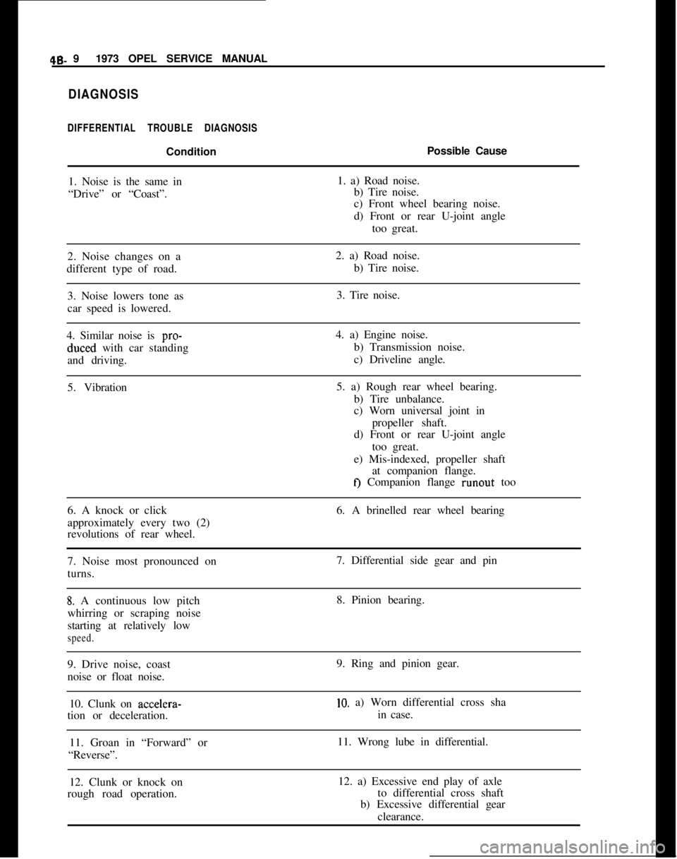
DIFFERENTIAL TROUBLE DIAGNOSISConditionPossible Cause
1. Noise is the same in1. a) Road noise.
“Drive” or “Coast”.b) Tire noise.
c) Front wheel bearing noise.
d) Front or rear U-joint angle
too great.
2. Noise changes on a2. a) Road noise.
different type of road.b) Tire noise.
3. Noise lowers tone as3. Tire noise.
car speed is lowered.
4. Similar noise is pro-4. a) Engine noise.duced with car standingb) Transmission noise.
and driving.c) Driveline angle.
5. Vibration5. a) Rough rear wheel bearing.
b) Tire unbalance.
c) Worn universal joint in
propeller shaft.
d) Front or rear U-joint angle
too great.
e) Mis-indexed, propeller shaft
at companion flange.
tJ Companion flange runout too
6. A knock or click6. A brinelled rear wheel bearing
approximately every two (2)
revolutions of rear wheel.
7. Noise most pronounced on7. Differential side gear and pin
turns.
8. A continuous low pitch8. Pinion bearing.
whirring or scraping noise
starting at relatively low
speed.9. Drive noise, coast9. Ring and pinion gear.
noise or float noise.
10. Clunk on accelera-
10. a) Worn differential cross sha
tion or deceleration.in case.
11. Groan in “Forward” or11. Wrong lube in differential.
“Reverse”.
12. Clunk or knock on12. a) Excessive end play of axle
rough road operation.to differential cross shaft
b) Excessive differential gear
clearance.
Page 294 of 625
ENGINE MECHANICAL AND MOUNTS6A- 3
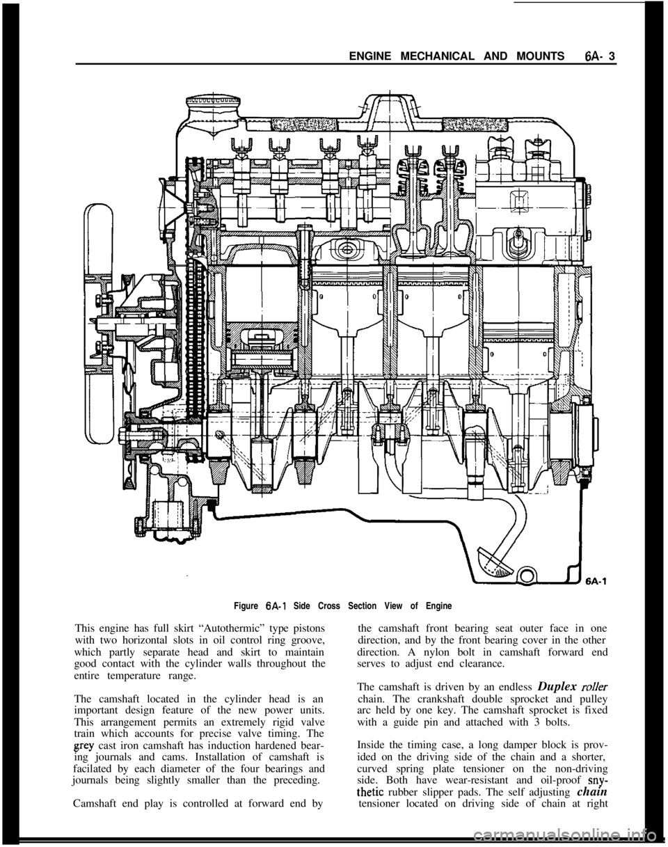
Figure 6A-1 Side Cross Section View of Engine
This engine has full skirt “Autothermic” type pistons
with two horizontal slots in oil control ring groove,
which partly separate head and skirt to maintain
good contact with the cylinder walls throughout the
entire temperature range.
The camshaft located in the cylinder head is an
important design feature of the new power units.
This arrangement permits an extremely rigid valve
train which accounts for precise valve timing. Thegray cast iron camshaft has induction hardened bear-
ing journals and cams. Installation of camshaft is
facilated by each diameter of the four bearings and
journals being slightly smaller than the preceding.
Camshaft end play is controlled at forward end bythe camshaft front bearing seat outer face in one
direction, and by the front bearing cover in the other
direction. A nylon bolt in camshaft forward end
serves to adjust end clearance.
The camshaft is driven by an endless Duplex
rollerchain. The crankshaft double sprocket and pulley
arc held by one key. The camshaft sprocket is fixed
with a guide pin and attached with 3 bolts.
Inside the timing case, a long damper block is prov-
ided on the driving side of the chain and a shorter,
curved spring plate tensioner on the non-driving
side. Both have wear-resistant and oil-proof
sny-thetic rubber slipper pads. The self adjusting chain
tensioner located on driving side of chain at right
Page 332 of 625
FUEL SYSTEM6C- 41
covered with sound deadening compound. See Fig-
ure
6C-10.7. Remove fuel tank vent hose and tiller hose. See
Figure 6C- 11.
8. Remove fuel tank attaching bolts and gauge wire
and remove tank.
Installation
1. Install tank and tighten attaching bolts.
2. Replace gauge wire. Install vent hose, making cer-
tain it is not kinked and seal vent hose hole in floor.
3. Install spare tire support attaching brackets, sup-
port panel, hold-down, and brackets.
4. Install spare tire and jack.
5. Install fuel line and rubber cap.
6. Connect battery.FUEL LINES. FUEL GAUGE TANK UNITS
All fuel lines are plastic and have an outside diameter
of
,240 inches. Unlike metal lines, plastic lines are
not flared.
When replacing a plastic line, place the line in hot
water to make it flexible. Using the old line as a
pattern, form the new line. Let the line cool com-
pletely, then route it in the same location as the old
line. To prevent chafing against the underbody, nine
(9) rubber grommets are placed at points on the line
between the fuel tank and the fuel pump. When re-
placing fuel gauge tank units, coat gasket on both
sides and first threads of attaching screws with seal-
ing compound.
CLEANING FUEL TANK
1. Remove fuel tank.
2. Empty fuel tank through filler neck.
3. Remove fuel gauge tank unit, together with suc-
tion tube and screen. Clean screen and blow out from
cover side. Flush fuel tank.
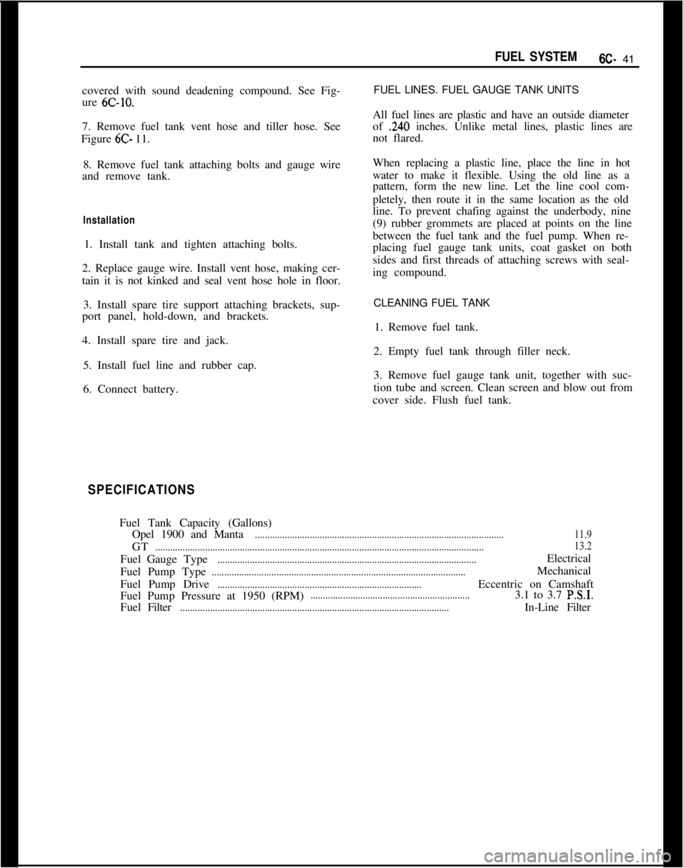
SPECIFICATIONSFuel Tank Capacity (Gallons)
Opel 1900 and Manta
....................................................................................................11.9GT
....................................................................................................................................13.2FuelGaugeType
........................................................................................................Electrical
Fuel Pump Type
......................................................................................................Mechanical
Fuel Pump Drive
..................................................................................Eccentric on Camshaft
Fuel Pump Pressure at 1950 (RPM)................................................................3.1 to 3.7 P.S.I.FuelFilter
............................................................................................................In-LineFilter
Page 368 of 625
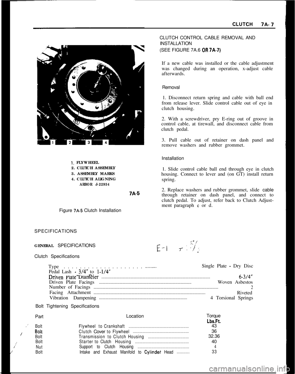
Installation1. FLYWHEEL
2. CLUTCH ASSEMBLY
3. ASSEMBLY MARKS
4. CLUTCH ALIGNING
ARBOR J-229347A-51. Slide control cable ball end through eye in clutch
housing. Connect to lever and (on GT) install return
spring.
2. Replace washers and rubber grommet, slide cable
through retainer on dash panel, and connect to
clutch pedal. To adjust, refer back to Clutch Adjust-
ment paragraph
c or d.
Figure
7A-5 Clutch Installation
SPECIFICATIONS
GENERAL SPECIFICATIONSE-l
I-‘-J- : ,“/’‘~Clutch Specifications
Type. . . . . . . . . . . . . . . . . . . .
Pedal Lash
_ 3/4” to l-1/4”-. -..-.
.........Single Plate - Dry Disc
unvenFlareuamerer.....................................................................................................6-3/4”
Driven Plate Facings
......................................................................................Woven Asbestos
Number of Facings
....................................................................................................................
2Facing Attachment
........................................................................................................Riveted
Vibration Dampening
..................................................................................4 Torsional Springs
Bolt Tightening SpecificationsCLUTCH CONTROL CABLE REMOVAL AND
INSTALLATION
(SEE FIGURE 7A.6
OR 7A-7)
If a new cable was installed or the cable adjustment
was changed during an operation, x-adjust cable
afterwards.
Removal
1. Disconnect return spring and cable with ball end
from release lever. Slide control cable out of eye in
clutch housing.
2. With a screwdriver, pry E-ring out of groove in
control cable, at tirewall, and disconnect cable from
clutch pedal.
3. Pull cable out of retainer on dash panel and
remove washers and rubber grommet.
PartLocationTorque
Lbs.Ft..’
BoltFlywheeltoCrankshaft........................................................43
/BoltClutchCovertoFlywheel....................................................36
BoltTransmissiontoClutchHousing......................................32.36;:
BoltStartertoClutchHousing..................................................40
NutSupport to Clutch Housing................................................4IBoltIntake and Exhaust Manifold to Cylindei Head............33