load capacity OPEL GT-R 1973 Service Manual
[x] Cancel search | Manufacturer: OPEL, Model Year: 1973, Model line: GT-R, Model: OPEL GT-R 1973Pages: 625, PDF Size: 17.22 MB
Page 253 of 625

48. 221973 OPEL SERVICE MANUAL
9. Position
case assembly and outer races in the car-
rier. Use a soft-faced hammer to drive the case into
the carrier until the side bearing outer races bottom
in their bores.
10. Install side bearing caps in their original location
and torque the bolts to 33
lb.ft.IN. LB. TORQUL
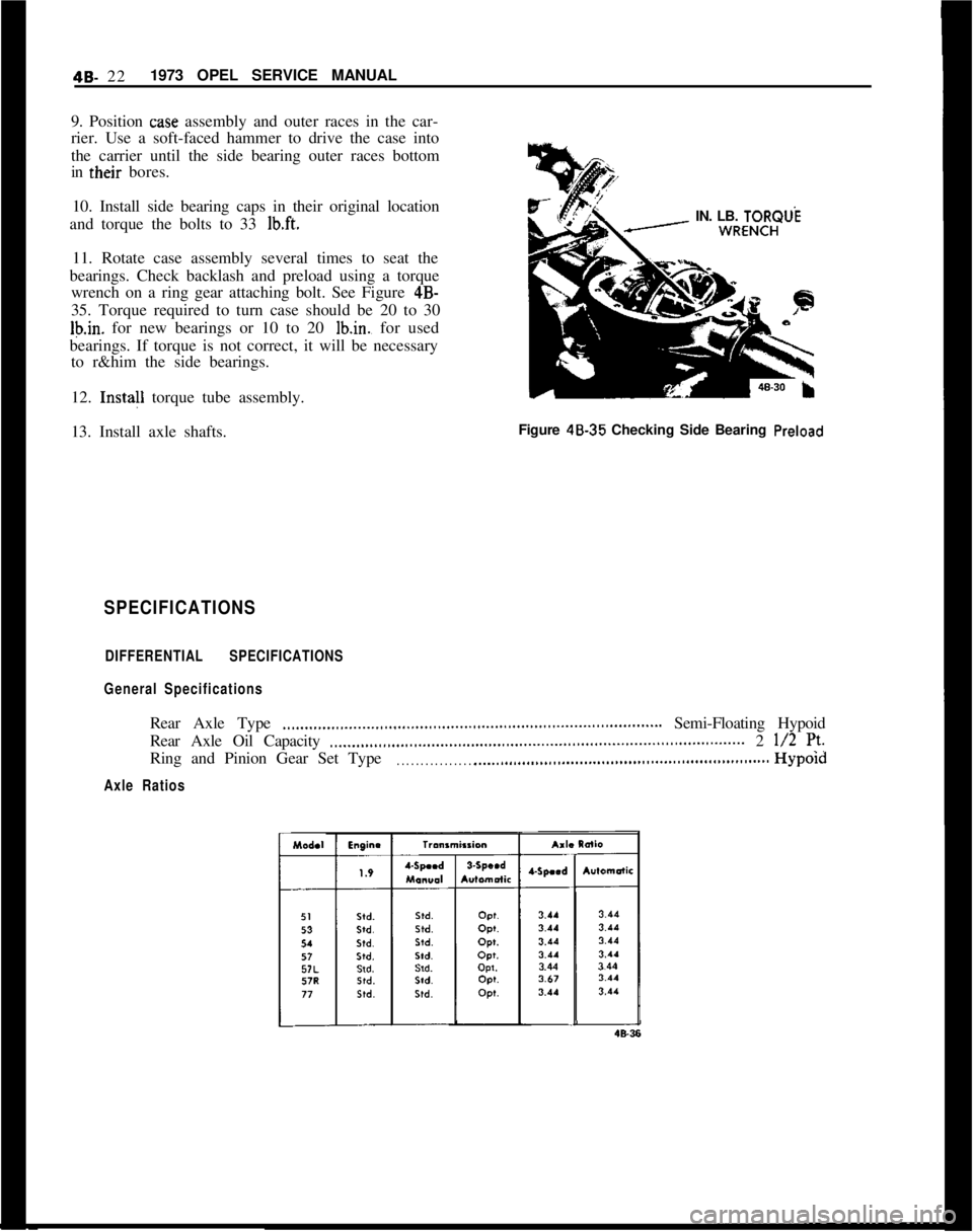
11. Rotate case assembly several times to seat the
bearings. Check backlash and preload using a torque
wrench on a ring gear attaching bolt. See Figure 4B-
35. Torque required to turn case should be 20 to 30
Ib.in. for new bearings or 10 to 20 lb.in., for used
bearings. If torque is not correct, it will be necessary
to r&him the side bearings.
12. Insta!l torque tube assembly.
13. Install axle shafts.Figure 48.35 Checking Side Bearing
Preload
SPECIFICATIONS
DIFFERENTIAL SPECIFICATIONS
General SpecificationsRear Axle Type
.,,...,,,...,,_...._..,,...,,,...,,,....,,.,...,,.,,...,,..,,,........................ Semi-Floating Hypoid
Rear Axle Oil Capacity
..____,,...,,,...,.,..,............,,..,,..,,................................................. 2 l/2 7’.Ring and Pinion Gear Set Type
. . . . . . . . . . . . . . . . . .._................................................................Hypold
Axle Ratios
Page 556 of 625

REFRIGERANT COMPONENTS ALL MODELS9a- 47
B. Connect center flexible line of gauge set to the
fitting on the valve.
C. Start engine, turn temperature control knob to full
cold position, set blower switch to Max Hi. Operate
engine for 10 minutes at 2000 RPM to stabilize sys-tem.D. With compressor operating, slowly open valve on
refrigerant can and allow refrigerant to flow into
system (through manifold gauge set) until liquid in-
dicator clears up and immediately shut off valve at
gauge set and on refrigerant can. Check weight of
can and valve assembly and record.
E. Add an additional 1 lb. of refrigerant by adding
refrigerant from the can just weighed until can is
empty. Attach another can and add refrigerant until
can and valve assembly weigh the same as recorded.
6. Close valves at refrigerant drum or
can,7. Test for leaks and make operational check of
system.
ADDING OIL TO THE SYSTEM (MAJOR
OVERHAUL)The oil in the refrigeration system does not remain
in the compressor during system operation, but cir-culates throughout the system. The compressor is
initially charged with 10 oz. of 525 viscosity oil.
After system has been in operation the oil content in
the compressor will vary depending on the engine
RPM and air conditioning load. At higher engine
RPM’s a lesser amount of oil will be retained in the
compressor reservoir. It is important that the total
system oil content does not vary from a total of10-l/2 oz. Excessive oil content will reduce cooling
capacity. Inadequate oil content may result in dam-
age to compressor moving parts.
The refrigeration system will not require adding of
oil unless there is an oil loss because of a ruptured
line, badly leaking compressor seal, replacement of
evaporator, compressor, receiver-dehydrator, or loss
due to a collision. Oil is generally added to the sys-
tem via the oil drain hole in the lower side of the
compressor for this condition. To add oil to the sys-
tem via the compressor, the compressor must be
removed. If no major loss of oil has occurred and a
component (condenser,receiver-dehydrator or
evaporator) is removed for servicing, the oil may be
added directly to the component. To add oil to a
component removed for servicing and when no ma-
jor loss has occurred, drain and measure oil in com-
ponent, then replace with a like amount. To add oil
to the system when a major loss of oil is evidenced,
or when the compressor is being serviced, remove
compressor, drain and measure oil, and replace oil
amount specified in the Oil Replacement Table.
OIL REP,‘LACEMENT TABLE
Condition
1. Major loss of oil and
a component (conden-
ser, receiver-dehydra-
tor, or evaporator)
has to be replaced.
Amount of Oil Drained
From Compressora. More than 4 oz.Amount of 525 Oil to Install
In Compressora. Amount drained from compressor,
plus amount for component
being replaced.
Evaporator
- Add 2 oz.
Condenser
- Add I oz.
Receiver-Dehydrator
- Add 1 oz.
b. Less than 4 oz.b. Install 6 oz., plus amount for
component being replaced as
shown above.
2. Compressor being
replaced with a
ser-vice replacement
compressor
- no major
oil loss.a. More than 1
l/2 oz.a. Same amount as drained from
compressor being replaced.
b. Less than 1
l/2 oz.b. Install 6 oz