ESP OPEL INSIGNIA BREAK 2017.5 Manual user
[x] Cancel search | Manufacturer: OPEL, Model Year: 2017.5, Model line: INSIGNIA BREAK, Model: OPEL INSIGNIA BREAK 2017.5Pages: 303, PDF Size: 8.46 MB
Page 216 of 303

214Driving and operatingFault messages are displayed with a
9 on the top line of the Info-Display.
Rear cross traffic alert
Additional to the rear view camera
3 212 , rear cross traffic alert warns of
cross traffic from left or right side
when driving rearwards. When cross
traffic is recognized and the rear view
camera is activated, a warning
triangle with a direction arrow K
appears on the Colour-Info-Display,
showing the direction of the traffic.
Furthermore, three beeps will sound
from the speaker on the respective
side.The radar distance sensors are
located in the rear bumper.9 Warning
The rear cross traffic alert does not
replace driver vision. Note that
objects that are outside sensors,
e.g. below the bumper or
underneath the vehicle, are not
displayed.
Pedestrians, children or animals
are not detected.
Do not reverse the vehicle by only
looking at the Info-Display and
check the surrounding behind and
around the vehicle before
reversing.
Activation
Rear cross traffic alert is
automatically activated together with
the rear view camera when reverse
gear is engaged.
Detection zones
The system sensors cover a zone of
approx. 20 metres at 90° to the left or
right side behind the vehicle. Rear cross traffic alert is active up to 10 km/ h and issues alerts within cross traffic
travelling between 0 and 36 km/h.
Deactivation
Rear cross traffic alert is deactivated together with the rear view camera
when a certain forward speed is
exceeded or if reverse gear is not
engaged for approx. 10 seconds.
Page 221 of 303

Driving and operating219If the currently displayed sign
originates from map data and the map
information changes, a new sign will
be displayed. This may lead to
detection of a new sign although no
sign on the road may have been
passed.
System limitations Traffic sign assistant may not operate properly when:
● Vehicle speed is faster than 200 km/h.
● Driving on winding or hilly roads. ● During nighttime driving.
● Weather limits visibility, such as fog, rain, or snow.
● The sensor in the windscreen is blocked by snow, ice, slush, mud,
dirt, windscreen damage or
affected by foreign items, e.g.
stickers.
● The sun is shining directly into the camera lens.
● Traffic signs are completely or partially covered or difficult to
discern.● Traffic signs are incorrectly mounted or damaged.
● Traffic signs do not comply with the Vienna Convention on Road
Signs and Signals (Wiener
Übereinkommen über
Straßenverkehrszeichen).Caution
The system is intended to help the driver within a defined speed
range to discern certain traffic
signs. Do not ignore traffic signs
which are not displayed by the
system.
The system does not discern any other than the conventional traffic
signs that might give or end a
speed limit.
Do not let this special feature
tempt you into taking risks when
driving.
Always adapt speed to the road
conditions.
The driver assistance systems do not relieve the driver from full
responsibility for vehicle
operation.
Lane keep assist
Lane keep assist helps to avoid
crashes due to unintentional lane
departures. The front camera
observes the lane markings between
which the vehicle is driving. If the
vehicle approaches a lane marking, the steering wheel is gently turned to
position the vehicle back into the lane. Turn steering wheel in same
direction, if system steering is not
sufficient. Turn steering wheel gently
into opposite direction, if lane change is intended.
When crossing a lane marking
significantly, lane keep assist starts a
visual and acoustic warning.
Unintended lane departure is
assumed
● without using turn signal● using the turn signal in the opposite direction of the lane
departure
Page 222 of 303

220Driving and operating● without braking
● without acceleration
● without active steering.
Note
The system is switched off during
detection of ambiguous lane
markings, e.g. in construction areas.
Note
The system may be switched off if it
detects lanes which are too narrow,
too wide or too curved.
ActivationThe lane keep assist is activated by
pressing a. The LED in the button
illuminates to indicate that the system
is switched on.
When the control indicator a in the
instrument cluster or in the head-up display illuminates green, the system
is ready to assist.
The system is operational at vehicle
speeds between 60 km/h and
180 km/h and if lane markings are
available.
The system gently turns the steering
wheel and the control indicator a
changes to yellow, if the vehicle
approaches a detected lane marking
without using the turn signal in that
direction.
The system alerts by flashing a
together with three chimes, from the
respective direction, if the lane is
departed significantly.
The system is only operable when a
lane marking is detected.
If the system only detects lane
markings on one side of the road, it
will only assist for this side.
Lane keep assist detects hands-free
driving. In this case a message in the
Driver Information Centre pops-up
and a chime sounds as long as lane
keep assist detects hands-free
driving.
Deactivation The system is deactivated by
pressing a; the LED in the button
extinguishes.
System limitationsThe system performance may not
operate properly when:
● Vehicle speed is out of range from 60 to 180 km/h.
● Driving on winding or hilly roads.
● During nighttime driving.
● Weather limits visibility, such as fog, rain, or snow.
Page 223 of 303
Driving and operating221● The sensor in the windscreen isblocked by snow, ice, slush, mud,dirt, windscreen damage or
affected by foreign items, e.g.
stickers.
● The sun is shining directly into the camera lens.
● Close vehicles ahead
● Banked roads
● Road edges
● Roads with poor lane markings
● Sudden lighting changes
● Vehicle modifications, e.g. tyres.
Switch off the system if the system is
disturbed by tar marks, shadows,
road cracks, temporary or
construction lane markings, or other
road imperfections.9 Warning
Always keep your attention on the
road and maintain proper vehicle
position within the lane, otherwise
vehicle damage, injury or death
could occur.
Lane keep assist does not
continuously steer the vehicle.
The system may not keep the
vehicle in the lane or give an alert,
even if a lane marking is detected.
The steering of the lane keep
assist may not be sufficient to
avoid a lane departure.
The system may not detect hands-
off driving due to external
influences (road condition and
surface, weather etc). The driver
has full responsibility to control the vehicle and is always required tokeep the hands on the steeringwheel while driving.
Using the system while towing a
trailer or on slippery roads could
cause loss of control of the vehicle
and a crash. Switch the system off.Fuel
Fuel for petrol engines Only use unleaded fuel that complies
with European standard EN 228 or E DIN 51626-1 or equivalent.
The engine is capable of running with fuel that contains up to 10% ethanol
(e.g. named E10).
Use fuel with the recommended
octane rating. A lower octane rating
can reduce engine power and torque
and slightly increases fuel
consumption.Caution
Do not use fuel or fuel additives
that contain metallic compounds
such as manganese-based
additives. This may cause engine
damage.
Page 226 of 303
224Driving and operating
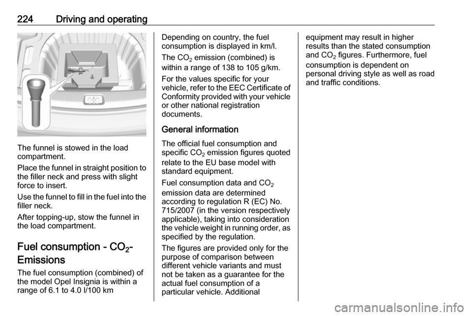
The funnel is stowed in the load
compartment.
Place the funnel in straight position to the filler neck and press with slight
force to insert.
Use the funnel to fill in the fuel into the
filler neck.
After topping-up, stow the funnel in
the load compartment.
Fuel consumption - CO 2-
Emissions
The fuel consumption (combined) of the model Opel Insignia is within a
range of 6.1 to 4.0 l/100 km
Depending on country, the fuel
consumption is displayed in km/l.
The CO 2 emission (combined) is
within a range of 138 to 105 g/km.
For the values specific for your
vehicle, refer to the EEC Certificate of
Conformity provided with your vehicle or other national registration
documents.
General information The official fuel consumption and
specific CO 2 emission figures quoted
relate to the EU base model with standard equipment.
Fuel consumption data and CO 2
emission data are determined
according to regulation R (EC) No.
715/2007 (in the version respectively
applicable), taking into consideration
the vehicle weight in running order, as specified by the regulation.
The figures are provided only for the
purpose of comparison between
different vehicle variants and must not be taken as a guarantee for the
actual fuel consumption of a
particular vehicle. Additionalequipment may result in higher
results than the stated consumption
and CO 2 figures. Furthermore, fuel
consumption is dependent on
personal driving style as well as road
and traffic conditions.
Page 228 of 303
226Driving and operatingThe permissible gross train weight
must not be exceeded. This weight is
specified on the identification plate
3 275.
Vertical coupling load The vertical coupling load is the load
exerted by the trailer on the coupling
ball. It can be varied by changing the
weight distribution when loading the
trailer.
The maximum permissible vertical
coupling load of 60 kg
(engines B20DTH: 90 kg) is specified
on the towing equipment identification plate and in the vehicle documents.
Always aim for the maximum load,
especially in the case of heavy
trailers. The vertical coupling load
should never fall below 25 kg.Rear axle load
When the trailer is coupled and the
towing vehicle fully loaded, the
permissible rear axle load (see
identification plate or vehicle
documents) may be exceeded by
70 kg (engines B20DTH: 80 kg), the
gross vehicle weight rating must not
be exceeded. If the permissible rear
axle load is exceeded, a maximum
speed of 100 km/h applies.
Towing equipmentCaution
The folding coupling ball bar
cannot be removed from the
vehicle. When driving without a
trailer, fold in the coupling ball bar.
9 Warning
Make sure that no one is in the
pivot zone of the coupling ball bar. Risk of body injury.
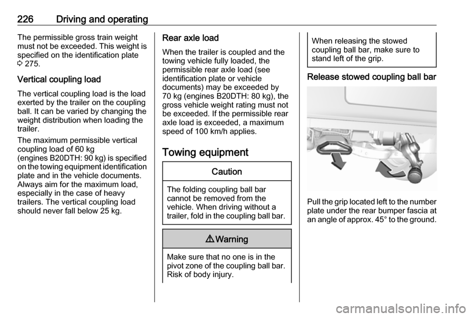
When releasing the stowed
coupling ball bar, make sure to
stand left of the grip.
Release stowed coupling ball bar
Pull the grip located left to the number
plate under the rear bumper fascia at an angle of approx. 45° to the ground.
Page 243 of 303

Vehicle care241Lamp assembly in the body
1. Remove the cover on therespective side.
2. Unscrew the two plastic securing nuts from the inside by hand.
3. Carefully withdraw tail lampassembly from recess and
remove.
4. Turn the bulb carrier anticlockwise and remove it from
the lamp assembly.
5. Remove and replace the turn signal light bulb.
6. Attach the bulb carrier to the lamp
assembly.
7. Attach the lamp assembly to the vehicle body and tighten the
securing nuts from the inside of the load compartment. Attach
cover.
Page 246 of 303

244Vehicle care4. Insert bulb holder and turnclockwise.
5. Insert left end of the lamp, slide to
the left and insert right end.
Number plate light
The number plate light is designed as
LEDs and can not be changed. In
case of defective LEDs, have them
replaced by a workshop.
Interior lights
Courtesy light, reading lights
Have bulbs replaced by a workshop.
Load compartment light
Have bulbs replaced by a workshop.
Instrument panel illumination
Have bulbs replaced by a workshop.Electrical system
Fuses Data on the replacement fuse must
match the data on the defective fuse.
There are three fuse boxes in the
vehicle:
● engine compartment
● instrument panel
● load compartment
Before replacing a fuse, turn off the
respective switch and the ignition.
A blown fuse can be recognized by its melted wire.Caution
Do not replace the fuse until the
cause of the fault has been
remedied.
Some functions are protected by
several fuses.
Fuses may also be inserted without
existence of a function.
Fuse extractor
A fuse extractor may be located in the
fuse box in the engine compartment.
Page 253 of 303
Vehicle care251Tyre designations
E.g. 215/60 R 16 95 H215:tyre width, mm60:cross-section ratio (tyre height
to tyre width), %R:belt type: RadialRF:type: RunFlat16:wheel diameter, inches95:load index e.g. 95 is equivalent to 690 kgH:speed code letter
Speed code letter:
Q:up to 160 km/hS:up to 180 km/hT:up to 190 km/hH:up to 210 km/hV:up to 240 km/hW:up to 270 km/h
Choose a tyre appropriate for the
maximum speed of your vehicle.
The maximum speed is achievable at
kerb weight with driver (75 kg) plus
125 kg payload. Optional equipment
could reduce the maximum speed of
the vehicle.
Performance 3 282.
Directional tyres
Directional tyres should be mounted
so that they rotate in the correct
direction. The proper rotation
direction is indicated by a symbol (e.g. an arrow) on the sidewall.
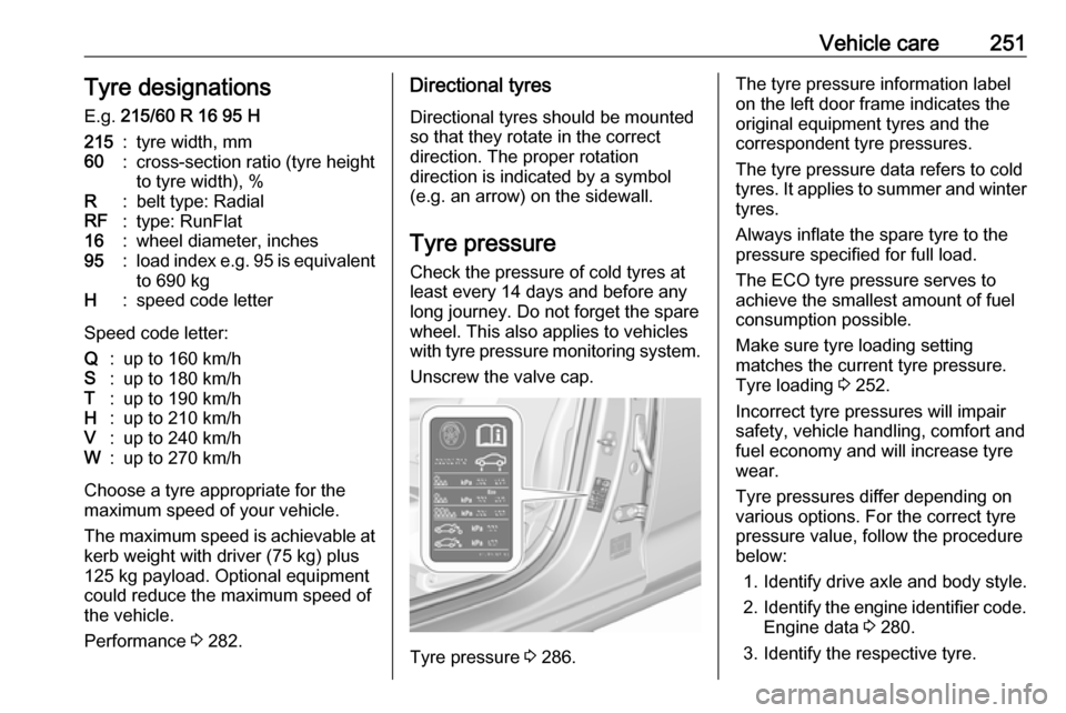
Tyre pressure
Check the pressure of cold tyres at
least every 14 days and before any
long journey. Do not forget the spare
wheel. This also applies to vehicles
with tyre pressure monitoring system.
Unscrew the valve cap.
Tyre pressure 3 286.
The tyre pressure information label
on the left door frame indicates the
original equipment tyres and the
correspondent tyre pressures.
The tyre pressure data refers to cold
tyres. It applies to summer and winter tyres.
Always inflate the spare tyre to the
pressure specified for full load.
The ECO tyre pressure serves to
achieve the smallest amount of fuel
consumption possible.
Make sure tyre loading setting
matches the current tyre pressure.
Tyre loading 3 252.
Incorrect tyre pressures will impair
safety, vehicle handling, comfort and
fuel economy and will increase tyre
wear.
Tyre pressures differ depending on
various options. For the correct tyre
pressure value, follow the procedure
below:
1. Identify drive axle and body style.
2. Identify the engine identifier code.
Engine data 3 280.
3. Identify the respective tyre.
Page 254 of 303
252Vehicle careThe tyre pressure tables show allpossible tyre combinations 3 286.
For the tyres approved for your
vehicle, refer to the EEC Certificate of Conformity provided with your vehicle
or other national registration
documents.
The driver is responsible for correct
adjustment of tyre pressure.9 Warning
If the pressure is too low, this can
result in considerable tyre warm-
up and internal damage, leading to tread separation and even to tyre
blow-out at high speeds.
9 Warning
For specific tyres the
recommended tyre pressure as
shown in the tyre pressure table may exceed the maximum tyre
pressure as indicated on the tyre.
Never exceed the maximum tyre
pressure as indicated on the tyre.
After adjusting tyre pressure, select
the according tyre loading setting on
the page Tyre load in the Driver
Information Centre, 3 104.
Temperature dependency The tyre pressure depends on the
temperature of the tyre. During
driving, tyre temperature and
pressure increase. Tyre pressure
values provided on the tyre
information label and tyre pressure
chart are valid for cold tyres, which
means at 20 °C.
The pressure increases by nearly
10 kPa for a 10 °C temperature
increase. This must be considered
when warm tyres are checked.
The tyre pressure value displayed in
the Driver Information Centre shows
the real tyre pressure. A cooled down
tyre will show a decreased value,
which does not indicate an air leak.Tyre pressure monitoring
system
The tyre pressure monitoring system
checks the pressure of all four wheels once a minute when vehicle speed
exceeds a certain limit.Caution
Tyre pressure monitoring system
warns just about low tyre pressure condition and does not replace
regular tyre maintenance by the
driver.
All wheels must be equipped with
pressure sensors and the tyres must
have the prescribed pressure.
Note
In countries where the tyre pressure monitoring system is legally
required, the use of wheels without
pressure sensors will invalidate the
vehicle operating permit.
Select the Tyre pressure monitoring
page under the Info Menu in the
Driver Information Centre 3 104.