tow bar OPEL INSIGNIA BREAK 2017.75 Manual user
[x] Cancel search | Manufacturer: OPEL, Model Year: 2017.75, Model line: INSIGNIA BREAK, Model: OPEL INSIGNIA BREAK 2017.75Pages: 323, PDF Size: 9.18 MB
Page 220 of 323

218Driving and operatingVehicle personalisation 3 126.
Info-Display 3 120.
The system is deactivated if the
vehicle is towing a trailer.
Deactivation is indicated by a
message in the Driver Information
Centre.
System limitations Occasional missed alerts can occur
under normal circumstances or in
sharp curves. The system can
temporarily alert of objects in the blind spot at specific weather conditions
(rain, hail etc). Driving on a wet road
or in the transitions from a dry area to
a wet area can cause the control
indicator F to light up, as water
splash can be interpreted as an object. Otherwise the control indicator F may illuminate due to guardrails,
signs, trees, shrubs or other immobile objects. This is normal operation and
the system does not need to be
serviced.The system may not operate properly
when:
● Ice, snow, mud, stickers, magnets, metal plates, or
anything else covers the sensors.
● Driving in heavy rainstorms. ● The vehicle had an accident or if the area surrounding the
detection sensor is damaged or
not properly repaired.
● There are extreme temperature changes.
● The vehicle is towing a trailer
In the event of a fault in the system or if the system does not work due to
temporary conditions, a message is
displayed in the Driver Information
Centre. Seek the assistance of a
workshop.
Note
After production, the system
requires a calibration. For optimal
performance, drive as soon as
possible on a straight highway road
with roadside objects, e.g. guardrails
and barriers for some distance.Panoramic view system
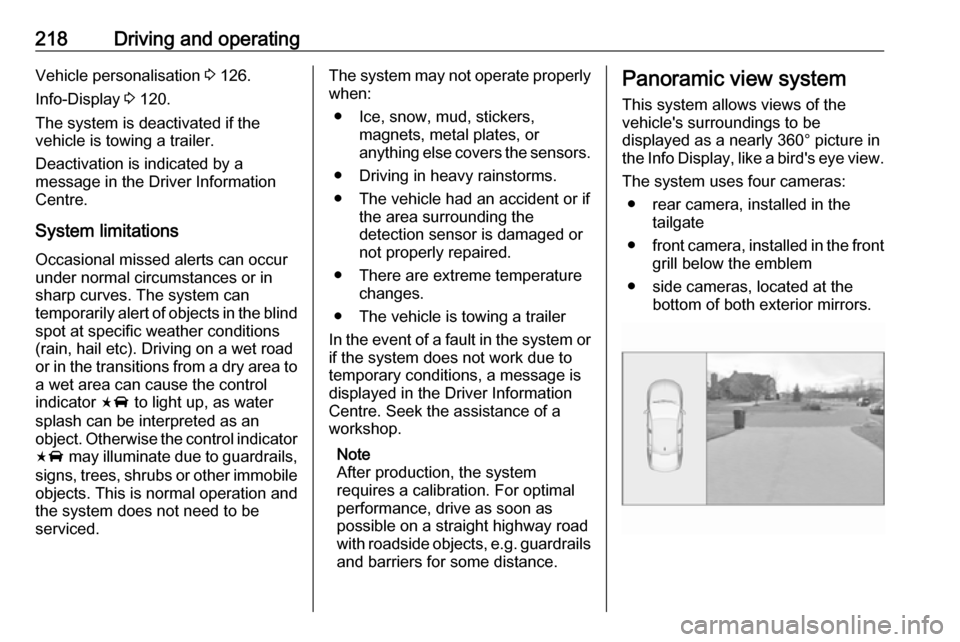
This system allows views of the
vehicle's surroundings to be
displayed as a nearly 360° picture in
the Info Display, like a bird's eye view.
The system uses four cameras: ● rear camera, installed in the tailgate
● front camera, installed in the front
grill below the emblem
● side cameras, located at the bottom of both exterior mirrors.
Page 237 of 323

Driving and operating235Trailer hitch
General information
The factory-fitted towing equipment is
folded up under the rear bumper
fascia.
Entrust retrofitting of towing
equipment to a workshop. It may be
necessary to make changes that
affect the cooling system, heat
shields or other equipment. Only use
towing equipment that has been
approved for your vehicle.
To avoid vehicle damage, the power
tailgate cannot be operated with the
electronic key when a trailer is
electrically connected.
The bulb outage detection function for trailer brake light cannot detect a
partial bulb outage, e.g. in case of four
times five watt bulbs, the function only detects lamp outage when only a
single five Watt lamp remains or none remain.
Fitting of towing equipment could
cover the opening of the towing eye.
If this is the case use the coupling ball
bar for towing.Driving characteristics and
towing tips
Before attaching a trailer, lubricate the coupling ball. However, do not do so if a stabiliser, which acts on thecoupling ball, is being used to reduce
snaking movements.
During trailer towing do not exceed a
speed of 80 km/h. A maximum speed
of 100 km/h is only appropriate if an
oscillation damper is used and the
permissible gross trailer weight does
not exceed the vehicle’s kerb weight.
For trailers with low driving stability
and caravan trailers, the use of an
oscillation damper is strongly
recommended.
If the trailer starts snaking, drive more slowly, do not attempt to correct the
steering and brake sharply if
necessary.
When driving downhill, drive in the
same gear as if driving uphill and
drive at a similar speed.
Adjust tyre pressure to the value
specified for full load 3 301.Trailer towing
Trailer loads The permissible trailer loads are
vehicle and engine-dependent
maximum values which must not be
exceeded. The actual trailer load is the difference between the actual
gross weight of the trailer and the
actual coupling socket load with the
trailer coupled.
The permissible trailer loads are
specified in the vehicle documents. In general, they are valid for gradients
up to 12%.
The permissible trailer load applies
up to the specified incline and at sea
level. Since engine power decreases
as altitude increases due to the air
becoming thinner, therefore reducing
climbing ability, the permissible gross
train weight also decreases by 10%
for every 1000 metres of altitude. The gross train weight does not have to be reduced when driving on roads with
slight inclines (less than 8%, e.g.
motorways).
Page 238 of 323

236Driving and operatingThe permissible gross train weight
must not be exceeded. This weight is
specified on the identification plate
3 288.
Vertical coupling load The vertical coupling load is the load
exerted by the trailer on the coupling
ball. It can be varied by changing the
weight distribution when loading the
trailer.
The maximum permissible vertical
coupling load of 60 kg
(engines B20DTH: 90 kg) is specified
on the towing equipment identification plate and in the vehicle documents.
Always aim for the maximum load,
especially in the case of heavy
trailers. The vertical coupling load
should never fall below 25 kg.Rear axle load
When the trailer is coupled and the
towing vehicle fully loaded, the
permissible rear axle load (see
identification plate or vehicle
documents) may be exceeded by
70 kg (engines B20DTH: 80 kg), the
gross vehicle weight rating must not
be exceeded. If the permissible rear
axle load is exceeded, a maximum
speed of 100 km/h applies.
Towing equipmentCaution
The folding coupling ball bar
cannot be removed from the
vehicle. When driving without a
trailer, fold in the coupling ball bar.
9 Warning
Make sure that no one is in the
pivot zone of the coupling ball bar. Risk of body injury.
When releasing the stowed
coupling ball bar, make sure to
stand left of the grip.
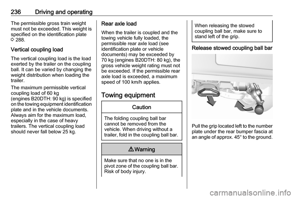
Release stowed coupling ball bar
Pull the grip located left to the number
plate under the rear bumper fascia at an angle of approx. 45° to the ground.
Page 239 of 323

Driving and operating237
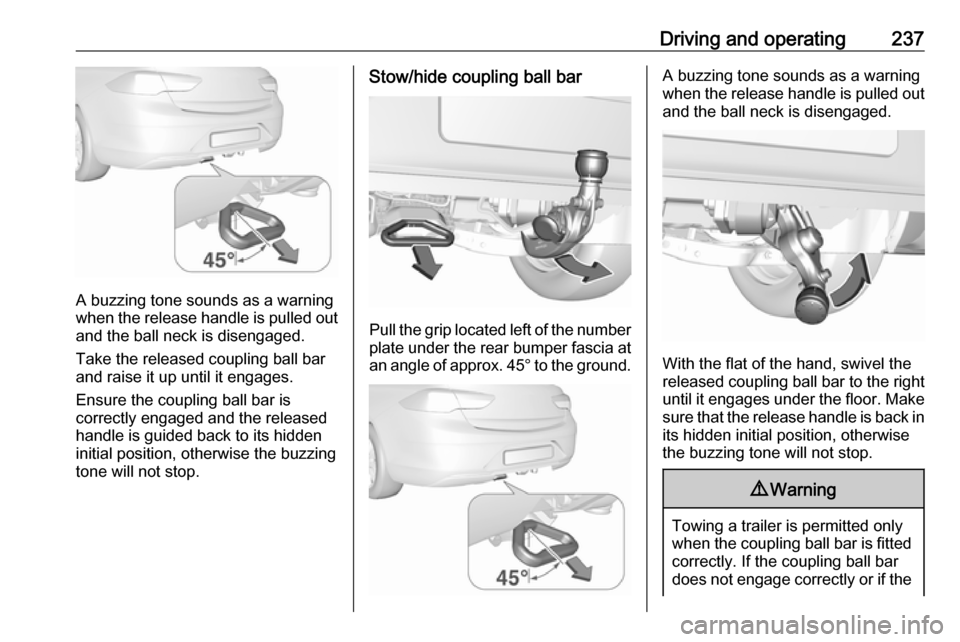
A buzzing tone sounds as a warning
when the release handle is pulled out and the ball neck is disengaged.
Take the released coupling ball bar
and raise it up until it engages.
Ensure the coupling ball bar is
correctly engaged and the released
handle is guided back to its hidden
initial position, otherwise the buzzing
tone will not stop.
Stow/hide coupling ball bar
Pull the grip located left of the number
plate under the rear bumper fascia at an angle of approx. 45° to the ground.
A buzzing tone sounds as a warning
when the release handle is pulled out and the ball neck is disengaged.
With the flat of the hand, swivel the
released coupling ball bar to the right
until it engages under the floor. Make sure that the release handle is back inits hidden initial position, otherwise
the buzzing tone will not stop.
9 Warning
Towing a trailer is permitted only
when the coupling ball bar is fitted correctly. If the coupling ball bar
does not engage correctly or if the
Page 274 of 323

272Vehicle caredecrease with the button over the
pressure indicator.
Type 2: remove tyre repair kit and
drive immediately up to 10 km, but not longer than 10 minutes. Check
tyre pressure once more. If the
tyre pressure is not obtained,
reattach the tyre repair kit and
continue the filling procedure for
10 minutes. If the prescribed tyre
pressure is still not obtained, the
tyre is too badly damaged. Seek
the assistance of a workshop.
If the pressure is obtained, correct to the prescribed tyre pressure byusing the compressor to increase
or decrease by opening the air
release valve (turn anticlockwise)
at the air filler hose.
12. Detach the tyre repair kit. Type 1: push catch on bracket to
remove sealant bottle from
bracket. Screw tyre inflation hose
to the free connection of sealant
bottle. This prevents sealant from
escaping.
Type 2: Sealant bottle can not be
removed from the compressor.Have the sealant bottle replaced
by your workshop.
13. Stow tyre repair kit in the load compartment.
14. Remove any excess sealant using a cloth.
15. Take the label indicating maximum permitted speed from
the sealant bottle and affix in the
driver's field of view.
16. Continue driving immediately so that sealant is evenly distributed
in the tyre. After driving approx.
10 km (but no more than
10 minutes), stop and check tyre
pressure. Screw compressor air
hose directly onto tyre valve.If tyre pressure is more than
1.3 bar , set it to the correct value.
Repeat the procedure until there
is no more loss of pressure.
If the tyre pressure has fallen
below 1.3 bar, the vehicle must
not be used. Seek the assistance
of a workshop.
17. Stow away tyre repair kit in the box.
18. Fix the box with the screw.
Note
The driving characteristics of the
repaired tyre is severely affected,
therefore have this tyre replaced.
If unusual noise is heard or the
compressor becomes hot, turn
compressor off for at least 30
minutes.
The built-in safety valve opens at a
pressure of 7 bar.
Note the expiry date of the kit. After
this date its sealing capability is no
longer guaranteed. Pay attention to
storage information on sealant
bottle.
Page 284 of 323

282Vehicle careIce residues, pollution and continuouswiping on dry windows will damage or
even destroy the wiper blades.
Sunroof Never clean with solvents or abrasive
agents, fuels, aggressive media
(e.g. paint cleaner, acetone-
containing solutions etc.), acidic or
highly alkaline media or abrasive
pads. Do not apply wax or polishing
agents to the sunroof.
Wheels and tyres Do not use high-pressure jet
cleaners.
Clean rims with a pH-neutral wheel
cleaner.
Rims are painted and can be treated
with the same agents as the body.
Paintwork damage
Rectify minor paintwork damage with
a touch-up pen before rust forms.
Have more extensive damage or rust
areas repaired by a workshop.Underbody
Some areas of the vehicle underbody
have a PVC undercoating while other
critical areas have a durable
protective wax coating.
After the underbody is washed, check
the underbody and have it waxed if
necessary.
Bitumen/rubber materials could
damage the PVC coating. Have
underbody work carried out by a
workshop.
Before and after winter, wash the
underbody and have the protective
wax coating checked.
Liquid gas system9 Danger
Liquid gas is heavier than air and
can collect in sink points.
Take care when performing work
at the underbody in a pit.
For painting work and when using a
drying booth at a temperature above
60 °C, the liquid gas tank must be
removed.
Do not make any modifications to the
liquid gas system.
Towing equipment
Do not clean the coupling ball bar with a steam-jet or high-pressure jet
cleaner.
Interior care
Interior and upholstery
Only clean the vehicle interior,
including the instrument panel fascia
and panelling, with a dry cloth or
interior cleaner.
Clean the leather upholstery with
clear water and a soft cloth. In case of heavy soiling, use leather care.
The instrument cluster and the
displays should only be cleaned using
a soft damp cloth. If necessary use a
weak soap solution.
Page 321 of 323

319Performance .............................. 295
Performing work ........................241
Power button .............................. 163
Power outlets ............................... 94
Power seat adjustment ................49
Power windows ............................ 39
Preheating ................................. 110
Puncture ..................................... 273
Q Quickheat ................................... 158
R
Radio Frequency Identification (RFID) ..................................... 314
Reading lights ............................ 145
Rear cross traffic alert ................223
Rear floor storage cover ..............79
Rear fog light .....................112, 143
Rear seats .................................... 54
Rear storage ................................. 79
Rear view camera ...................... 221
Rear window wiper/washer .......... 91
Recommended fluids and lubricants ........................ 285, 290
Refuelling ................................... 232
Registered trademarks ...............312
Retained power off .....................164
Reversing lights .........................144
Ride control systems ..................182
Roof .............................................. 42Roof load...................................... 85
Roof rack ..................................... 84
S Safety belts ................................... 55
Safety net .................................... 80
Seat adjustment ............................. 6 Seat belt ........................................ 8
Seat belt reminder .....................106
Seat belts ..................................... 55 Seat heating Seat heating, front .....................52
Seat heating, rear .....................54
Seat position ................................ 46
Selective catalytic reduction .......171
Service ............................... 160, 284
Service display .......................... 105
Service information ....................284
Side airbag system ......................61
Side blind zone assistant ............215
Sidelights .................................... 135
Side turn signal lights ................256
Software acknowledgement .......310
Software update ......................... 312
Spare wheel ............................... 275
Speed limiter....................... 112, 189
Speedometer ............................. 102
Starting and operating ................162
Starting off ................................... 18
Starting the engine ....................164Steering...................................... 162
Steering wheel adjustment ......9, 88
Steering wheel controls ...............88
Stop-start system........................ 166
Storage ......................................... 72
Storage compartments .................72
Sunglasses storage .....................73
Sunroof ........................................ 42
Sunvisor lights ........................... 146
Sun visors .................................... 41
Symbols ......................................... 4
T Tachometer ............................... 104
Tail lights ................................... 251
Three-point seat belt .................... 56
Tools .......................................... 262
Tow bar....................................... 235
Towing ................................ 235, 278
Towing another vehicle .............279
Towing equipment .....................236
Towing hitch installation dimensions ............................. 306
Towing the vehicle .....................278
Traction Control system ............. 182
Traction Control system off......... 110
Traffic sign assistant ...........112, 224
Trailer coupling ........................... 235
Trailer stability assist .................238
Trailer towing ............................. 235