engine OPEL INSIGNIA BREAK 2019.5 Manual user
[x] Cancel search | Manufacturer: OPEL, Model Year: 2019.5, Model line: INSIGNIA BREAK, Model: OPEL INSIGNIA BREAK 2019.5Pages: 323, PDF Size: 9.49 MB
Page 258 of 323

256Vehicle careNo.Circuit1–2–3ABS4–5–6Tailgate7Rear fog light / Front fog lights8Memory module9Heated windscreen10Seat lumbar11DC / DC battery12Heated rear window13Heated mirror14–15–16Front wiper17Power seat, passengerNo.Circuit18Sunblind19Power seat, driver20–21Sunroof22Rear wiper / Airbag23Adaptive forward lighting24–25–26Transmission control module27Ignition / Instrument panel28–29Rear view camera / Air vent30Malfunction indicator light /
Trailer31–32Camera33Seat heat front34Seat heat rearNo.Circuit35Damping / All-wheel drive36Fuel system37–38–39–40Steering wheel lock41–42–43Heated steering wheel44Headlight range adjustment45–46Engine control module47–48DC/DC converter / Air vent / E-
Boost49Rear door control module50–51–
Page 259 of 323

Vehicle care257No.Circuit52–53–54–55–56Starter57–58–59Left headlight (LED)60Cooling fan61–62–63–64–65Climate control66–67–68–No.Circuit69Right high beam (Halogen) /
Right headlight (LED)70Left high beam (Halogen)71–72Starter73–74Transmission control module75Engine control module76Exhaust reduction system77–78Horn79Washer system80–81Engine control module82–83Ignition coil84Ignition coil85PowertrainNo.Circuit86–87Diesel fuel heating88Air shutter89–90–91–92After boil pump93Electronic key system94–95Coolant pump96Diesel fuel heating97–98–99Coolant pump
After having changed defective fuses,
close the fuse box cover and press
until it engages.
If the fuse box cover is not closed
correctly, malfunction may occur.
Page 260 of 323

258Vehicle careInstrument panel fuse box
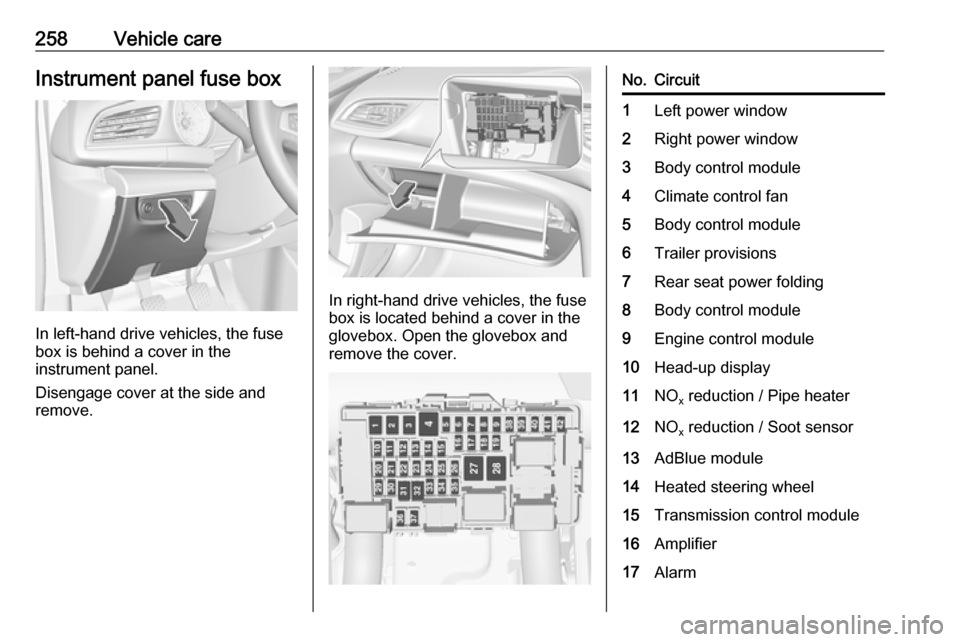
In left-hand drive vehicles, the fuse
box is behind a cover in the
instrument panel.
Disengage cover at the side and
remove.
In right-hand drive vehicles, the fuse
box is located behind a cover in the
glovebox. Open the glovebox and
remove the cover.
No.Circuit1Left power window2Right power window3Body control module4Climate control fan5Body control module6Trailer provisions7Rear seat power folding8Body control module9Engine control module10Head-up display11NO x reduction / Pipe heater12NO
x reduction / Soot sensor13AdBlue module14Heated steering wheel15Transmission control module16Amplifier17Alarm
Page 264 of 323

262Vehicle careIncorrect tyre pressures will impair
safety, vehicle handling, comfort and
fuel economy and will increase tyre
wear.
Tyre pressures differ depending on
various options. For the correct tyre
pressure value, follow the procedure
below:
1. Identify drive axle and body style.
2. Identify the engine identifier code.
Engine data 3 291.
3. Identify the respective tyre.
The tyre pressure tables show all possible tyre combinations 3 298.
For the tyres approved for your
vehicle, refer to the EEC Certificate of
Conformity provided with your vehicle or other national registration
documents.
The driver is responsible for correct
adjustment of tyre pressure.9 Warning
If the pressure is too low, this can
result in considerable tyre warm-
up and internal damage, leading to tread separation and even to tyre
blow-out at high speeds.
9 Warning
For specific tyres the
recommended tyre pressure as
shown in the tyre pressure table may exceed the maximum tyre
pressure as indicated on the tyre.
Never exceed the maximum tyre
pressure as indicated on the tyre.
After adjusting tyre pressure, select
the according tyre loading setting on
the page Tyre load in the Driver
Information Centre 3 112.
Temperature dependency The tyre pressure depends on the
temperature of the tyre. During
driving, tyre temperature and
pressure increase. Tyre pressure
values provided on the tyre
information label and tyre pressure
chart are valid for cold tyres, which means at 20 °C.
The pressure increases by nearly
10 kPa for a 10 °C temperature
increase. This must be considered
when warm tyres are checked.
The tyre pressure value displayed in
the Driver Information Centre shows
the real tyre pressure. A cooled down tyre will show a decreased value,
which does not indicate an air leak.
Tyre pressure monitoring system
The tyre pressure monitoring system
checks the pressure of all four wheels once a minute when vehicle speed
exceeds a certain limit.Caution
Tyre pressure monitoring system
warns just about low tyre pressure condition and does not replace
regular tyre maintenance by the
driver.
Page 270 of 323

268Vehicle care
2.Type 1: screw the compressor air
hose to the connection on the
sealant bottle and fit the sealant
bottle into the retainer on the
compressor.
Type 2: remove screw plug from
the compressor and from the
sealant bottle. Screw the bottle on the compressor without removing
the tinfoil from the bottle.
3. Set the compressor near the tyre in such a way that the sealant
bottle is upright.
4. Unscrew valve cap from defective
tyre.
5. Type 1: screw the filler hose to the
tyre valve.
Type 2: remove protection cap
from filler hose and screw the filler
hose to the tyre valve. The air
release valve must be closed (turn clockwise).
6. The switch on the compressor must be set to J.
7. Connect the compressor plug to the power outlet or cigarette
lighter socket.
To avoid discharging the battery, we recommend running the
engine.
Page 278 of 323

276Vehicle care● A discharged vehicle battery canalready freeze at a temperature
of 0 °C. Defrost the frozen vehicle
battery before connecting jump
leads.
● Wear eye protection and protective clothing when
handling a vehicle battery.
● Use a booster vehicle battery with the same voltage (12 V). Itscapacity (Ah) must not be muchless than that of the discharged
vehicle battery.
● Use jump leads with insulated terminals and a cross section of
at least 16 mm 2
(25 mm 2
for
diesel engines).
● Do not disconnect the discharged
vehicle battery from the vehicle.
● Switch off all unnecessary electrical consumers.
● Do not lean over the vehicle battery during jump starting.
● Do not allow the terminals of one
lead to touch those of the other
lead.● The vehicles must not come into contact with each other during
the jump starting process.
● Apply the parking brake, transmission in neutral,
automatic transmission in P.
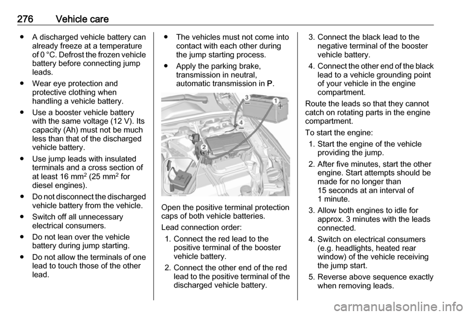
Open the positive terminal protection
caps of both vehicle batteries.
Lead connection order: 1. Connect the red lead to the positive terminal of the booster
vehicle battery.
2. Connect the other end of the red lead to the positive terminal of the
discharged vehicle battery.
3. Connect the black lead to the negative terminal of the boostervehicle battery.
4. Connect the other end of the black
lead to a vehicle grounding point
of your vehicle in the engine
compartment.
Route the leads so that they cannot
catch on rotating parts in the engine
compartment.
To start the engine: 1. Start the engine of the vehicle providing the jump.
2. After five minutes, start the other engine. Start attempts should be
made for no longer than
15 seconds at an interval of
1 minute.
3. Allow both engines to idle for approx. 3 minutes with the leads
connected.
4. Switch on electrical consumers (e.g. headlights, heated rear
window) of the vehicle receiving
the jump start.
5. Reverse above sequence exactly when removing leads.
Page 279 of 323

Vehicle care277Towing
Towing the vehicle
Wrap a cloth around the tip of a flat
screwdriver to prevent paint damage.
Insert the screwdriver in the slot at the
edge of the cap. Release the cap by
levering it out carefully.
The towing eye is stowed with the
vehicle tools 3 259.
Screw in the towing eye as far as it will
go until it stops in a horizontal
position.
Attach a tow rope – or better still a tow
rod – to the towing eye.
The towing eye must only be used for
towing and not for recovering the
vehicle.
Switch on ignition to release steering wheel lock and to permit operation of
brake lights, horn and windscreen
wiper.
Caution
Deactivate the driver assistance
systems like active emergency
braking 3 200, otherwise the
vehicle may automatically brake during towing.
Switch the selector lever to neutral.
Release the parking brake.
Caution
Drive slowly. Do not drive jerkily.
Excessive tractive force can
damage the vehicle.
When the engine is not running,
considerably more force is needed to
brake and steer.
To prevent the entry of exhaust gases from the towing vehicle, switch on the
air recirculation and close the
windows.
Vehicles with manual transmission
and All-wheel drive: If the vehicle is
towed with all four wheels on the
ground then there are no technical
Page 281 of 323

Vehicle care279Caution
Drive slowly. Do not drive jerkily.
Excessive tractive force can
damage the vehicle.
After towing, unscrew the towing eye.
Insert cap with the upper flange into
the recess and fix cap by pushing.
Appearance care
Exterior care LocksThe locks are lubricated at the factoryusing a high quality lock cylinder
grease. Use a de-icing agent only
when absolutely necessary, as this
has a degreasing effect and impairs
lock function. After using a de-icing
agent, have the locks regreased by a
workshop.
WashingThe paintwork of your vehicle is
exposed to environmental influences.
Wash and wax your vehicle regularly.
When using automatic vehicle
washes, select a programme that
includes waxing.
Bird droppings, dead insects, resin,
pollen and the like should be cleaned
off immediately, as they contain
aggressive constituents which can
cause paint damage.If using a vehicle wash, comply with
the vehicle wash manufacturer's instructions. The windscreen wiperand rear window wiper must be
switched off. Remove antenna and
external accessories such as roof
racks etc.
If you wash your vehicle by hand,
make sure that the insides of the
wheel housings are also thoroughly
rinsed out.
Clean edges and folds on opened
doors and the bonnet as well as the
areas they cover.
Clean bright metal mouldings with a
cleaning solution approved for
aluminium to avoid damages.Caution
Always use a cleaning agent with
a pH value of four to nine.
Do not use cleaning agents on hot surfaces.
Do not clean the engine compartmentwith a steam-jet or high-pressure jet
cleaner.
Page 285 of 323

Service and maintenance283Service and
maintenanceGeneral information ...................283
Service information ..................283
Recommended fluids, lubricants and parts .................................... 284
Recommended fluids and lubricants ................................ 284General information
Service information In order to ensure economical and
safe vehicle operation and to
maintain the value of your vehicle, it
is of vital importance that all
maintenance work is carried out at the proper intervals as specified.
The detailed, up-to-date service
schedule for your vehicle is available
at the workshop.
Service display 3 104.
European service intervals Maintenance of your vehicle is
required every 30,000 km or after one year, whichever occurs first.
Additional engine oil and filter change
is indicated by the engine oil life
system, when required earlier than
maintenance.
A shorter service interval can be valid
for severe driving behaviour, e.g. for
taxis and police vehicles.
The European service intervals are
valid for the following countries:Andorra, Austria, Belgium, Bosnia-
Herzegovina, Bulgaria, Croatia,
Cyprus, Czech Republic, Denmark,
Estonia, Finland, France, Germany,
Greece, Greenland, Hungary,
Iceland, Ireland, Italy, Latvia,
Liechtenstein, Lithuania,
Luxembourg, Macedonia, Malta,
Monaco, Montenegro, Netherlands,
Norway, Poland, Portugal, Romania,
San Marino, Serbia, Slovakia,
Slovenia, Spain, Sweden,
Switzerland, United Kingdom.
Service display 3 104.
International service intervals
Maintenance of your vehicle is
required every 15,000 km or after 1 year , whichever occurs first, unless
otherwise indicated in the service
display.
Severe operating conditions exist if one or more of the following
circumstances occur frequently: Cold
starting, stop and go operation, trailer operation, mountain driving, driving
on poor and sandy road surfaces,
increased air pollution, presence of
airborne sand and high dust content,
Page 286 of 323

284Service and maintenancedriving at high altitude and large
variations of temperature. Under
these severe operating conditions,
certain service work may be required more frequently than the regular
service interval.
The international service intervals are
valid for the countries which are not
listed in the European service
intervals.
Service display 3 104.
Confirmations Confirmation of service is recorded inthe Service and Warranty Booklet.
The date and mileage is completed
with the stamp and signature of the
servicing workshop.
Make sure that the Service and
warranty booklet is completed
correctly as continuous proof of
service is essential if any warranty or
goodwill claims are to be met. It is also
a benefit when selling the vehicle.Recommended fluids,
lubricants and parts
Recommended fluids andlubricants
Only use products that meet the
recommended specifications.9 Warning
Operating materials are
hazardous and could be
poisonous. Handle with care. Pay
attention to information given on
the containers.
Engine oil
Engine oil is identified by its quality
and its viscosity. Quality is more
important than viscosity when
selecting which engine oil to use. The oil quality ensures e.g. engine
cleanliness, wear protection and oil
aging control, whereas viscosity
grade gives information on the oil's
thickness over a temperature range.
Select the appropriate engine oil
based on its quality and on the
minimum ambient temperature
3 288.
Topping up engine oilCaution
In case of any spilled oil, wipe it up and dispose it properly.
Engine oils of different manufacturersand brands can be mixed as long as
they comply with the required engine
oil quality and viscosity.
Use of engine oils for all petrol
engines with only ACEA quality is
prohibited, since it can cause engine
damage under certain operating
conditions.
Select the appropriate engine oil
based on its quality and on the
minimum ambient temperature
3 288.
Additional engine oil additives
The use of additional engine oil
additives could cause damage and
invalidate the warranty.