ECU OPEL INSIGNIA BREAK 2020 Manual user
[x] Cancel search | Manufacturer: OPEL, Model Year: 2020, Model line: INSIGNIA BREAK, Model: OPEL INSIGNIA BREAK 2020Pages: 315, PDF Size: 9.45 MB
Page 87 of 315

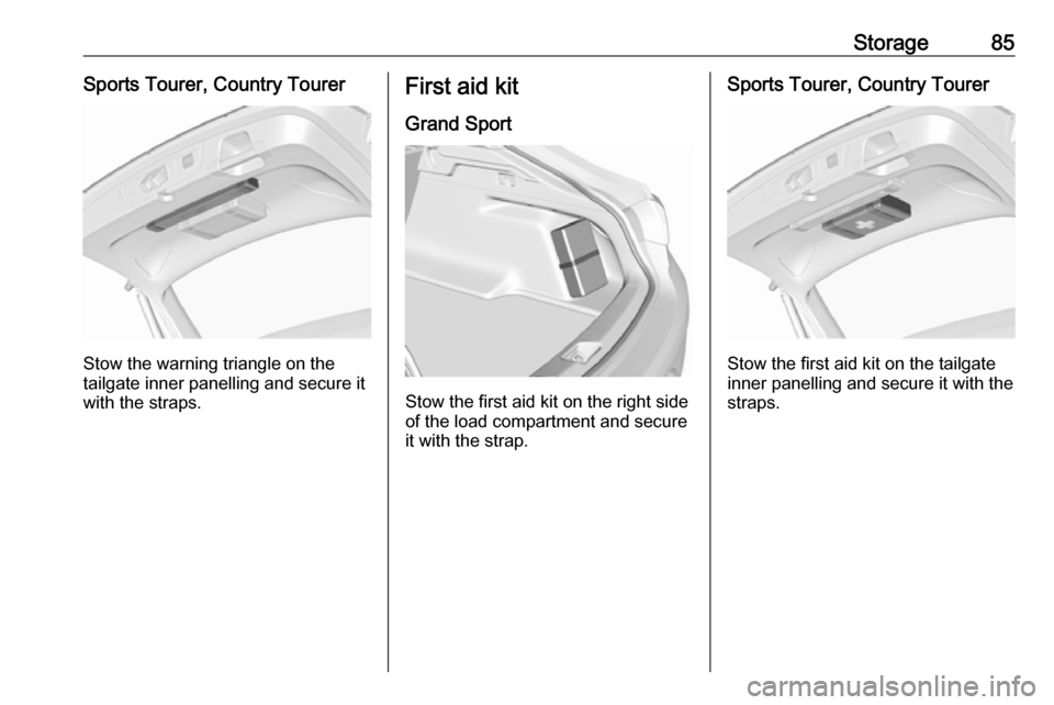
Storage85Sports Tourer, Country Tourer
Stow the warning triangle on the
tailgate inner panelling and secure it with the straps.
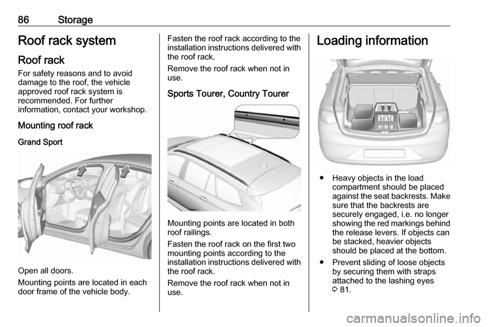
First aid kit
Grand Sport
Stow the first aid kit on the right side
of the load compartment and secure it with the strap.
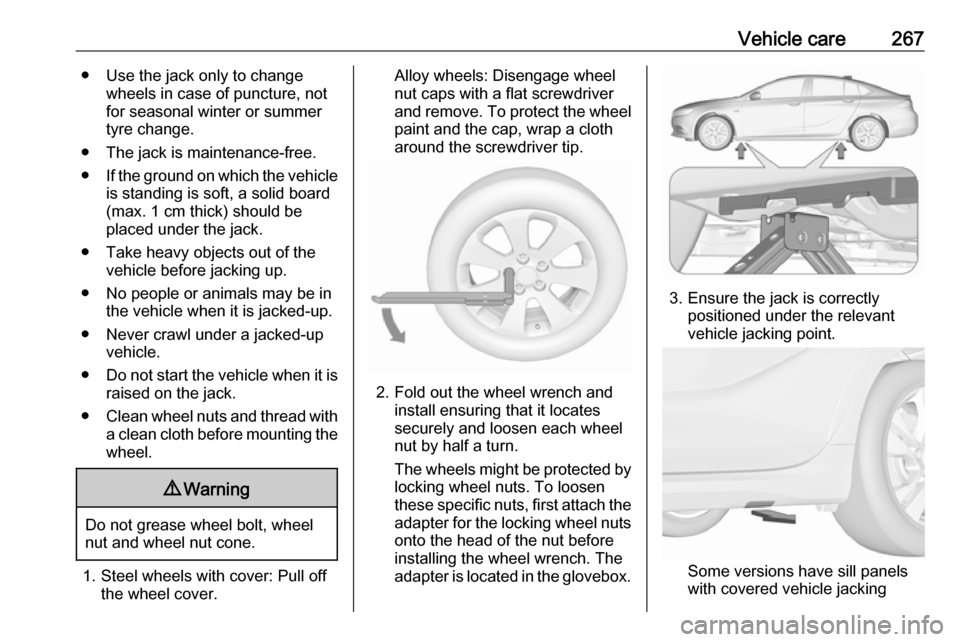
Sports Tourer, Country Tourer
Stow the first aid kit on the tailgate
inner panelling and secure it with the straps.
Page 88 of 315

86StorageRoof rack systemRoof rackFor safety reasons and to avoid
damage to the roof, the vehicle
approved roof rack system is
recommended. For further
information, contact your workshop.
Mounting roof rack
Grand Sport
Open all doors.
Mounting points are located in each
door frame of the vehicle body.
Fasten the roof rack according to the installation instructions delivered with the roof rack.
Remove the roof rack when not in use.
Sports Tourer, Country Tourer
Mounting points are located in both
roof railings.
Fasten the roof rack on the first two
mounting points according to the
installation instructions delivered with the roof rack.
Remove the roof rack when not in
use.
Loading information
● Heavy objects in the load compartment should be placed
against the seat backrests. Make
sure that the backrests are
securely engaged, i.e. no longer
showing the red markings behind
the release levers. If objects can
be stacked, heavier objects
should be placed at the bottom.
● Prevent sliding of loose objects by securing them with straps
attached to the lashing eyes
3 81.
Page 89 of 315

Storage87● Do not allow the load to protrudeabove the upper edge of the
backrests.
● Do not place any objects on the load compartment cover or the
instrument panel, and do not
cover the sensor on top of the instrument panel.
● The load must not obstruct the operation of the pedals, parking
brake and gear selector, or
hinder the freedom of movement
of the driver. Do not place any
unsecured objects in the interior.
● Do not drive with an open load compartment.9Warning
Always ensure that the load in the
vehicle is securely stowed.
Otherwise objects can be thrown
around inside the vehicle and
cause personal injury or damage
to the load or vehicle.
● The payload is the difference between the permitted grossvehicle weight (see identification
plate 3 281) and the EC kerb
weight.
To calculate the payload, enter the data for your vehicle in the
weights table at the front of this
manual.
The EC kerb weight includes
weights for the driver (68 kg),
luggage (7 kg) and all fluids (fuel
tank 90% full).
Optional equipment and
accessories increase the kerb
weight.
● Driving with a roof load increases
the sensitivity of the vehicle to
cross-winds and has a
detrimental effect on vehicle
handling due to the vehicle's
higher centre of gravity.
Distribute the load evenly and secure it properly with retaining
straps. Adjust the tyre pressure
and vehicle speed according to
the load conditions. Check and
retighten the straps frequently.
Do not drive faster than
120 km/h.The permissible roof load is
100 kg. The roof load is the
combined weight of the roof rack and the load.
Page 169 of 315

Driving and operating167Steering wheel paddles
Move selector lever out of position D
towards the left in position M.
Manual mode M can be activated
from position D in each driving
situation and speed.
Pull steering wheel paddles to select
gears manually.
Pull right paddle + to shift to a higher
gear.
Pull left paddle - to shift to a lower
gear.
Multiple pulls allow gears to be
skipped.
The selected gear is indicated in the
instrument cluster.
Temporary manual mode in drive
mode D
Manual paddle shifting is also
possible in automatic mode D. Upon
completion of manual shifting
operation, transmission changes to
automatic mode D after a defined
time.
To interrupt manual mode and return
to D, do one of the following:
● Press + paddle for 1 second.
● Move selector lever towards the left to manual mode and back to
position D.
If the vehicle is at a standstill and
engine is idling, the transmission will
remain in temporary manual mode. It
changes to automatic mode when
accelerator pedal is operated for a
defined time, and no paddle shifting
at the steering wheel is performed.
General
If a higher gear is selected when
vehicle speed is too low, or a lower
gear when vehicle speed is too high,the shift is not executed. This can
cause a message in the Driver
Information Centre.
In manual mode, no automatic
shifting to a higher gear takes place
at high engine revolutions, except
activating the kickdown function.
Gear shift indication
The symbol R or S with a number
beside it is indicated when gear
shifting is recommended for fuel
saving reasons.
Shift indication appears only in
manual mode.
Electronic driving programmes
● When SPORT mode is engaged,
the vehicle shifts at higher engine speeds (unless cruise control is
on).
SPORT mode 3 176.
Page 245 of 315

Vehicle care2432. Unscrew the two plastic securingnuts from the inside by hand.
3. Carefully withdraw light assembly from recess and remove. Take
care that the cable is not being
pulled off.
4. Turn the turn light bulb socket anticlockwise and remove it from
the light assembly.
5. Remove and replace the turn light
bulb.
6. Attach the bulb socket to the light assembly.
7. Attach the light assembly to the vehicle body and tighten the
securing nuts from the inside of
the load compartment. Attach
cover.
Light assembly in the tailgate
1. Release the cover in the tailgate and remove it.
Page 246 of 315

244Vehicle care
2. Unscrew the plastic securing nutby hand.
3. Carefully withdraw light assemblyfrom recess and remove. Take
care that the cable is not being
pulled off.
4. Turn the bulb socket anticlockwise and remove it from
the light assembly.
Rear fog light ( 1)
Reverse light ( 2)
5. Detach the bulb from the bulb socket and replace the bulb.
Rear fog light
Page 248 of 315

246Vehicle careLight assembly in the tailgate
1. Release the cover in the tailgateand remove it.
2. Unscrew the plastic securing nutby hand.
3. Carefully withdraw the lightassembly from the recess and
remove. Take care that the cable
is not being pulled off.
4. Turn the bulb socket anticlockwise and remove it from
the light assembly.
Rear fog light ( 1)
Reverse light ( 2)
5. Detach the bulb from the bulb socket and replace the bulb.
Rear fog light
Page 255 of 315

Vehicle care253No.Circuit18Body control module19AdBlue module20Body control module21Body control module22Body control module23Electric steering wheel lock24Airbag25Diagnostic connector26Power outlet load compartment27EBCM valve28Police provision29–30–31Steering wheel controls32Ignition switch33Climate control34Central gateway moduleNo.Circuit35AUX / USB connector36Wireless charger37Rear wiper38Emergency call39Display40Parking assist41Overhead console42Infotainment SystemVehicle tools
Tools
Vehicles with spare wheel
The jack with wheel wrench, the tools,
an extension bolt for securing a
damaged wheel and the towing eye
are placed in the tool box below the
spare wheel in the load compartment.
Spare wheel 3 265.
Page 268 of 315

266Vehicle careOnly mount one temporary spare
wheel. Do not drive faster than
80 km/h. Take curves slowly. Do not
use for a long period of time.Caution
The use of a spare wheel that is smaller than the other wheels or in
combination with winter tyres
could affect driveability. Have the defective tyre replaced as soon as
possible.
Caution
If driving with a temporary spare
wheel, active emergency braking
has to deactivated.
The spare wheel is located in the load
compartment beneath the floor
covering.
To remove: 1. Open the floor cover.
2. The spare wheel is secured with a
wing nut. Unscrew the wing nut
and take out the spare wheel.
Under the spare wheel there is the
box with vehicle tools.
3. When, after a wheel change, no wheel is placed in the spare wheel
well, secure the tool box by
tightening the wing nut as far as it will go and close floor cover.
4. After wheel change back to full size wheel, place the spare wheel
outside up in the well and secure
with the wing nut.
Only mount one temporary spare
wheel. The permissible maximum
speed on the label on the temporary
spare wheel is only valid for the
factory-fitted tyre size.
Fitting the spare wheel Make the following preparations and
observe the following information:
● Park the vehicle on a level, firm and non-skid surface. The front
wheels must be in the straight-
ahead position.
● Apply the parking brake and engage first gear, reverse gear or
P .
● Remove the spare wheel.
● Never change more than one wheel at once.
Page 269 of 315

Vehicle care267● Use the jack only to changewheels in case of puncture, not
for seasonal winter or summer
tyre change.
● The jack is maintenance-free.
● If the ground on which the vehicle
is standing is soft, a solid board
(max. 1 cm thick) should be
placed under the jack.
● Take heavy objects out of the vehicle before jacking up.
● No people or animals may be in the vehicle when it is jacked-up.
● Never crawl under a jacked-up vehicle.
● Do not start the vehicle when it is
raised on the jack.
● Clean wheel nuts and thread with
a clean cloth before mounting the wheel.9 Warning
Do not grease wheel bolt, wheel
nut and wheel nut cone.
1. Steel wheels with cover: Pull off the wheel cover.
Alloy wheels: Disengage wheel
nut caps with a flat screwdriver
and remove. To protect the wheel paint and the cap, wrap a cloth
around the screwdriver tip.
2. Fold out the wheel wrench and install ensuring that it locates
securely and loosen each wheel
nut by half a turn.
The wheels might be protected by
locking wheel nuts. To loosen
these specific nuts, first attach the adapter for the locking wheel nuts
onto the head of the nut before
installing the wheel wrench. The
adapter is located in the glovebox.
3. Ensure the jack is correctly positioned under the relevant
vehicle jacking point.
Some versions have sill panels
with covered vehicle jacking