ignition OPEL KADETT 1991 Electronic Workshop Manual
[x] Cancel search | Manufacturer: OPEL, Model Year: 1991, Model line: KADETT, Model: OPEL KADETT 1991Pages: 1070, PDF Size: 41.39 MB
Page 1026 of 1070
Downloaded from www.Manualslib.com manuals search engine Gas Analysis
Diagnostics using a 4 Gas Analyser
Before attempting to perform any diagnostics using a 4 gas analyser, it is important to
understand the equipment and the results obtained.
We shall begin with explaining the different gases tested :
Hydrocarbons (HC)Hydrocarbons are unburned or partially burnt fuel particles. High levels of HC,
measured in PPM (parts per million) in the exhaust gases, is usually due to
malfunctions in the ignition or fuel systems.
Carbon Monoxide (CO)Carbon monoxide is formed when there is insufficient oxygen present during
combustion and is measured as a percentage of exhaust gases. (CO - one part carbon
to one part oxygen) The most common cause of high CO is incorrect adjustment of
fuel mixtures. Refer to the relevant manufacturers manuals for correct setting
procedures.
Carbon Dioxide CO2CO2 - one part carbon to two parts oxygen. The greater the percentage of CO2 in the
exhaust gases, the more efficient the running of the engine, ideal specification for a 4
cylinder engine is between 13 and 16 %. If the CO2 level dropped too low, this would
indicate an incorrect air fuel mixture either caused by malfunctions in the
management system or incorrect adjustments.
Oxygen (O2)Oxygen is measured as a percentage of the exhaust gases and should be between 1 -
1.5% indicating an efficient combustion and air fuel mixture. Whilst adjustments are
being performed, it is important to note the changes in O2, as a sharp change of
between 0.5 - 1.0 % and 1.0 - 0.5 % will indicate the cross-over point from a rich or
lean mixture respectively. O2 measurement is also useful in detecting leaks and
misfiring as well as the efficiency of combustion.
Oxides of Nitrogen (Nox)Engines use O2 in the combustion process and exhaust Nitrogen (N2). This exhausted
N2 is exposed to high temperatures during the combustion process and is converted to
Oxides of Nitrogen (NOx) when that temperature exceeds approx. 1370 degrees
Celsius. Although NOx compounds do not directly affect the efficiency of an engine,
they are responsible for smog when combined with HC. Part of the solution to
minimise NOx is the catalytic converter and the exhaust gas recirculation process.
Page 1027 of 1070
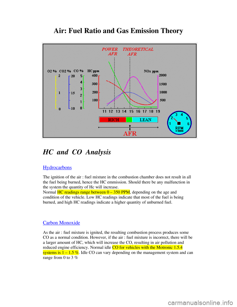
Downloaded from www.Manualslib.com manuals search engine Air: Fuel Ratio and Gas Emission Theory
HC and CO Analysis
HydrocarbonsThe ignition of the air : fuel mixture in the combustion chamber does not result in all
the fuel being burned, hence the HC emmission. Should there be any malfunction in
the system the quantity of Hc will increase.
Normal HC readings range between 0 – 350 PPM, depending on the age and
condition of the vehicle. Low HC readings indicate that most of the fuel is being
burned, and high HC readings indicate a higher quantity of unburned fuel.
Carbon MonoxideAs the air : fuel mixture is ignited, the resulting combustion process produces some
CO as a normal condition. However, if the air : fuel mixture is incorrect, there will be
a larger amount of HC, which will increase the CO, resulting in air pollution and
reduced engine efficiency. Normal idle CO for vehicles with the Motronic 1.5.4systems is 1 – 1.5 %. Idle CO can vary depending on the management system and can
range from 0 to 3 %
Page 1034 of 1070

Downloaded from www.Manualslib.com manuals search engine CONTENTS
1.0 PRODUCT DESCRIPTION
2.0 FEATURES
3.0 PRODUCT IDENTIFICATION AND APPLICATION
4.0 SPECIFICATION
4.1 Electrical
4.2 Environmental
4.3 Fuel delivery
5.0 CONNECTIONS
6.0 SPARK TIMING
6.1 Distributor bypass operation
6.2 Engine speed and crankshaft
position measurement
6.3 Engine load measurement
6.4 Advance angle look-up
6.5 Ignition firing delay calculation
6.6 Dwell time calculation
6.7 Engine water temperature measurement
7.0 FUEL INJECTION
7.1 Air mass to fuel mass ratio
7.2 Air mass measurement
7.3 Speed density concept
7.4 Fuel metering
7.5 Continuous fuel flow rate
7.6 Injector opening and closing times
7.7 Injection timing
7.8 Injection duration
7.9 Correction factors
7.9.1 Injection hardware deficiencies
7.9.2 Engine operating conditions
7.9.3 Intake air temperature
7.9.4 Engine temperature
7.9.5 Cold starting conditions
7.9.6 Post-start and warm-up conditions
7.9.7 Acceleration conditions
7.9.8 Deceleration lean-out conditions
Page 1035 of 1070

Downloaded from www.Manualslib.com manuals search engine 7.9.9 Coasting conditions
7.9.10 Flooded engine conditions
7.9.11 Full load operation
8.0 IDLE SPEED
9.0 IMMOBILISER OPERATION
10.0 DEFAULT MODE SELECTION
11.0 DIAGNOSTICS
11.1 Diagnostic codes
11.2 Volt- and ohmmeter
11.2.1 Battery voltage
11.2.2 Ignition voltage
11.2.3 TPS supply voltage
11.2.4 TPS input signal voltage
11.2.5 CO potentiometer supply voltage
11.2.6 MAP sensor supply voltage
11.2.7 MAP sensor signal voltage
11.2.8 Timing map selector
11.2.9 Fuel mixture selector
11.2.10 EWT sensor
11.2.11 MAT sensor
11.3 Fault finding
11.4 D-TEQ200 PC based tester
11.4.1 Description
11.4.2 Installation
11.4.3 Operation
11.5 C-TEQ200 component tester
11.5.1 Description
11.5.2 Operation
Page 1039 of 1070
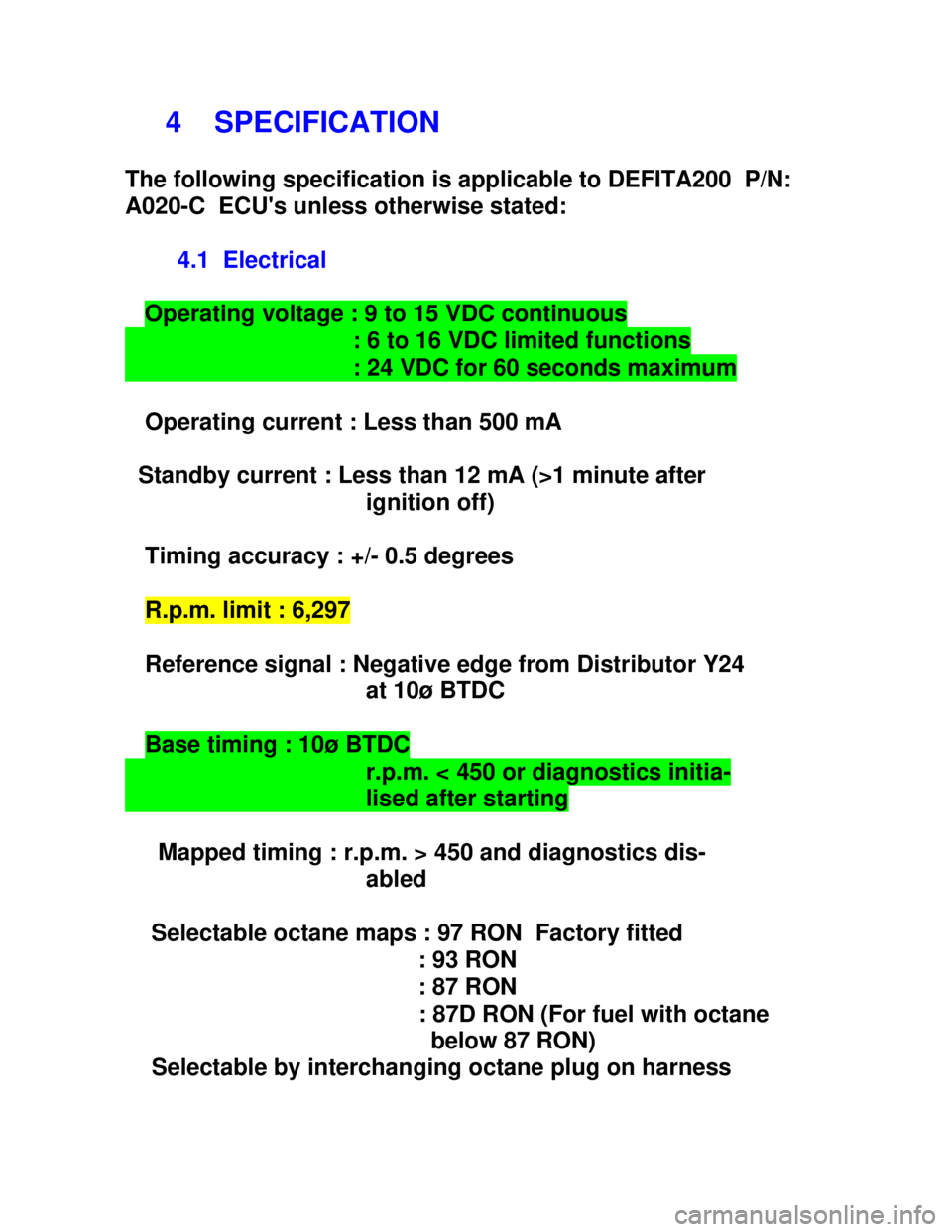
Downloaded from www.Manualslib.com manuals search engine 4 SPECIFICATION
The following specification is applicable to DEFITA200 P/N:
A020-C ECU's unless otherwise stated:
4.1 Electrical
Operating voltage : 9 to 15 VDC continuous : 6 to 16 VDC limited functions : 24 VDC for 60 seconds maximum
Operating current : Less than 500 mA
Standby current : Less than 12 mA (>1 minute after
ignition off)
Timing accuracy : +/- 0.5 degrees
R.p.m. limit : 6,297
Reference signal : Negative edge from Distributor Y24
at 10ø BTDC
Base timing : 10ø BTDC r.p.m. < 450 or diagnostics initia- lised after starting
Mapped timing : r.p.m. > 450 and diagnostics dis-
abled
Selectable octane maps : 97 RON Factory fitted
: 93 RON
: 87 RON
: 87D RON (For fuel with octane
below 87 RON)
Selectable by interchanging octane plug on harness
Page 1043 of 1070
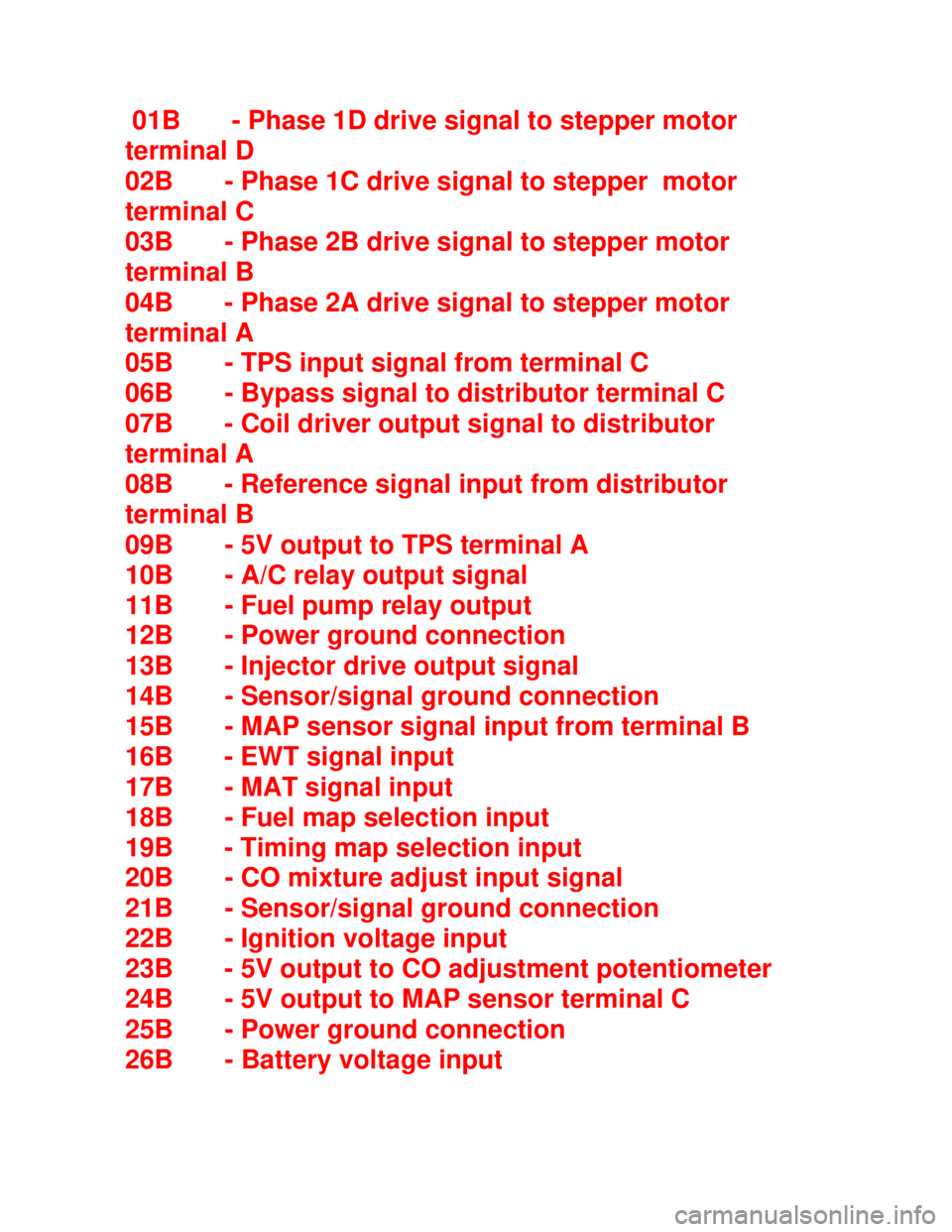
Downloaded from www.Manualslib.com manuals search engine 01B - Phase 1D drive signal to stepper motor
terminal D
02B - Phase 1C drive signal to stepper motor
terminal C
03B - Phase 2B drive signal to stepper motor
terminal B
04B - Phase 2A drive signal to stepper motor
terminal A
05B - TPS input signal from terminal C
06B - Bypass signal to distributor terminal C
07B - Coil driver output signal to distributor
terminal A
08B - Reference signal input from distributor
terminal B
09B - 5V output to TPS terminal A
10B - A/C relay output signal
11B - Fuel pump relay output
12B - Power ground connection
13B - Injector drive output signal
14B - Sensor/signal ground connection
15B - MAP sensor signal input from terminal B
16B - EWT signal input
17B - MAT signal input
18B - Fuel map selection input
19B - Timing map selection input
20B - CO mixture adjust input signal
21B - Sensor/signal ground connection
22B - Ignition voltage input
23B - 5V output to CO adjustment potentiometer
24B - 5V output to MAP sensor terminal C
25B - Power ground connection
26B - Battery voltage input
Page 1044 of 1070

Downloaded from www.Manualslib.com manuals search engine 6 SPARK TIMING
Spark timing and fuel injection for DEFITA200 ECU's is
calculated by a central processing unit and are based on:
I - MAP
II - EWT
III - Battery voltage
IV - Crankshaft position
V - Engine speed
VI - Throttle position
The optimum timing advance curves for a given engine are
determined by running the engine on an engine dynamometer
under any combination of the above-mentioned conditions.
This process is known as mapping the engine. The mapping is
further refined by extensive driving tests.
The mapped data regarding the engine is stored in a ROM
(Read Only Memory) within the ECU.
The following processes take place when calculating the
advance angle:
I - engine speed and crankshaft position measurement
II - engine load measurement
III - advance angle look-up
IV - ignition firing delay calculation
Page 1045 of 1070
Downloaded from www.Manualslib.com manuals search engine 6.1 Distributor bypass operation
At engine speeds below 450 r.p.m. the ECU does not control
the firing angle. The ECU keeps the bypass line to terminal
C of the distributor low for engine speeds below 450 r.p.m.
The spark advance for the vehicle is set to 10ø BTDC by the
distributor, while the engine speed is below 450 r.p.m..
Above 450 r.p.m. the ECU takes the bypass line high (+5
volt) and takes over control of the spark advance as de-
scribed below.
6.2 Engine speed and crankshaft position measurement
Engine speed is calculated by measuring the period from one
negative edge to the next negative edge of the distributor
reference signal. The reference signals are separated by
180 degrees.
The distributor generates a signal as shown in the reference
and ignition waveform diagram. The time taken for the crank-
shaft to rotate from 10ø BTDC to the next 10ø BTDC marker
is measured. Knowing the time it takes the crankshaft to
rotate through 180ø it is possible to calculate the current
engine speed in degrees per second (ø/s). Crankshaft posi-
tion is obtained by sensing the falling edges of the refer-
ence signal.
Page 1047 of 1070

Downloaded from www.Manualslib.com manuals search engine 6.5 Ignition firing delay calculation
The advance angle obtained from the look-up matrix is sub-
tracted from the 10ø BTDC marker on the distributor shaft to
obtain the firing angle delay.
Example: Advance angle = -20ø on next cycle
Marker position = -10ø
Firing angle delay = 180ø-(-10ø)-20ø
= 170ødelay
Having determined the engine speed previously in degrees per
second it is now possible to calculate the delay time after
the BTDC marker that corresponds with the required advance
angle.
Example: Crankshaft speed = 5,400 r.p.m.
Distributor speed = 2,700 r.p.m.
= 2,700 / 60 r.p.s.
= 45 r.p.s.
= 45x360 ø/s
Crankshaft speed = 2x45x360 ø/s
= 30,400 ø/s
170ø rotation delay = 170 / 30,400 s
= 5.59 milli-second delay
Page 1048 of 1070
Downloaded from www.Manualslib.com manuals search engine 6.6 Dwell time calculation
Dwell time is the time during which the battery voltage must
be applied to the ignition coil's primary winding prior to
an ignition pulse. The correct dwell time is important to
ensure constant spark energy.
The correct dwell time depends on the battery voltage. A
look-up matrix contains dwell time versus battery voltage.
The prevailing battery voltage is measured and compared with
the voltages stored in the dwell look-up matrix. The corre-
sponding dwell time is used to energise the ignition coil.
6.7 Engine water temperature measurement
EWT measurement is accomplished by a NTC (Negative
Temperature Coefficient) sensor mounted on the engine block.
The base advance angles are increased with decreasing
engine temperatures. This is necessary because it takes
longer to reach maximum cylinder pressure after ignition
when an engine is cold. Typical additional advance required
for an engine at -20ø Celsius ranges from 3ø to 8ø with
respect to an engine operating at 100ø Celsius.