change wheel OPEL KARL 2019 Manual user
[x] Cancel search | Manufacturer: OPEL, Model Year: 2019, Model line: KARL, Model: OPEL KARL 2019Pages: 191, PDF Size: 5.51 MB
Page 42 of 191
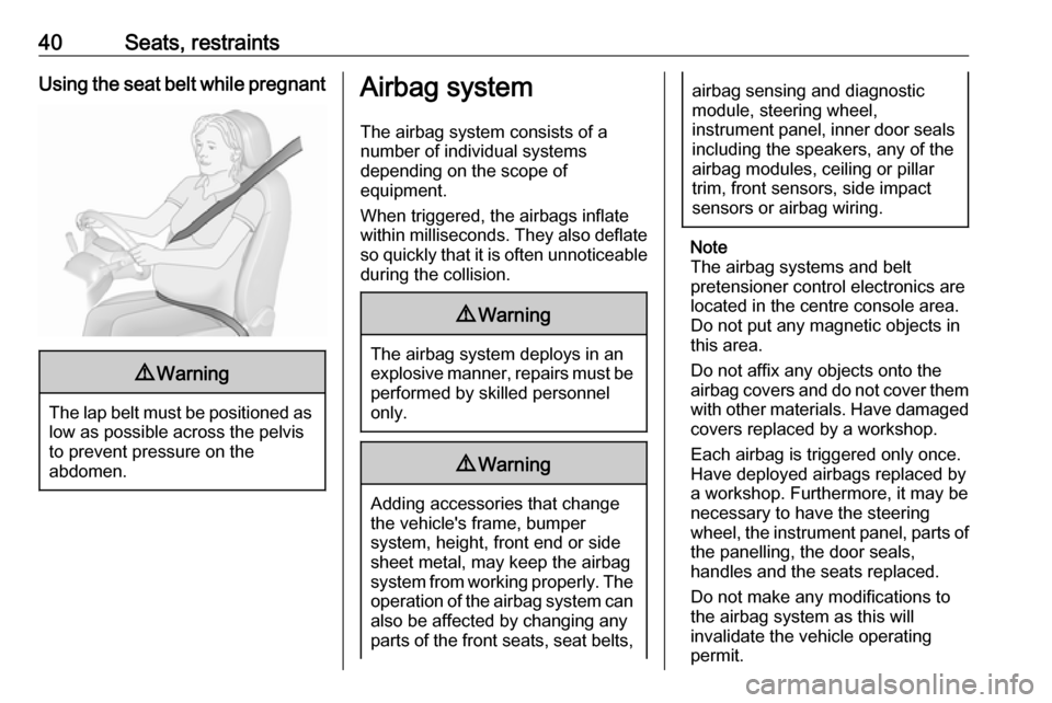
40Seats, restraintsUsing the seat belt while pregnant9Warning
The lap belt must be positioned as
low as possible across the pelvis
to prevent pressure on the
abdomen.
Airbag system
The airbag system consists of a
number of individual systems
depending on the scope of
equipment.
When triggered, the airbags inflate
within milliseconds. They also deflate
so quickly that it is often unnoticeable
during the collision.9 Warning
The airbag system deploys in an
explosive manner, repairs must be performed by skilled personnel
only.
9 Warning
Adding accessories that change
the vehicle's frame, bumper
system, height, front end or side
sheet metal, may keep the airbag
system from working properly. The operation of the airbag system can
also be affected by changing any
parts of the front seats, seat belts,
airbag sensing and diagnostic
module, steering wheel,
instrument panel, inner door seals including the speakers, any of the
airbag modules, ceiling or pillar
trim, front sensors, side impact
sensors or airbag wiring.
Note
The airbag systems and belt
pretensioner control electronics are
located in the centre console area.
Do not put any magnetic objects in
this area.
Do not affix any objects onto the
airbag covers and do not cover them with other materials. Have damagedcovers replaced by a workshop.
Each airbag is triggered only once.
Have deployed airbags replaced by
a workshop. Furthermore, it may be
necessary to have the steering
wheel, the instrument panel, parts of
the panelling, the door seals,
handles and the seats replaced.
Do not make any modifications to
the airbag system as this will
invalidate the vehicle operating
permit.
Page 54 of 191
52StorageStorageStorage compartments................52
Glovebox ................................... 52
Cupholders ................................ 52
Centre console storage .............53
Load compartment .......................53
Load compartment cover ...........55
Rear floor storage cover ............56
Warning triangle ........................56
First aid kit ................................. 57
Roof rack system .........................57
Roof rack ................................... 57
Loading information .....................58Storage compartments9Warning
Do not store heavy or sharp
objects in the storage
compartments. Otherwise, the
storage compartment lid could
open and vehicle occupants could be injured by objects being thrown
around in the event of hard
braking, a sudden change in
direction or an accident.
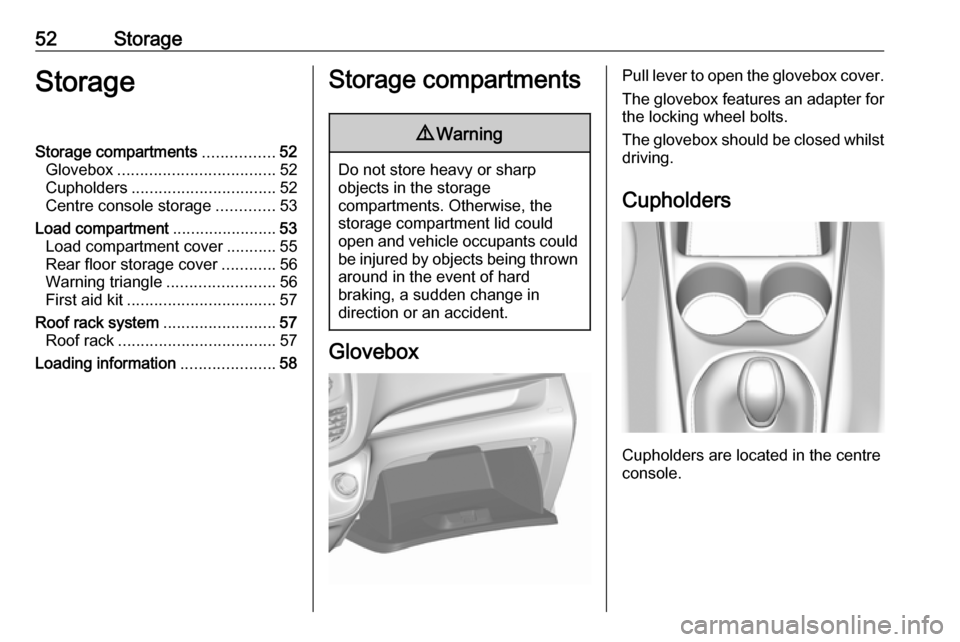
Glovebox
Pull lever to open the glovebox cover.
The glovebox features an adapter for
the locking wheel bolts.
The glovebox should be closed whilst driving.
Cupholders
Cupholders are located in the centre
console.
Page 58 of 191
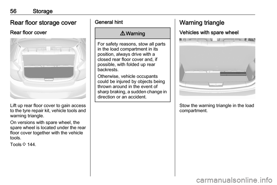
56StorageRear floor storage coverRear floor cover
Lift up rear floor cover to gain access
to the tyre repair kit, vehicle tools and
warning triangle.
On versions with spare wheel, the
spare wheel is located under the rear
floor cover together with the vehicle
tools.
Tools 3 144.
General hint9 Warning
For safety reasons, stow all parts
in the load compartment in its
position, always drive with a
closed rear floor cover and, if
possible, with folded up rear
backrests.
Otherwise, vehicle occupants
could be injured by objects being
thrown around in the event of
sharp braking, a sudden change in direction or an accident.
Warning triangle
Vehicles with spare wheel
Stow the warning triangle in the load
compartment.
Page 69 of 191
Instruments and controls67
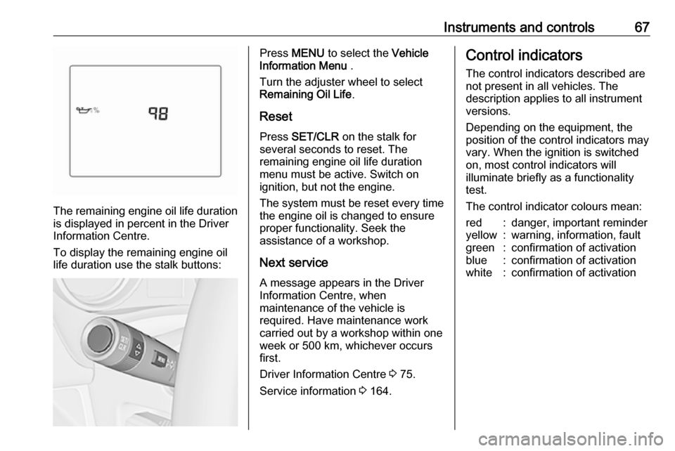
The remaining engine oil life duration
is displayed in percent in the Driver
Information Centre.
To display the remaining engine oil
life duration use the stalk buttons:
Press MENU to select the Vehicle
Information Menu .
Turn the adjuster wheel to select
Remaining Oil Life .
Reset Press SET/CLR on the stalk for
several seconds to reset. The
remaining engine oil life duration
menu must be active. Switch on
ignition, but not the engine.
The system must be reset every time
the engine oil is changed to ensure
proper functionality. Seek the
assistance of a workshop.
Next service A message appears in the Driver
Information Centre, when
maintenance of the vehicle is
required. Have maintenance work
carried out by a workshop within one
week or 500 km, whichever occurs first.
Driver Information Centre 3 75.
Service information 3 164.Control indicators
The control indicators described are
not present in all vehicles. The
description applies to all instrument
versions.
Depending on the equipment, the
position of the control indicators may vary. When the ignition is switched
on, most control indicators will
illuminate briefly as a functionality
test.
The control indicator colours mean:red:danger, important reminderyellow:warning, information, faultgreen:confirmation of activationblue:confirmation of activationwhite:confirmation of activation
Page 80 of 191
78Instruments and controlsDisplay of average consumption. Themeasurement can be reset at any
time and starts with a default value.
To reset, press SET/CLR for a few
seconds while viewing this page.
Timer
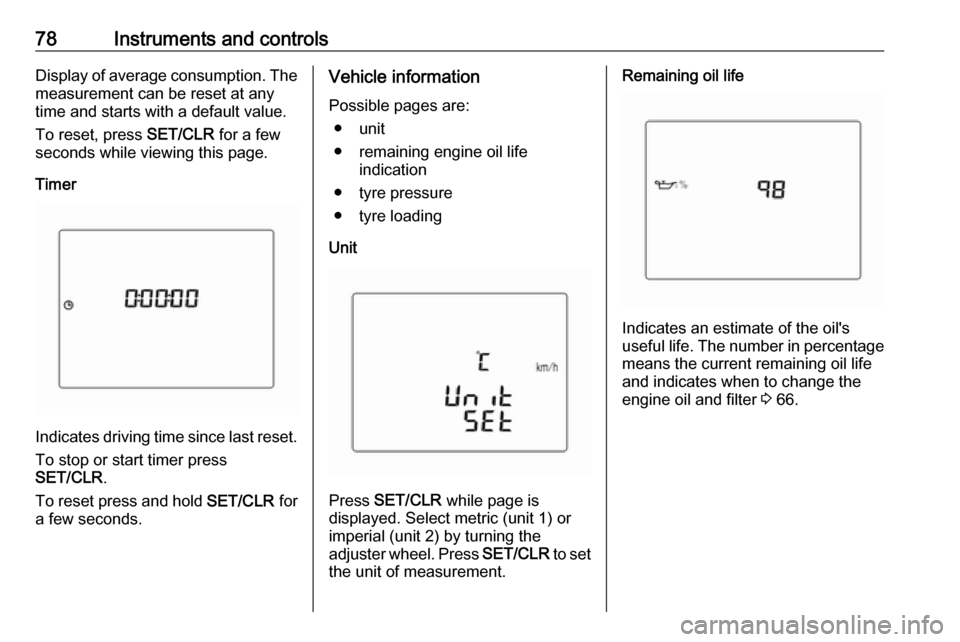
Indicates driving time since last reset.
To stop or start timer press
SET/CLR .
To reset press and hold SET/CLR for
a few seconds.
Vehicle information
Possible pages are: ● unit
● remaining engine oil life indication
● tyre pressure
● tyre loading
Unit
Press SET/CLR while page is
displayed. Select metric (unit 1) or
imperial (unit 2) by turning the
adjuster wheel. Press SET/CLR to set
the unit of measurement.
Remaining oil life
Indicates an estimate of the oil's
useful life. The number in percentage means the current remaining oil life
and indicates when to change the
engine oil and filter 3 66.
Page 84 of 191

82Instruments and controlsNo.Vehicle message15Centre high-mounted brake
light failure16Brake light failure17Headlight levelling malfunction18Left low beam failure19Rear fog light failure20Right low beam failure21Left sidelight failure22Right sidelight failure23Reversing light failure24Number plate light failure25Left front turn light failure26Left rear turn light failure27Right front turn light failure28Right rear turn light failure35Replace battery in radio remote
control36ESC InitialisingNo.Vehicle message49Lane departure warning unavailable52Change timing belt56Tyre pressure imbalance on
front axle57Tyre pressure imbalance on
rear axle59Open, then close driver window60Open, then close front
passenger window61Open, then close left rear
window62Open, then close right rear
window65Theft attempted66Service anti-theft alarm system67Service steering wheel lock68Service power steering75Service air conditioningNo.Vehicle message77Service lane departure warning79Top up engine oil81Service transmission / trans‐
mission malfunction82Change engine oil soon84Engine power reduced89Service vehicle soon90Service brake assist95Service airbag145Check washer fluid level151Press clutch to start174Low vehicle battery258Parking assist off
Vehicle messages on
Colour Info Display
Some important messages appear
additionally in the
Colour Info Display. Some messages only pop-up for a few seconds.
Page 121 of 191
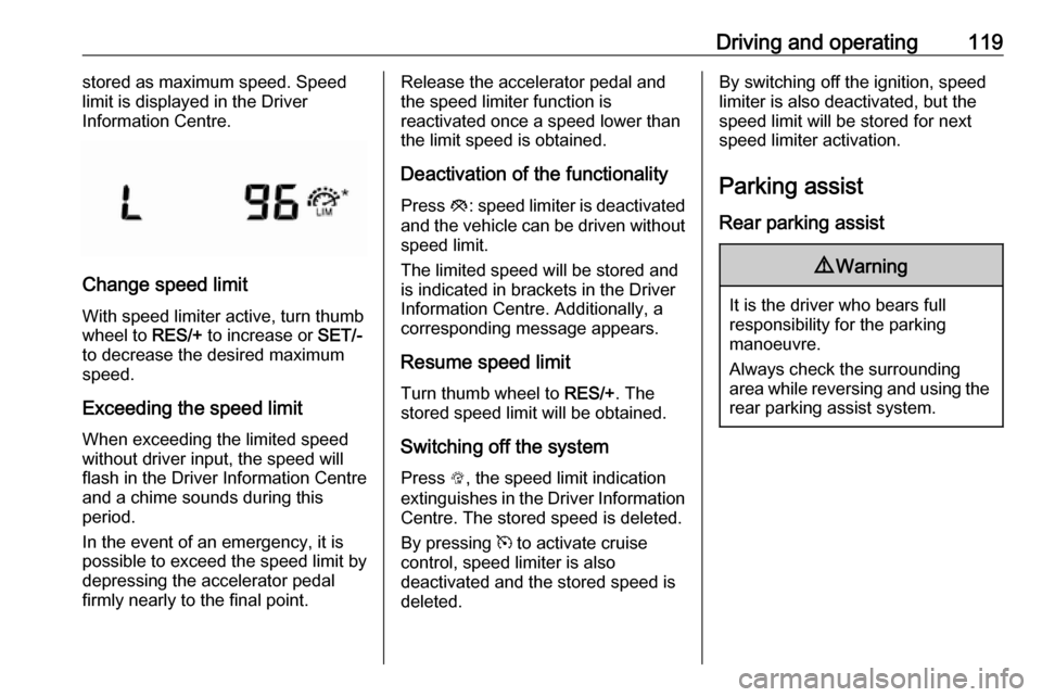
Driving and operating119stored as maximum speed. Speedlimit is displayed in the Driver
Information Centre.
Change speed limit
With speed limiter active, turn thumb
wheel to RES/+ to increase or SET/-
to decrease the desired maximum
speed.
Exceeding the speed limit
When exceeding the limited speed
without driver input, the speed will
flash in the Driver Information Centre
and a chime sounds during this
period.
In the event of an emergency, it is
possible to exceed the speed limit by
depressing the accelerator pedal
firmly nearly to the final point.
Release the accelerator pedal and
the speed limiter function is
reactivated once a speed lower than
the limit speed is obtained.
Deactivation of the functionality
Press y: speed limiter is deactivated
and the vehicle can be driven without
speed limit.
The limited speed will be stored and
is indicated in brackets in the Driver
Information Centre. Additionally, a
corresponding message appears.
Resume speed limit Turn thumb wheel to RES/+. The
stored speed limit will be obtained.
Switching off the system
Press L, the speed limit indication
extinguishes in the Driver Information Centre. The stored speed is deleted.
By pressing m to activate cruise
control, speed limiter is also
deactivated and the stored speed is
deleted.By switching off the ignition, speed
limiter is also deactivated, but the
speed limit will be stored for next
speed limiter activation.
Parking assist
Rear parking assist9 Warning
It is the driver who bears full
responsibility for the parking
manoeuvre.
Always check the surrounding
area while reversing and using the rear parking assist system.
Page 128 of 191

126Vehicle careVehicle careGeneral Information...................126
Accessories and vehicle modifications .......................... 126
Vehicle storage ........................127
End-of-life vehicle recovery .....127
Vehicle checks ........................... 128
Performing work ......................128
Bonnet ..................................... 128
Engine oil ................................. 129
Engine coolant ......................... 130
Washer fluid ............................ 131
Brakes ..................................... 131
Brake fluid ............................... 131
Vehicle battery ......................... 131
Wiper blade replacement ........133
Bulb replacement .......................134
Halogen headlights ..................134
Front fog lights ......................... 136
Front turn lights .......................136
Tail lights ................................. 137
Side turn lights ......................... 138
Centre high-mounted brake light ......................................... 138
Number plate light ...................139Interior lights ............................ 139
Instrument panel illumination ...139
Electrical system ........................140
Fuses ....................................... 140
Engine compartment fuse box . 141
Instrument panel fuse box .......143
Vehicle tools .............................. 144
Tools ........................................ 144
Wheels and tyres .......................145
Winter tyres ............................. 145
Tyre designations ....................145
Tyre pressure .......................... 146
Tyre pressure monitoring
system .................................... 147
Tread depth ............................. 150
Changing tyre and wheel size . 150 Wheel covers ........................... 150
Tyre chains .............................. 151
Tyre repair kit .......................... 151
Wheel changing .......................154
Spare wheel ............................ 155
Jump starting ............................. 159
Towing ....................................... 160
Towing the vehicle ...................160
Appearance care .......................161
Exterior care ............................ 161
Interior care ............................. 163General Information
Accessories and vehiclemodifications
We recommend the use of genuine
parts and accessories and factory approved parts specific for your
vehicle type. We cannot assess or
guarantee reliability of other products
- even if they have a regulatory or
otherwise granted approval.
Any modification, conversion or other changes made to standard vehicle
specifications (including, without
limitation, software modifications,
modifications of the electronic control
units) may invalidate the warranty
offered by Opel. Furthermore, such
changes may affect driver assistance
systems, fuel consumption, CO 2
emissions and other emissions of the
vehicle. They may also invalidate the
vehicle operating permit.
Page 138 of 191
136Vehicle care3. Detach bulb from the bulb holderand replace it.
4. Insert the bulb socket into the reflector and turn clockwise.
Sidelight / daytime running light
with LEDs
Sidelights and daytime running lights
are designed as LEDs and cannot be
changed. Consult a workshop in case
of a defective LED.
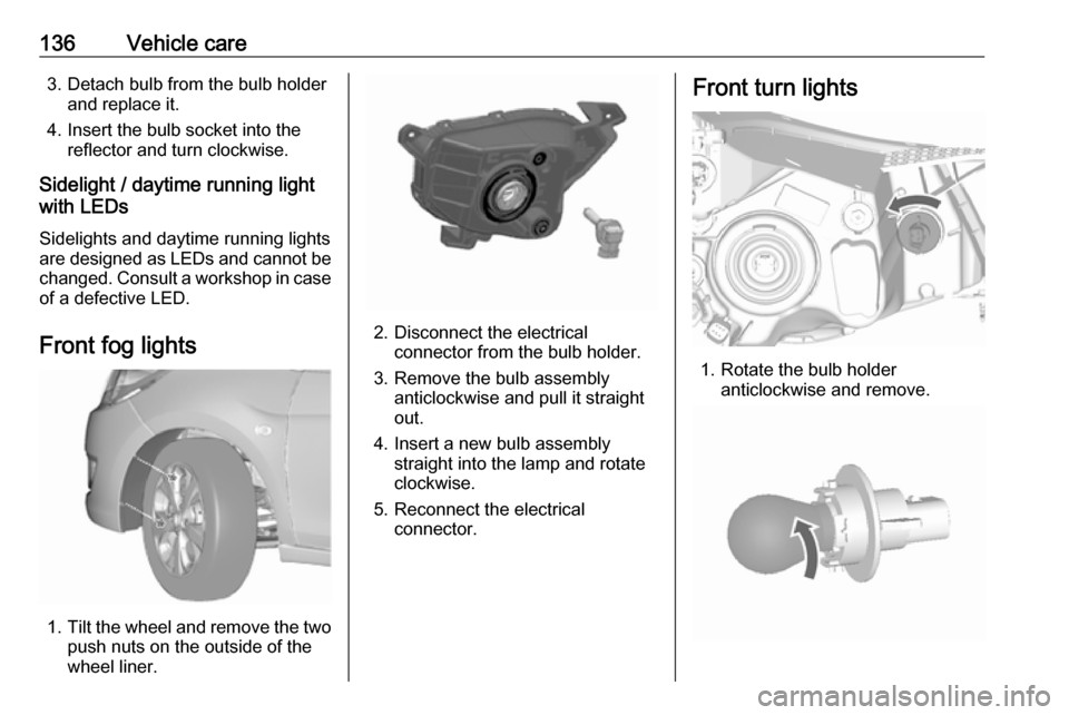
Front fog lights
1. Tilt the wheel and remove the two
push nuts on the outside of the
wheel liner.
2. Disconnect the electrical connector from the bulb holder.
3. Remove the bulb assembly anticlockwise and pull it straight
out.
4. Insert a new bulb assembly straight into the lamp and rotate
clockwise.
5. Reconnect the electrical connector.
Front turn lights
1. Rotate the bulb holderanticlockwise and remove.
Page 158 of 191
156Vehicle careOnly mount one temporary spare
wheel. The permissible maximum
speed on the label on the temporary
spare wheel is only valid for the
factory-fitted tyre size.
Fitting the spare wheel Make the following preparations and
observe the following information:
● Park the vehicle on a level, firm and non-skid surface. The front
wheels must be in the straight-
ahead position.
● Apply the parking brake and engage first gear or reverse gear.
● Remove the spare wheel 3 155.
● Never change more than one wheel at once.
● Use the jack only to change wheels in case of puncture, not
for seasonal winter or summer
tyre change.
● The jack is maintenance-free.
● If the ground on which the vehicle
is standing is soft, a solid board
(max. 1 cm thick) should be
placed under the jack.● Take heavy objects out of the vehicle before jacking up.
● No people or animals may be in the vehicle when it is jacked-up.
● Never crawl under a jacked-up vehicle.
● Do not start the vehicle when it is
raised on the jack.
● Clean wheel nuts and thread with
a clean cloth before mounting the wheel.9 Warning
Do not grease wheel bolt, wheel
nut and wheel nut cone.
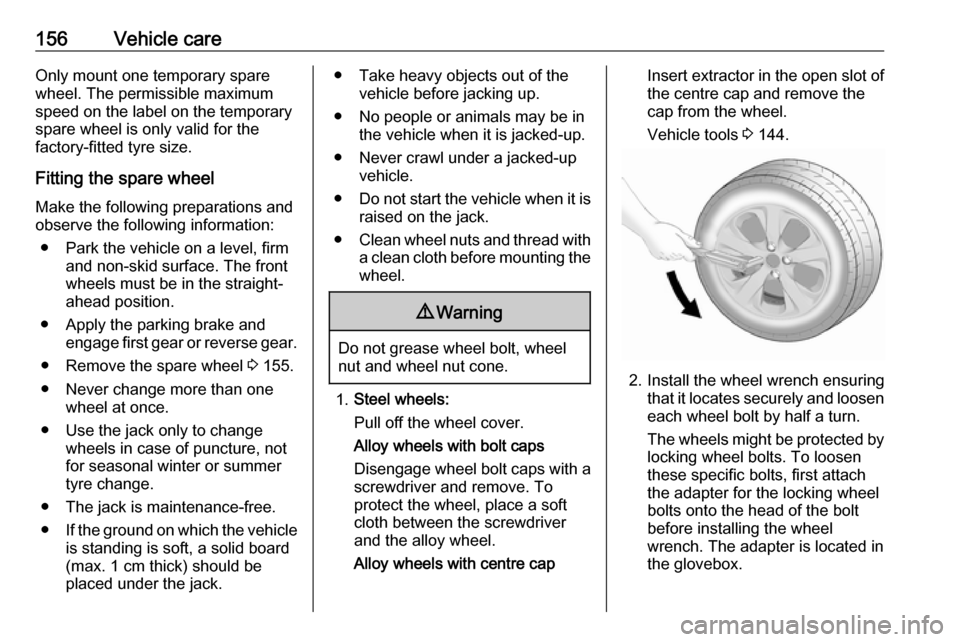
1. Steel wheels:
Pull off the wheel cover.
Alloy wheels with bolt caps
Disengage wheel bolt caps with a
screwdriver and remove. To
protect the wheel, place a soft
cloth between the screwdriver
and the alloy wheel.
Alloy wheels with centre cap
Insert extractor in the open slot of
the centre cap and remove the
cap from the wheel.
Vehicle tools 3 144.
2. Install the wheel wrench ensuring
that it locates securely and loosen
each wheel bolt by half a turn.
The wheels might be protected by
locking wheel bolts. To loosen
these specific bolts, first attach
the adapter for the locking wheel
bolts onto the head of the bolt
before installing the wheel
wrench. The adapter is located in
the glovebox.