oil level OPEL MANTA 1973 Service Manual
[x] Cancel search | Manufacturer: OPEL, Model Year: 1973, Model line: MANTA, Model: OPEL MANTA 1973Pages: 625, PDF Size: 17.22 MB
Page 16 of 625
LUBRICATION AND MAINTENANCE OC-7SERVICESLUBE AND GENERAL MAINTENANCE
Vehicle operation under conditions such as heavy
dust, continuous short trips, use of other than un-
leaded or low lead fuels or pulling trailers, is not
considered normal use and therefore more frequent
maintenance will be required. Such additional
maintenance requirements are included where appli-
cable.
Engine OilChange each 4 months or
3,COO miles, whichever
occurs first, or each 2 months or
3,ooO miles when
the vehicle is operated under the following condi-
tions: (a) driving in dusty conditions, (b) trailer pull-
ing, (c) extensive idling or (d) short-trip operation at
freezing temperatures (with engine not thoroughly
warmed-up).Engine oils have a definite effect on ease of starting,
oil economy, combustion chamber deposits and en-
gine wear. It is recommended that a” oil which,
according to the label on the can is; (1) intended for
service SE and (2) passes car makers’ tests be used.
Oils confotming to these types contain detergent ad-
ditives. -
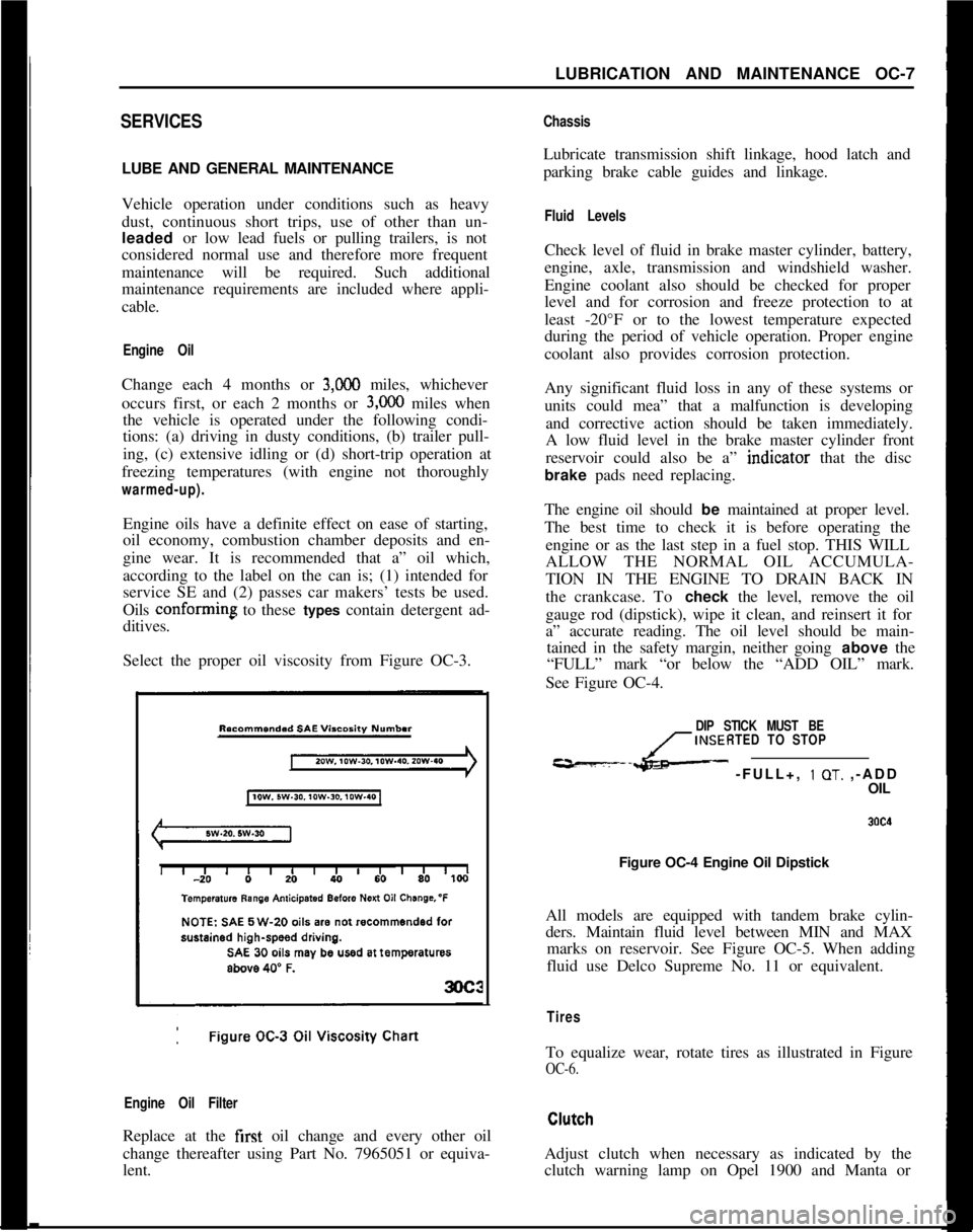
Select the proper oil viscosity from Figure OC-3.
Engine Oil FilterReplace at the first oil change and every other oil
change thereafter using Part No. 7965051 or equiva-
lent.
ChassisLubricate transmission shift linkage, hood latch and
parking brake cable guides and linkage.
Fluid LevelsCheck level of fluid in brake master cylinder, battery,
engine, axle, transmission and windshield washer.
Engine coolant also should be checked for proper
level and for corrosion and freeze protection to at
least -20°F or to the lowest temperature expected
during the period of vehicle operation. Proper engine
coolant also provides corrosion protection.
Any significant fluid loss in any of these systems or
units could mea” that a malfunction is developing
and corrective action should be taken immediately.
A low fluid level in the brake master cylinder front
reservoir could also be a” indtcator that the disc
brake pads need replacing.
The engine oil should be maintained at proper level.
The best time to check it is before operating the
engine or as the last step in a fuel stop. THIS WILL
ALLOW THE NORMAL OIL ACCUMULA-
TION IN THE ENGINE TO DRAIN BACK IN
the crankcase. To check the level, remove the oil
gauge rod (dipstick), wipe it clean, and reinsert it for
a” accurate reading. The oil level should be main-
tained in the safety margin, neither going above the
“FULL” mark “or below the “ADD OIL” mark.
See Figure OC-4.
DIP STICK MUST BE
INSERTED TO STOP
---L- -FULL+, 1 OT. ,-ADD
OIL
Figure OC-4 Engine Oil Dipstick
All models are equipped with tandem brake cylin-
ders. Maintain fluid level between MIN and MAX
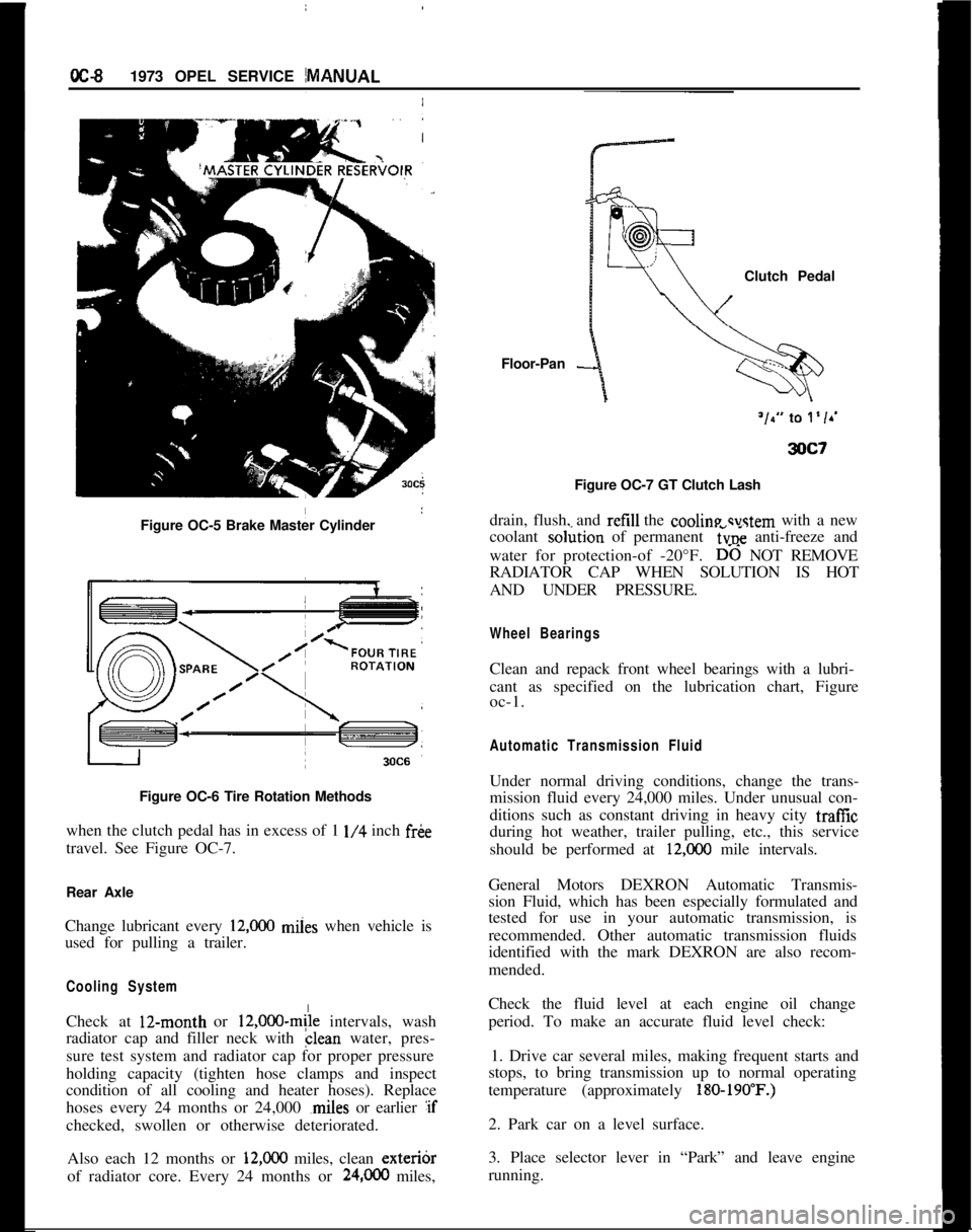
marks on reservoir. See Figure OC-5. When adding
fluid use Delco Supreme No. 11 or equivalent.
TiresTo equalize wear, rotate tires as illustrated in Figure
OC-6.Adjust clutch when necessary as indicated by the
clutch warning lamp on Opel 1900 and Manta or
Page 17 of 625
IoC-91973 OPEL SERVICE MANUAL
Figure OC-5 Brake Master Cylinder
I
Figure OC-6 Tire Rotation Methods
when the clutch pedal has in excess of 1
l/4 inch fr&
travel. See Figure OC-7.
Rear Axle
Change lubricant every
12,ooO miies when vehicle is
used for pulling a trailer.
Cooling SystemCheck at 12-month or
12,000~mile intervals, wash
radiator cap and filler neck with clean water, pres-
sure test system and radiator cap for proper pressure
holding capacity (tighten hose clamps and inspect
condition of all cooling and heater hoses). Replace
hoses every 24 months or 24,000 ,miles or earlier :if
checked, swollen or otherwise deteriorated.
Also each 12 months or
12,ooO miles, clean exteribr
of radiator core. Every 24 months or
24,OCO miles,Floor-Pan
-Clutch Pedal
Figure OC-7 GT Clutch Lash
drain, flush, and refill the cooline svstem with a new
coolant so&ion of permanent
6~; anti-freeze and
water for protection-of -20°F.
D-6 NOT REMOVE
RADIATOR CAP WHEN SOLUTION IS HOT
AND UNDER PRESSURE.
Wheel BearingsClean and repack front wheel bearings with a lubri-
cant as specified on the lubrication chart, Figure
oc-1.
Automatic Transmission FluidUnder normal driving conditions, change the trans-
mission fluid every 24,000 miles. Under unusual con-
ditions such as constant driving in heavy city traffic
during hot weather, trailer pulling, etc., this service
should be performed at
12,COO mile intervals.
General Motors DEXRON Automatic Transmis-
sion Fluid, which has been especially formulated and
tested for use in your automatic transmission, is
recommended. Other automatic transmission fluids
identified with the mark DEXRON are also recom-
mended.
Check the fluid level at each engine oil change
period. To make an accurate fluid level check:
1. Drive car several miles, making frequent starts and
stops, to bring transmission up to normal operating
temperature (approximately
180-190’F.)2. Park car on a level surface.
3. Place selector lever in “Park” and leave engine
running.
Page 19 of 625
CC-10 1973 OPEL SERVICE MANUAL
wiper blades. Check amount and direction of fluid
sprayed by washers during use.,
E. Defrosters - Check performance by moving con-
trols to “DEF” and noting
am$nmt of air directed
against the windshield.
I
F. Wheel Alignment and
Balabce - In addition to
abnormal tire wear, the need fbr wheel alignment
service may be indicated by a pull to the right or
!eftwhen driving on a straight and level road. The need
for wheel balancing is usually
iddicated by a vibra-
tion of the steering wheel or
se;+ tihile driving at
normal highway speeds.I
IG. Brakes
- Be alert to illumiriation of the brake
warning light or changes in braking action,
SUCK as
repeated pulling to one side, unusual sounds when
braking or increased brake pedal travel. Any of thesecould indicate the need for
brakk system inspection
and/or service.
H. Parking Brake and Transmission “PARK”
Mechanism
- Check parking brake holding ability by
parking on a fairly steep hill and restraining the vehi-
cle with the parking brake only.
eon cars with auto-
matic transmissions, check the holding ability of the
“PARK” mechanism by releasing all brakes after
the transmission selector lever hak been placed in the“P” position.
I. Glass
- Check for broken, scrritched, dirty or da-
maged glass on vehicle that
coulld obscure vision’or
become an injury hazard.
J. Lights and Buzzers
- Check all instrument panel
illuminating and warning lights,’ seat belt reminder
light and buzzer, ignition key
b&er, interior lights,
license plate lights, side marker! lights, headlamps,
parking lamps, tail lamps, brake lights, turn signals,
backup lamps, and hazard warding flashers. Have
someone observe operation of
&ach exterior light
while you activate the controls: The operation of
instrument panel warning lights is covered in the
“Starting and Operating“ section of your
Own&%
Manual.K. Transmission Shift Indicator
‘- Check to be sure
automatic transmission shift
indiCator accurately i”-
dicates the shift position selected.
I
CAUTION: Before making thk check below,I
be sure to have a clear dist&e ahead and:
behind the car, set the parking brake and
firmly apply the foot brake.
Do not depress
accelerator pedal. Be prepared to
turn off ’
ignition switch
immediat+y if engine
should start.L. Starter Safety Switch (Automatic Transmissibn
Cars)
- Check starter safety switch by placing the
transmission in each of the driving gears while
at-tempting to start the engine. The starter should oper-ate only in the Park (“P”) or Neutral (“N”)
positions.
M. Horn
- Blow the horn occasionally to be sure thatit works. (Ignition switch must be in the “ON” posi-
tion.)
N. Seat Back Latches
- Check to see that seat back
latches are holding by pulling forward on the top of
each folding seat back.
0. Rearview Mirrors and Sun Visors
- Check that
friction joints are properly adjusted so mirrors and
sun visors stay in the selected position.
P. Door Latches
- Check for positive closing, latch-
ing and locking.
Q. Hood Latches - Check to make sure hood closesfirmly by pressing on the hood at the latching point
after each closing. Check also for broken, damaged
or missing parts which might prevent secure latch-
ing.R. Fluid Leaks
- Check for fuel, water, oil or other
fluid leaks by observing the ground beneath the vehi-cle after it has been parked for a while. If gasoline
fumes or fluid are noticed at any time, the cause
should be determined and corrected without delay
because of the possibility of fire.
S. Exhaust System
- Be alert to any change in the
sound of the exhaust system or a smell of fumes
which may indicate a leak.
Head Restraints
- Check that no head restraint
components are missing, damaged or loose. (Does
not apply to GT Models).
Disc BrakesCheck brake pads and condition of rotors while
wheels are removed during tire rotation. (Note belowregarding more frequent checks also applies to disc
brakes.)
Parking and Drum BrakesCheck drum
brake linings and other internal brake
components at each wheel (drums, wheel cylinders,
etc.). Parking brake adjustment also should be
checked whenever drum brake linings are checked.
NOTE: More frequent checks should be
made if driving conditions a.nd habits result
in frequent brake application. When brakes
require relining, it is recommended thatyou use those genuine General Motors
parts specified for your car,and Delco fluid
as required.
Page 274 of 625
DISC BRAKES5B- 15
ConditionPossible Cause
2. Binding brake pedal
mechanism.Correction
2. Check and lubricate, ifnecessary.3. Corroded caliper
assembly.3. Clean and lubricate.
MAINTENANCE AND ADJUSTMENTSDISC BRAKE MAINTENANCE
Checking Brake Fluid Level
The brake fluid level in the brake fluid container
must be checked during predelivery inspection, then
every 3,000 miles during inspection and preventive
maintenance servicing.
The brake fluid level must not be higher than the
inscription “MAX” and must be at least up to
“MIN”. Replenish brake fluid, if necessary.
Because of the relatively large brake caliper bore
cross section and the self-adjustment of the disc
brakes, resulting in a greater piston travel to compen-
sate for friction pad wear, the brake fluid level drops
faster than in fluid containers for drum brakes with
their smaller wheel brake cylinders. For this reason
pay special attention to the fluid level in the brake
fluid container.
Drop of brake fluid level can be due to friction pad
wear and may not be due to leakage in the braking
system.On loss of brake fluid due to leakage, the brake sys-
tem must be checked thoroughly.
Friction Pad Adjustment
Friction pad adjustment is not necessary on the front
wheel disc brakes as this is done automatically by the
pistons in the brake calipers.
Lubricating Front Wheel Bearings
When removing one or both brake discs, check lu-
brication of front wheel bearings and the cavity of
the wheel hub and replenish if necessary (see operat-
ion
“Removing and Reinstalling Brake Disc”).
When carrying out other work on disc brakes which
does not necessitate the removal and installation of
the brake disc, lubricating wheel bearings is not
necessary.Checking Disc Brake Friction Pads for Wear
Whenever a disc brake equipped car is in for periodic
service, while the car is raised, the friction pads in
both brake calipers should be checked for wear by
making a simple measurement. Worn or oily friction
pads must be replaced.
Measure friction pad wear as follows:
1. Remove friction pads.
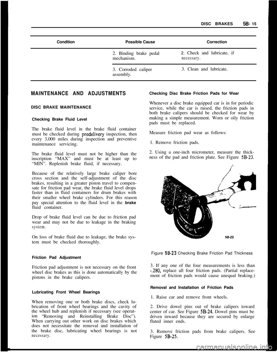
2. Using a one-inch micrometer, measure the thick-
ness of the pad and friction plate. See Figure
5B-23.Figure 58-23 Checking Brake Friction Pad Thickness
3. If any one of the four measurements is less than
-.280, replace all four friction pads. (Partial replace-
ment of friction pads would cause unequal braking.)
Removal and Installation of Friction Pads
1. Raise car and remove front wheels.
2. Drive dowel pins out of brake calipers toward
center of car. See Figure
5B-24. Dowel pins must be
driven inward because they are secured by enlarge
fluted inner ends.
3. Remove friction pads from brake calipers. See
Figure
5B-25.
Page 287 of 625
5C- 281973 OPEL SERVICE MANUAL
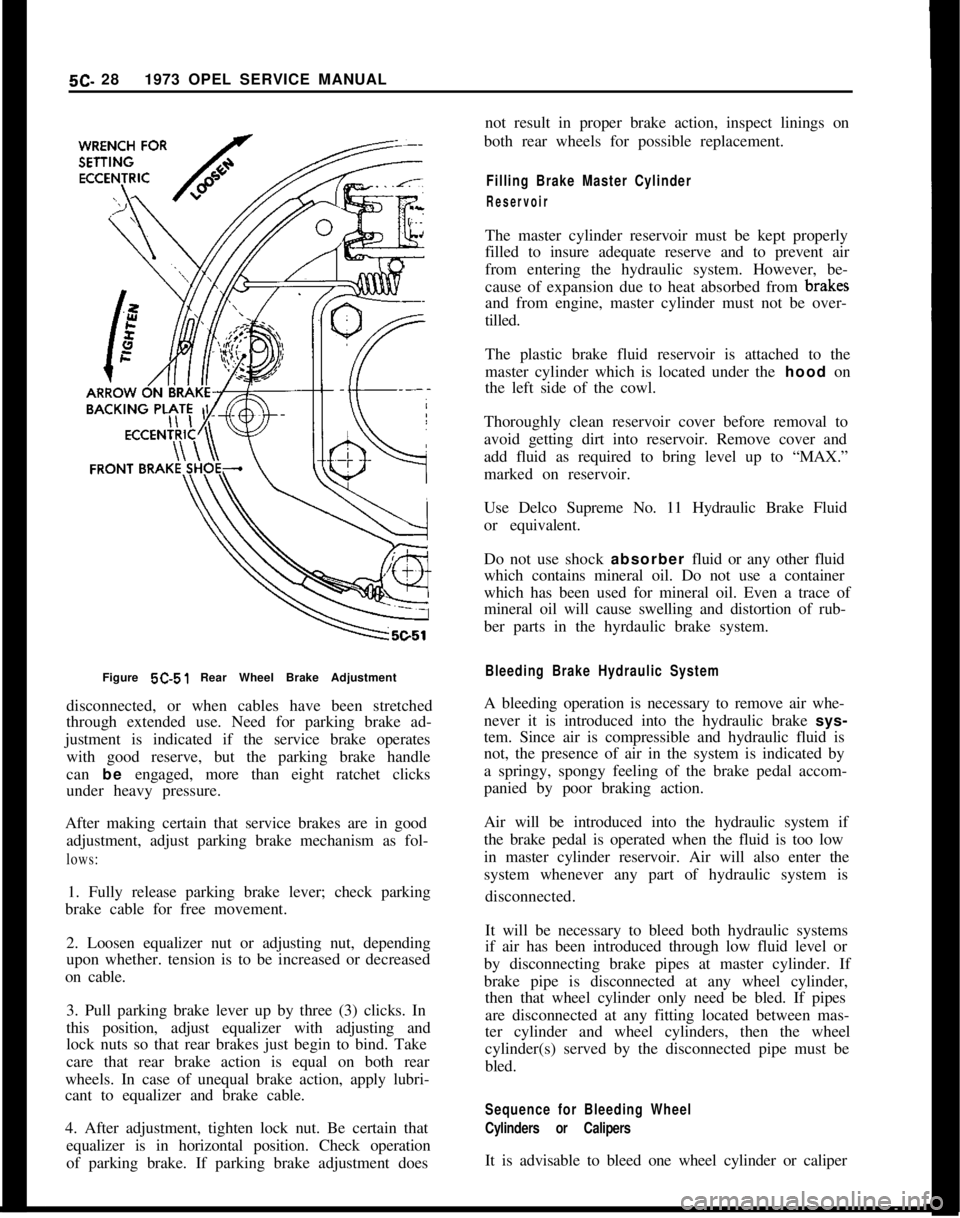
Figure 5C-51 Rear Wheel Brake Adjustment
disconnected, or when cables have been stretched
through extended use. Need for parking brake ad-
justment is indicated if the service brake operates
with good reserve, but the parking brake handle
can be engaged, more than eight ratchet clicks
under heavy pressure.
After making certain that service brakes are in good
adjustment, adjust parking brake mechanism as fol-lows:1. Fully release parking brake lever; check parking
brake cable for free movement.
2. Loosen equalizer nut or adjusting nut, depending
upon whether. tension is to be increased or decreased
on cable.
3. Pull parking brake lever up by three (3) clicks. In
this position, adjust equalizer with adjusting and
lock nuts so that rear brakes just begin to bind. Take
care that rear brake action is equal on both rear
wheels. In case of unequal brake action, apply lubri-
cant to equalizer and brake cable.
4. After adjustment, tighten lock nut. Be certain that
equalizer is in horizontal position. Check operation
of parking brake. If parking brake adjustment doesnot result in proper brake action, inspect linings on
both rear wheels for possible replacement.
Filling Brake Master Cylinder
ReservoirThe master cylinder reservoir must be kept properly
filled to insure adequate reserve and to prevent air
from entering the hydraulic system. However, be-
cause of expansion due to heat absorbed from brakff
and from engine, master cylinder must not be over-
tilled.
The plastic brake fluid reservoir is attached to the
master cylinder which is located under the hood on
the left side of the cowl.
Thoroughly clean reservoir cover before removal to
avoid getting dirt into reservoir. Remove cover and
add fluid as required to bring level up to “MAX.”
marked on reservoir.
Use Delco Supreme No. 11 Hydraulic Brake Fluid
or equivalent.
Do not use shock absorber fluid or any other fluid
which contains mineral oil. Do not use a container
which has been used for mineral oil. Even a trace of
mineral oil will cause swelling and distortion of rub-
ber parts in the hyrdaulic brake system.
Bleeding Brake Hydraulic SystemA bleeding operation is necessary to remove air whe-
never it is introduced into the hydraulic brake sys-
tem. Since air is compressible and hydraulic fluid is
not, the presence of air in the system is indicated by
a springy, spongy feeling of the brake pedal accom-
panied by poor braking action.
Air will be introduced into the hydraulic system if
the brake pedal is operated when the fluid is too low
in master cylinder reservoir. Air will also enter the
system whenever any part of hydraulic system is
disconnected.
It will be necessary to bleed both hydraulic systems
if air has been introduced through low fluid level or
by disconnecting brake pipes at master cylinder. If
brake pipe is disconnected at any wheel cylinder,
then that wheel cylinder only need be bled. If pipes
are disconnected at any fitting located between mas-
ter cylinder and wheel cylinders, then the wheel
cylinder(s) served by the disconnected pipe must be
bled.
Sequence for Bleeding Wheel
Cylinders or CalipersIt is advisable to bleed one wheel cylinder or caliper
Page 288 of 625
DRUM BRAKESBC- 29
at a time to avoid getting fluid level in reservoir
dangerously low. The correct sequence for bleeding
is bleed the wheel cylinder or caliper nearest the
master cylinder first in either circuit.
Do not perform bleeding operation while any brake
drum is removed.
Bleeding Wheel Cylinder or Caliper
1. Check fluid level, in reservoir and refill, if neces-
sary. Level must be brought up to “MAX” mark on
plastic reservoir.
2. Clean all dirt from around respective bleeder
valve, and then remove cap.
3. Push bleeder hose over bleeder valve, placing
other end of hose in a glass jar. Bleeder hose should
always be used to avoid getting fluid on linings.
4. Hold pressure on brake pedal and crack open the
bleeder valve to allow air (and,or) brake fluid to flow
out of the system. Allow pedal to travel to the floor.
Close bleeder valve. Release pedal and repeat this
procedure at each wheel cylinder in the circuit until
all air is removed. Frequently check reservoir fluid
level. Allowing fluid to be emptied will draw air into
the system.
5. Remove bleeder hose and install cap.
6. When bleeding operation is completed, make sure
that fluid level is brought up to “MAX” marking on
reservoir, then install cover.
7. Discard the brake fluid deposited in glass jar dur-
ing bleeding operation.
Flushing Brake Hydraulic System
It is recommended that both brake system circuits be
thoroughly flushed whenever the master cylinder is
replaced or if there is any doubt as to the grade of
fluid in the system.
Flushing of the brake system is performed in the
same manner as the bleeding operation except that
fluid is forced through the lines and wheel cylinder
until it emerges clear in color. Approximately one
half pint of brake fluid is required to flush the hy-
draulic system thoroughly.
When flushing is completed, make certain the master
cylinder reservoir is filled to the proper level.Figure
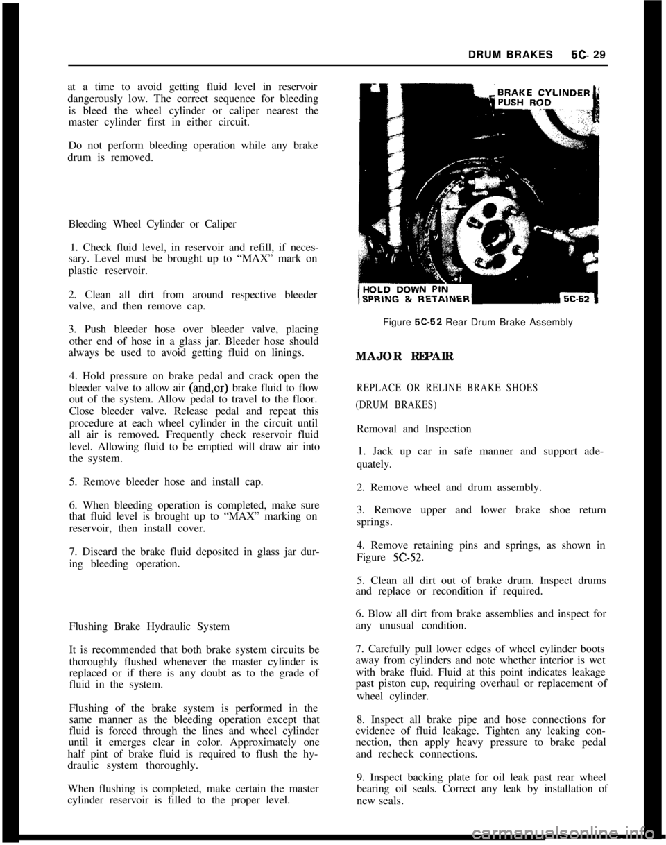
5C-52 Rear Drum Brake Assembly
MAJOR REPAIR
REPLACE OR RELINE BRAKE SHOES
(DRUM BRAKES)Removal and Inspection
1. Jack up car in safe manner and support ade-
quately.
2. Remove wheel and drum assembly.
3. Remove upper and lower brake shoe return
springs.
4. Remove retaining pins and springs, as shown in
Figure
5C-52.5. Clean all dirt out of brake drum. Inspect drums
and replace or recondition if required.
6. Blow all dirt from brake assemblies and inspect for
any unusual condition.
7. Carefully pull lower edges of wheel cylinder boots
away from cylinders and note whether interior is wet
with brake fluid. Fluid at this point indicates leakage
past piston cup, requiring overhaul or replacement of
wheel cylinder.
8. Inspect all brake pipe and hose connections for
evidence of fluid leakage. Tighten any leaking con-
nection, then apply heavy pressure to brake pedal
and recheck connections.
9. Inspect backing plate for oil leak past rear wheel
bearing oil seals. Correct any leak by installation of
new seals.
Page 289 of 625
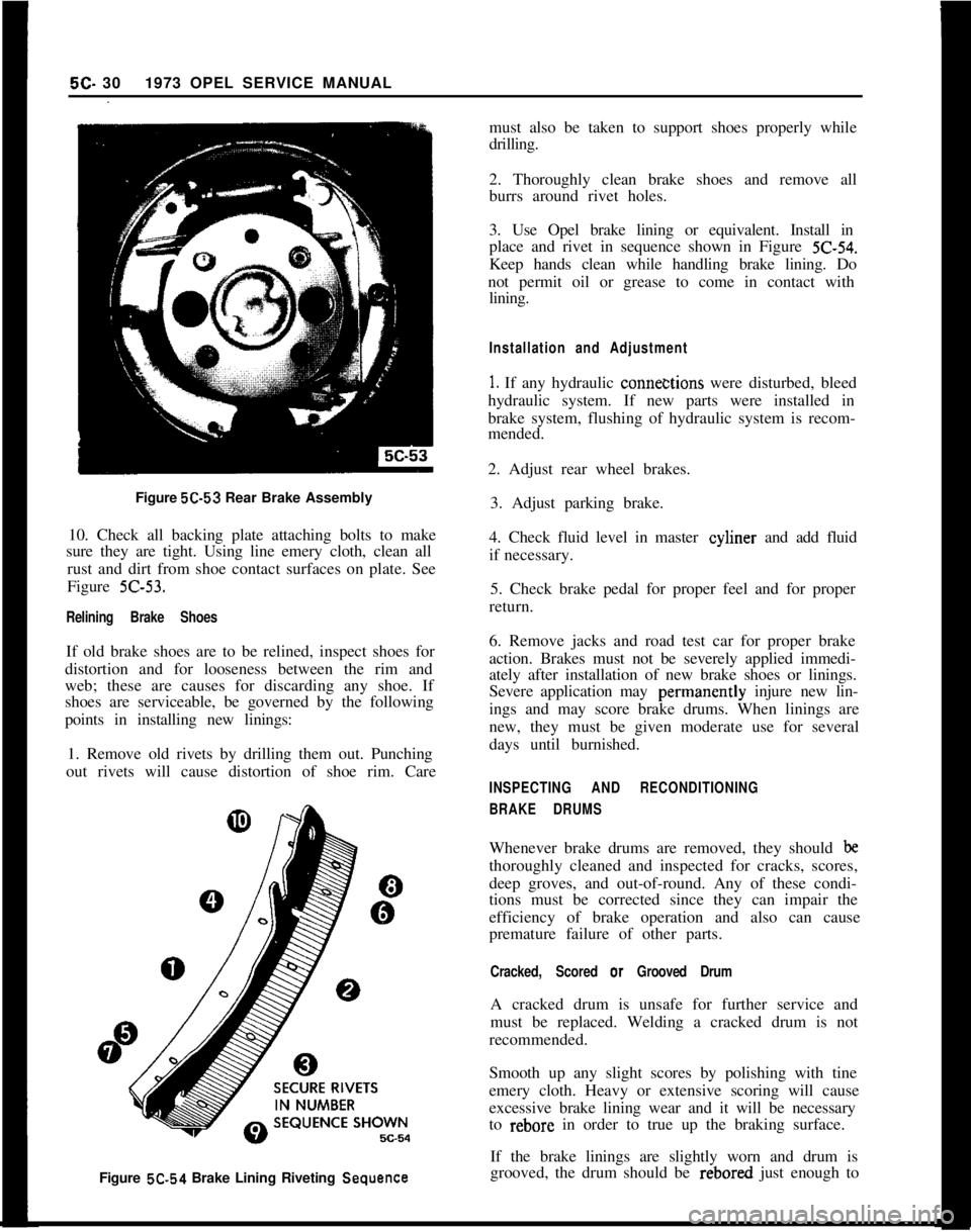
Figure 5C-53 Rear Brake Assembly
10. Check all backing plate attaching bolts to make
sure they are tight. Using line emery cloth, clean all
rust and dirt from shoe contact surfaces on plate. See
Figure Z-53.
Relining Brake ShoesIf old brake shoes are to be relined, inspect shoes for
distortion and for looseness between the rim and
web; these are causes for discarding any shoe. If
shoes are serviceable, be governed by the following
points in installing new linings:
1. Remove old rivets by drilling them out. Punching
out rivets will cause distortion of shoe rim. Care5C- 301973 OPEL SERVICE MANUAL
must also be taken to support shoes properly while
drilling.
2. Thoroughly clean brake shoes and remove all
burrs around rivet holes.
3. Use Opel brake lining or equivalent. Install in
place and rivet in sequence shown in Figure
Z-54.Keep hands clean while handling brake lining. Do
not permit oil or grease to come in contact with
lining.
Installation and Adjustment
1. If any hydraulic conne&tions were disturbed, bleed
hydraulic system. If new parts were installed in
brake system, flushing of hydraulic system is recom-
mended.
2. Adjust rear wheel brakes.
3. Adjust parking brake.
4. Check fluid level in master cyliner and add fluid
if necessary.
5. Check brake pedal for proper feel and for proper
return.
6. Remove jacks and road test car for proper brake
action. Brakes must not be severely applied immedi-
ately after installation of new brake shoes or linings.
Severe application may perinanently injure new lin-
ings and may score brake drums. When linings are
new, they must be given moderate use for several
days until burnished.
INSPECTING AND RECONDITIONING
BRAKE DRUMSWhenever brake drums are removed, they should
bethoroughly cleaned and inspected for cracks, scores,
deep groves, and out-of-round. Any of these condi-
tions must be corrected since they can impair the
efficiency of brake operation and also can cause
premature failure of other parts.
Cracked, Scored or Grooved DrumA cracked drum is unsafe for further service and
must be replaced. Welding a cracked drum is not
recommended.
Smooth up any slight scores by polishing with tine
emery cloth. Heavy or extensive scoring will cause
excessive brake lining wear and it will be necessary
to rebore in order to true up the braking surface.
Figure 5C.54 Brake Lining Riveting
SequenceIf the brake linings are slightly worn and drum is
grooved, the drum should be rebored just enough to
Page 297 of 625
6A. 61973 OPEL SERVICE MANUALDIAGNOSIS
EXCESSIVE OIL CONSUMPTION
ConditionCorrectionExternal Oil Leaks at:Tighten attaching bolts. If leaks
Rocker Arm Coverspersist, remove cover (or pan),
Crankcase Front Covercheck sealing surfaces for burrs
Oil Pan and Gasketor scoring, replace gasket, and
seal bolts with silastic sealer or
equivalent. Make sure oil level
,is not overfull.
Improper Reading of Dip-Car may not be level when taking r
StickInsuffIcient oil “drain-back” time
after stopping engine (three
minutes must be allowed). Dip-
stick may not be completely pushed
down against stop. Dipstick may
be bent.
Oil Viscosity Too LightUse recommended SAE viscosity for
prevailing temperatures.
Continuous High-SpeedAt speeds above 60 mph, increased
Drivingsumption can be expected with any
Inform customer of this fact.
High-Speed DrivingWhen principal use of automobile i
Following Normal Slowcity driving, crankcase dilution f
Speed City Drivingcondensation occurs. High speed a
temperatures will remove water,
resulting in what appears to be
rapid lowering of oil level.
Inform customer of this fact.
Piston Rings NotAllow engine to accumulate at leas
“Broken In”
4,OCO miles before attempting any
engine disassembly to correct for
oil consumption.
NOISY VALVES AND LIFTERSIf the preceding check indicates valve mechanism is
abnormally noisy, remove the rocker arm cover so
that the various conditions that cause noise may be
The noise level of the valve mechanism cannot bechecked. A piece of heater hose of convenient length
properly judged where the engine is below operatingmay be used to pick out the particular valves or valve
temperature when the hood is raised, or when thelinkages
thit are causing abnormal noise. With the
valve rocker arm covers are removed.engine running at a speed where the noise is pro-
nounced; hold the end of hose to an ear and hold
Before attempting to judge valve noise level, the en-other end about
l/2 inch from point of contact be-
gine must be thoroughly warmed up (at least 20tween rocker arm and valve stem. Mark or record the
minutes of operation at
1200 to 1500 RPM) to stabil-noisy valves for investigation of following causes:ize oil and coolant temperatures and bring all engine
parts to a normal state of expansion. When the
en-1. Sticking, Warped, or Eccentric Valves, Worngine is warmed up, listen for engine noise while
sit-Guides Sticking valves will cause irregular engine
ting in the driver’s seat with the hood closed. Run theoperation or missing on a low speed pull and will
engine at idle and at various higher speeds.usually cause intermittent noise.
Page 323 of 625
66.321973 OPEL SERVICE MANUAL
COOLING SYSTEM
CONTENTS
Subject
DESCRIPTION AND OPERATION:
Cooling System and Water Pump
. . . . . . . . . . . . . . . . . . . . . . . . . . . . . . . .DIAGNOSIS: (Not Applicable)
MAINTENANCE AND ADJUSTMENTS:
Checking and Filling Cooling System
. . . . . . . . . . . . . . . . . . . . . . . .Draining
andFlushingCoolingSystem. . . . . . . . . . . . . . . . . . . . . .Conditioning the Cooling System
. . . . . . . . . . . . . . . . . . . . . . . . . . . . . . . .Using and Testing Anti-Freeze Solutions
. . . . . . . . . . . . . . . . . .Fan Belt Adjustment or Replacement
. . . . . . . . . . . . . . . . . . . . . . . .Radiator Thermostat Inspection and Test
. . . . . . . . . . . . . . . .MAJOR REPAIR:
Water Pump Removal
. . . . . . . . . . . . . . . . . . . . . . . . . . . . . . . . . . . . . . . . . . . . . . . . . . . . .Radiator
Removal. . . . . . . . . . . . . . . . . . . . . . . . . . . . . . . . . . . . . . . . . . . . . . . . . . . . . . . . . . . . . .SPECIFICATIONS:
Cooling System Capacities
. . . . . . . . . . . . . . . . . . . . . . . . . . . . . . . . . . . . . . . . . . . .Page No.
68-32
6B-32
68-32
68-33
68-33
68-33
68-33
68-34
68-34
6B-35
DESCRIPTION AND OPERATION
COOLING SYSTEM AND WATER PUMPThe coiling system is of the conventional pressurized
type. A centrifugal pump arranged in timing case
serves to circulate the coolant.
When the thermostat is closed, the coolant will re-
turn to the pump via a by-pass for swift and uniform
warming up of the engine the coolant circulates
through the radiator, only when the engine has
reached normal operating temperature.
The heater system branches off the cooling system
ahead of thermostat in flow direction so that the
heater is in operation before engine has reached full
operating temperature.
MAINTENANCE AND ADJUSTMENTS
Checking and Filling Cooling SystemThe coolant level should be checked only when the
engine is cold and only enough coolant should be
added to bring the level halfway between core andtank top. It is unnecessary and undesirable to remove
the radiator cap and check the coolant level each
time the car stops at a filling station for gasoline or
oil, since the engine is usually hot at such times.
WARNING: Never remove the radiator cap quickly
when engine is HOT Sudden release of cooling
sys-
tern pressure may cause the coolant to boil and some
of it may be ejected from the radiator
filler neck,
resulting in
inl’ury to persons or damage to the car
finish.If it is necessary at any time to remove the radiator
cap when engine is hot, rotate the cap counterclock-
wise until first stop is reached. Leave cap in this
position until all pressure in cooling system has been
released, then turn cap past the first stop and remove
it.
Draining and Flushing
Cooling SystemThe cooling system should be completely drained
and the recommended coolant installed every two (2)
years.To drain the cooling system, remove radiator cap,
remove lower radiator hose from the lower tank and
Page 329 of 625
6C- 381973 OPEL SERVICE MANUALCAUTION:Because the fuel pump is below fuel tank
level, fuel
will drain from the tank. when the supply
hne is disconnected from the fuel pump.1. Pull fuel supply line and rubber connector from
fuel pump. Plug rubber connector to prevent fuel
loss.2. Remove fuel pump cap, gasket and plastic
strainer.
3. Cover center opening in sediment bowl with finger
and blow out sediment bowl with compressed air.
4. Wash plastic strainer in solvent; if strainer does
not clean-up or is damaged, replace strainer.
5. Install clean parts, noting the following:
(a) Strainer must be properly seated with projections
facing upward.(b) A new cap gasket must be positioned over
strainer.
(c) Sealing ring must be in place on cap retaining
screw.6. Reconnect fuel supply line. Start engine and check
for leaks.
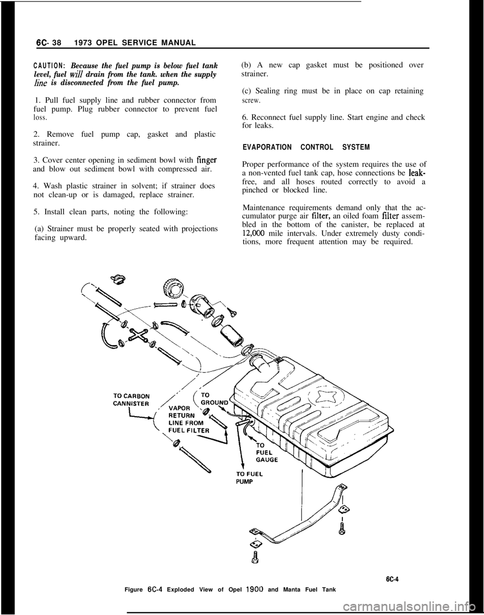
EVAPORATION CONTROL SYSTEMProper performance of the system requires the use of
a non-vented fuel tank cap, hose connections be leak-
free, and all hoses routed correctly to avoid a
pinched or blocked line.
Maintenance requirements demand only that the ac-
cumulator purge air tilter, an oiled foam filter assem-
bled in the bottom of the canister, be replaced at
12,CKO mile intervals. Under extremely dusty condi-
tions, more frequent attention may be required.
Figure
W-4 Exploded View of Opel 1900 and Manta Fuel Tank