ECU OPEL MOVANO_B 2017 Owner's Guide
[x] Cancel search | Manufacturer: OPEL, Model Year: 2017, Model line: MOVANO_B, Model: OPEL MOVANO_B 2017Pages: 255, PDF Size: 6.12 MB
Page 175 of 255
Vehicle care173Caution
Do not allow the engine oil level todrop below the minimum level!
We recommend the use of the same
type of engine oil that was used at the
last change.
The engine oil level must not exceed the maximum mark MAX on the
dipstick.
Caution
Overfilled engine oil must be
drained or suctioned out.
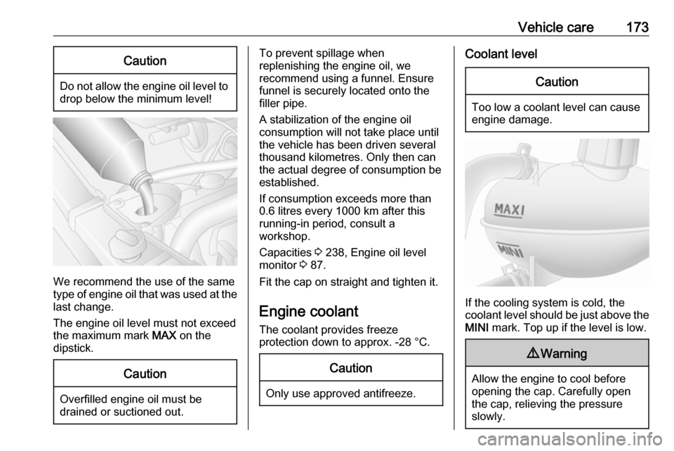
To prevent spillage when
replenishing the engine oil, we
recommend using a funnel. Ensure funnel is securely located onto the
filler pipe.
A stabilization of the engine oil
consumption will not take place until
the vehicle has been driven several
thousand kilometres. Only then can
the actual degree of consumption be
established.
If consumption exceeds more than
0.6 litres every 1000 km after this
running-in period, consult a
workshop.
Capacities 3 238, Engine oil level
monitor 3 87.
Fit the cap on straight and tighten it.
Engine coolant The coolant provides freeze
protection down to approx. -28 °C.Caution
Only use approved antifreeze.
Coolant levelCaution
Too low a coolant level can cause engine damage.
If the cooling system is cold, the
coolant level should be just above the
MINI mark. Top up if the level is low.
9Warning
Allow the engine to cool before
opening the cap. Carefully open
the cap, relieving the pressure
slowly.
Page 182 of 255
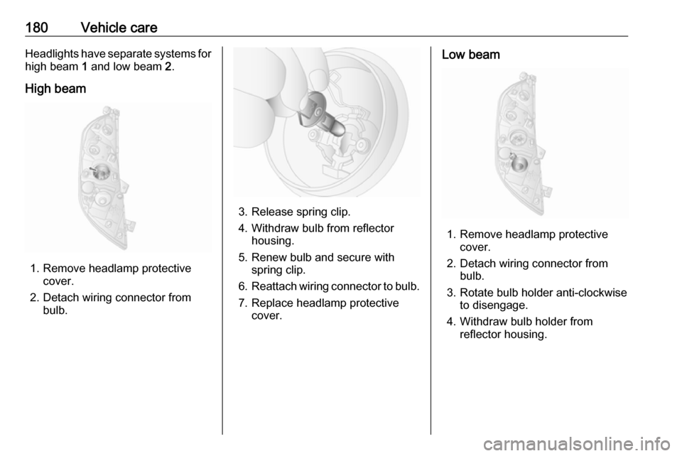
180Vehicle careHeadlights have separate systems forhigh beam 1 and low beam 2.
High beam
1. Remove headlamp protective cover.
2. Detach wiring connector from bulb.
3. Release spring clip.
4. Withdraw bulb from reflector housing.
5. Renew bulb and secure with spring clip.
6. Reattach wiring connector to bulb.
7. Replace headlamp protective cover.
Low beam
1. Remove headlamp protective cover.
2. Detach wiring connector from bulb.
3. Rotate bulb holder anti-clockwise to disengage.
4. Withdraw bulb holder from reflector housing.
Page 183 of 255
Vehicle care181
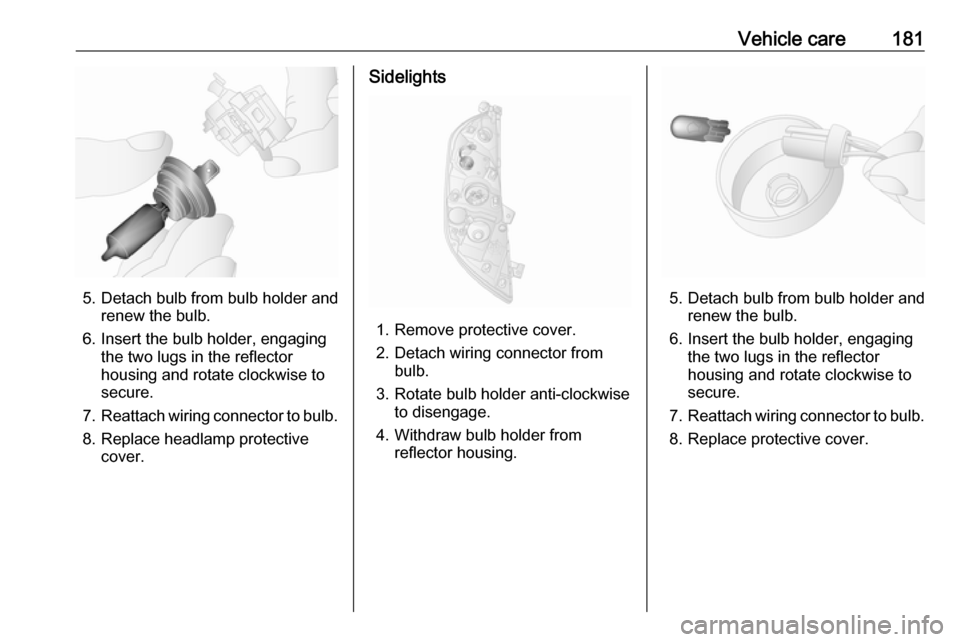
5. Detach bulb from bulb holder andrenew the bulb.
6. Insert the bulb holder, engaging the two lugs in the reflectorhousing and rotate clockwise to
secure.
7. Reattach wiring connector to bulb.
8. Replace headlamp protective cover.
Sidelights
1. Remove protective cover.
2. Detach wiring connector from bulb.
3. Rotate bulb holder anti-clockwise to disengage.
4. Withdraw bulb holder from reflector housing.
5. Detach bulb from bulb holder andrenew the bulb.
6. Insert the bulb holder, engaging the two lugs in the reflectorhousing and rotate clockwise to
secure.
7. Reattach wiring connector to bulb.
8. Replace protective cover.
Page 184 of 255
182Vehicle careAdaptive forward lightingCornering light
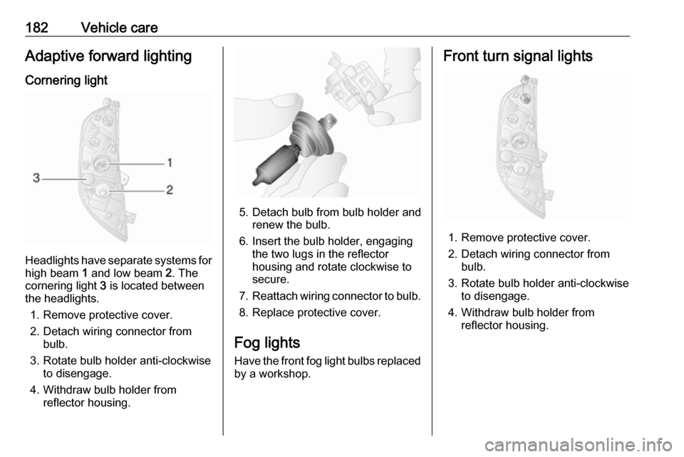
Headlights have separate systems forhigh beam 1 and low beam 2. The
cornering light 3 is located between
the headlights.
1. Remove protective cover.
2. Detach wiring connector from bulb.
3. Rotate bulb holder anti-clockwise to disengage.
4. Withdraw bulb holder from reflector housing.
5. Detach bulb from bulb holder andrenew the bulb.
6. Insert the bulb holder, engaging the two lugs in the reflectorhousing and rotate clockwise to
secure.
7. Reattach wiring connector to bulb.
8. Replace protective cover.
Fog lights
Have the front fog light bulbs replaced by a workshop.
Front turn signal lights
1. Remove protective cover.
2. Detach wiring connector from bulb.
3. Rotate bulb holder anti-clockwise to disengage.
4. Withdraw bulb holder from reflector housing.
Page 185 of 255
Vehicle care183
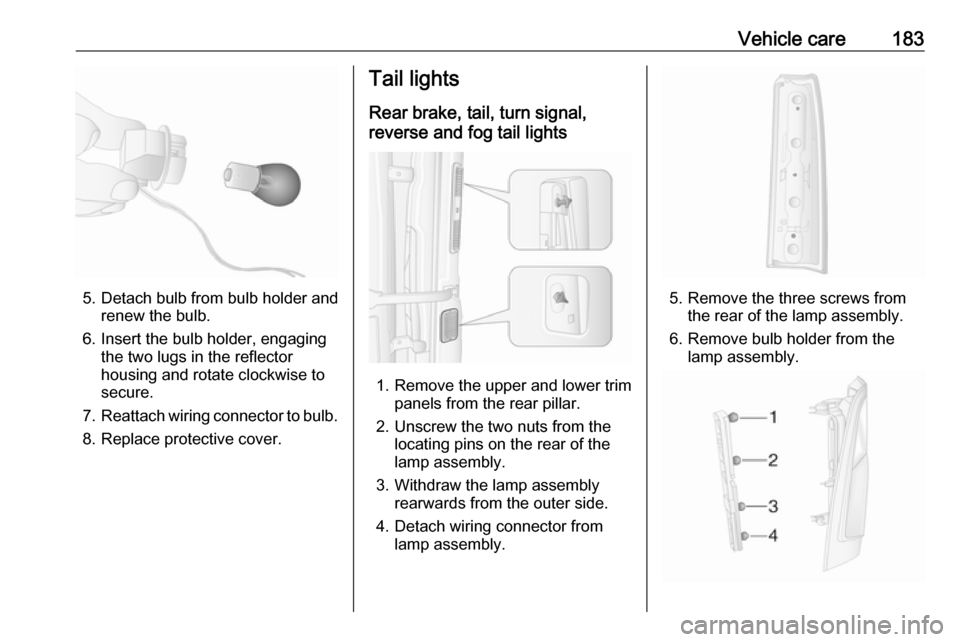
5. Detach bulb from bulb holder andrenew the bulb.
6. Insert the bulb holder, engaging the two lugs in the reflectorhousing and rotate clockwise to
secure.
7. Reattach wiring connector to bulb.
8. Replace protective cover.
Tail lights
Rear brake, tail, turn signal,
reverse and fog tail lights
1. Remove the upper and lower trim panels from the rear pillar.
2. Unscrew the two nuts from the locating pins on the rear of the
lamp assembly.
3. Withdraw the lamp assembly rearwards from the outer side.
4. Detach wiring connector from lamp assembly.
5. Remove the three screws from the rear of the lamp assembly.
6. Remove bulb holder from the lamp assembly.
Page 186 of 255
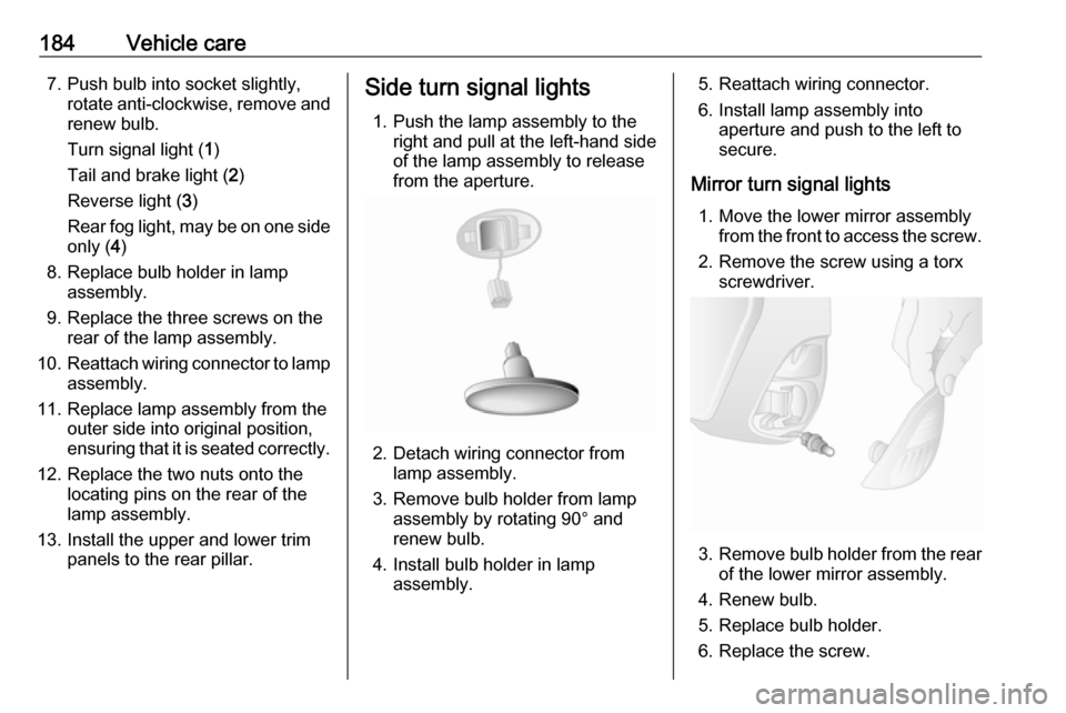
184Vehicle care7. Push bulb into socket slightly,rotate anti-clockwise, remove andrenew bulb.
Turn signal light ( 1)
Tail and brake light ( 2)
Reverse light ( 3)
Rear fog light, may be on one side
only ( 4)
8. Replace bulb holder in lamp assembly.
9. Replace the three screws on the rear of the lamp assembly.
10. Reattach wiring connector to lamp
assembly.
11. Replace lamp assembly from the outer side into original position,
ensuring that it is seated correctly.
12. Replace the two nuts onto the locating pins on the rear of the
lamp assembly.
13. Install the upper and lower trim panels to the rear pillar.Side turn signal lights
1. Push the lamp assembly to the right and pull at the left-hand side
of the lamp assembly to release
from the aperture.
2. Detach wiring connector from lamp assembly.
3. Remove bulb holder from lamp assembly by rotating 90° and
renew bulb.
4. Install bulb holder in lamp assembly.
5. Reattach wiring connector.
6. Install lamp assembly into aperture and push to the left to
secure.
Mirror turn signal lights 1. Move the lower mirror assembly from the front to access the screw.
2. Remove the screw using a torx screwdriver.
3. Remove bulb holder from the rear
of the lower mirror assembly.
4. Renew bulb.
5. Replace bulb holder.
6. Replace the screw.
Page 203 of 255

Vehicle care201not be driven. Seek the
assistance of a workshop.
21. Stow tyre repair kit under the front
seat.
Note
The driving characteristics of the repaired tyre are severely affected,therefore have this tyre replaced.
If unusual noise is heard or the
compressor becomes hot, turn
compressor off for at least
30 minutes.
The built-in safety valve opens at a
pressure of seven bar.
Note the expiry date of the kit. After
this date its sealing capability is no
longer guaranteed. Pay attention to
storage information on sealant
bottle.
Replace the used sealant bottle. Dispose of the bottle as prescribed
by applicable laws.
The compressor and sealant can be used from approx. -30 °C.Wheel changing
Some vehicles are equipped with a
tyre repair kit instead of a spare wheel
3 198.
Make the following preparations and
observe the following information:
● Park the vehicle on a level, firm and non-slippery surface. The
front wheels must be in the
straight-ahead position.
● Apply the parking brake and engage first gear or reverse gear
(manual transmission) or N
(manual transmission
automated).
● Switch off the air suspension system 3 135.
● Remove the spare wheel 3 203.
● Never change more than one wheel at a time.
● Use the jack only to change wheels in case of puncture, not
for seasonal winter or summer
tyre change.
● The jack is maintenance-free.● If the ground on which the vehicle
is standing is soft, a solid board
(max. 1 cm thick) should be
placed under the jack.
● No people or animals may be in the vehicle when it is jacked-up.
● Never crawl under a jacked-up vehicle.
● Do not start the engine when the vehicle is raised on the jack.
● Clean wheel bolts/nuts and their threads before mounting the
wheel.9 Warning
Do not grease wheel bolt, wheel
nut and wheel nut cone.
1. Remove the wheel cover using the hook supplied. Vehicle tools
3 192.
2. Install the wheel wrench ensuring that it locates securely and loosen
each wheel bolt/nut by half a turn.
Page 204 of 255
202Vehicle care
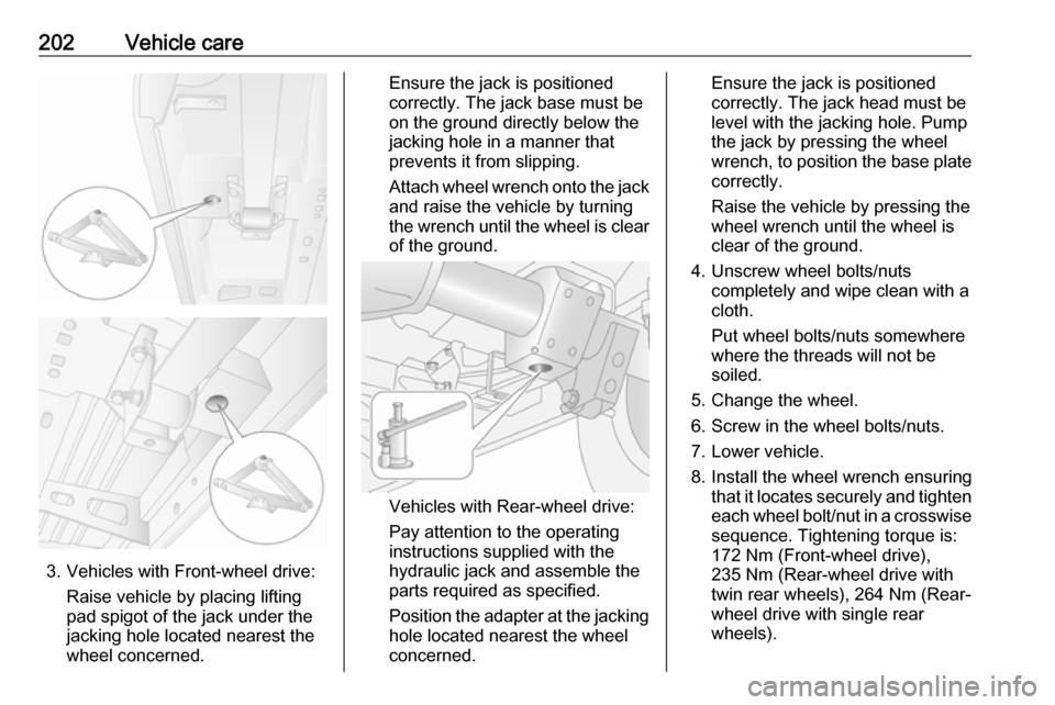
3. Vehicles with Front-wheel drive:Raise vehicle by placing lifting
pad spigot of the jack under the
jacking hole located nearest the
wheel concerned.
Ensure the jack is positioned
correctly. The jack base must be
on the ground directly below the
jacking hole in a manner that
prevents it from slipping.
Attach wheel wrench onto the jack
and raise the vehicle by turning
the wrench until the wheel is clear of the ground.
Vehicles with Rear-wheel drive:
Pay attention to the operating
instructions supplied with the
hydraulic jack and assemble the
parts required as specified.
Position the adapter at the jacking
hole located nearest the wheel
concerned.
Ensure the jack is positioned
correctly. The jack head must be
level with the jacking hole. Pump
the jack by pressing the wheel
wrench, to position the base plate
correctly.
Raise the vehicle by pressing the wheel wrench until the wheel is
clear of the ground.
4. Unscrew wheel bolts/nuts completely and wipe clean with a
cloth.
Put wheel bolts/nuts somewhere
where the threads will not be
soiled.
5. Change the wheel.
6. Screw in the wheel bolts/nuts.
7. Lower vehicle.
8. Install the wheel wrench ensuring that it locates securely and tighten
each wheel bolt/nut in a crosswise sequence. Tightening torque is:
172 Nm (Front-wheel drive),
235 Nm (Rear-wheel drive with
twin rear wheels), 264 Nm (Rear- wheel drive with single rear
wheels).
Page 205 of 255
Vehicle care2039. Refit wheel cover.Note
If applicable, fit anti-theft bolts
nearest the tyre valve (otherwise it
may not be possible to refit the wheel
cover).
10. Stow the replaced wheel 3 203
and the vehicle tools 3 192.
11. Have the new wheel balanced on the vehicle. Check the tyre
pressure of the installed tyre
3 239 and also the wheel bolt/nut
torque as soon as possible.
Have the defective tyre renewed or
repaired.
Spare wheel Some vehicles are equipped with atyre repair kit instead of a spare wheel
3 198.
If mounting a spare wheel which is
different from the other wheels, this
wheel might be classified as a
temporary spare wheel and the
corresponding speed limits apply,
even though no label indicates this.
Seek the assistance of a workshop to
check the applicable speed limit.Caution
The use of a spare wheel that is smaller than the other wheels or in combination with winter tyres
could affect driveability. Have the defective tyre replaced as soon as
possible.
The spare wheel is held under the
vehicle frame using a winch and
secured by tightening a cable using
the wheel wrench and adapters
(depending on vehicle).
It may be necessary to jack the
vehicle up to gain access to the spare
wheel on a fully loaded vehicle with a flat rear tyre.
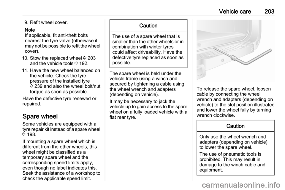
To release the spare wheel, loosen
cable by connecting the wheel
wrench and adapters (depending on
vehicle) to the slot position illustrated
and lower the wheel fully by turning
wrench clockwise.
Caution
Only use the wheel wrench and
adapters (depending on vehicle)
to lower the spare wheel.
The use of pneumatic tools is
prohibited. This may result in
damage to the winch cable and
equipment.
Page 206 of 255
204Vehicle care
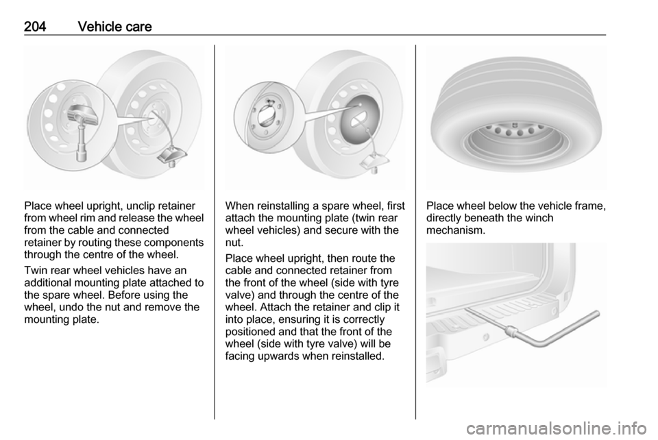
Place wheel upright, unclip retainer
from wheel rim and release the wheel
from the cable and connected
retainer by routing these components through the centre of the wheel.
Twin rear wheel vehicles have an
additional mounting plate attached to
the spare wheel. Before using the
wheel, undo the nut and remove the
mounting plate.When reinstalling a spare wheel, first
attach the mounting plate (twin rear
wheel vehicles) and secure with the
nut.
Place wheel upright, then route the
cable and connected retainer from
the front of the wheel (side with tyre
valve) and through the centre of the
wheel. Attach the retainer and clip it
into place, ensuring it is correctly
positioned and that the front of the
wheel (side with tyre valve) will be
facing upwards when reinstalled.Place wheel below the vehicle frame,
directly beneath the winch
mechanism.