ECU OPEL MOVANO_B 2018.5 Manual user
[x] Cancel search | Manufacturer: OPEL, Model Year: 2018.5, Model line: MOVANO_B, Model: OPEL MOVANO_B 2018.5Pages: 271, PDF Size: 6.5 MB
Page 88 of 271

86Storageluggage (7 kg) and all fluids (fuel
tank 90% full).
Optional equipment and
accessories increase the kerb
weight.
● Driving with a roof load increases
the sensitivity of the vehicle to
cross-winds and has a
detrimental effect on vehicle
handling due to the vehicle's
higher centre of gravity.
Distribute the load evenly and secure it properly with retaining
straps. Adjust the tyre pressure
and vehicle speed according to
the load conditions. Check and
retighten the straps frequently.
Do not drive faster than
120 km/h.
● The permissible roof load (which includes the weight of the roof
rack) is 200 kg for standard roof
variants. The roof load is the combined weight of the roof rack
and the load.
Page 132 of 271
130Climate controlManual control
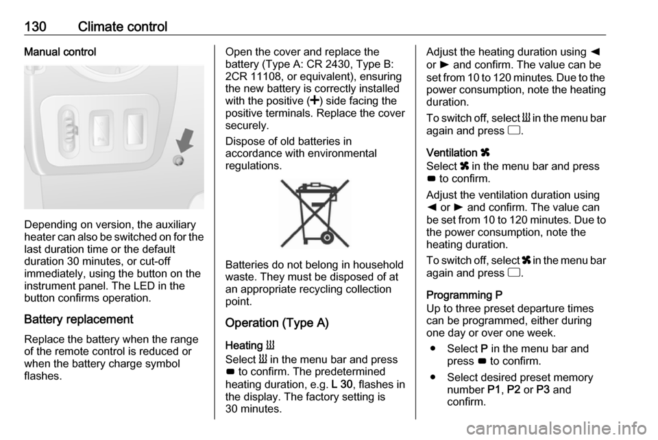
Depending on version, the auxiliary
heater can also be switched on for the
last duration time or the default
duration 30 minutes, or cut-off
immediately, using the button on the
instrument panel. The LED in the
button confirms operation.
Battery replacement
Replace the battery when the range
of the remote control is reduced or
when the battery charge symbol
flashes.
Open the cover and replace the
battery (Type A: CR 2430, Type B:
2CR 11108, or equivalent), ensuring
the new battery is correctly installed
with the positive ( <) side facing the
positive terminals. Replace the cover
securely.
Dispose of old batteries in
accordance with environmental
regulations.
Batteries do not belong in household
waste. They must be disposed of at
an appropriate recycling collection
point.
Operation (Type A)
Heating Y
Select Y in the menu bar and press
G to confirm. The predetermined
heating duration, e.g. L 30, flashes in
the display. The factory setting is 30 minutes.
Adjust the heating duration using k
or l and confirm. The value can be
set from 10 to 120 minutes. Due to the
power consumption, note the heating duration.
To switch off, select Y in the menu bar
again and press d.
Ventilation x
Select x in the menu bar and press
G to confirm.
Adjust the ventilation duration using k or l and confirm. The value can
be set from 10 to 120 minutes. Due to the power consumption, note the
heating duration.
To switch off, select x in the menu bar
again and press d.
Programming P
Up to three preset departure times
can be programmed, either during
one day or over one week.
● Select P in the menu bar and
press G to confirm.
● Select desired preset memory number P1, P2 or P3 and
confirm.
Page 159 of 271
Driving and operating157shift is not executed. This prevents
the engine from running at too low or
too high an engine speed.
If engine speed is too low, the
transmission automatically shifts to a
lower gear.
If engine speed is too high, the
transmission only switches to a higher
gear via kickdown.
Electronic drivingprogrammes
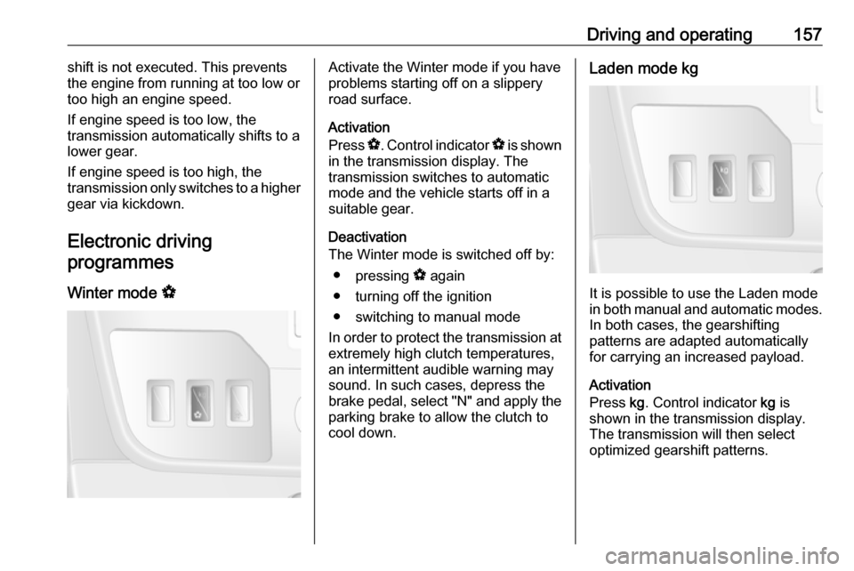
Winter mode VActivate the Winter mode if you have
problems starting off on a slippery
road surface.
Activation
Press V. Control indicator V is shown
in the transmission display. The
transmission switches to automatic
mode and the vehicle starts off in a
suitable gear.
Deactivation
The Winter mode is switched off by:
● pressing V again
● turning off the ignition
● switching to manual mode
In order to protect the transmission at extremely high clutch temperatures,
an intermittent audible warning may
sound. In such cases, depress the
brake pedal, select "N" and apply the parking brake to allow the clutch to
cool down.Laden mode kg
It is possible to use the Laden mode
in both manual and automatic modes. In both cases, the gearshifting
patterns are adapted automatically
for carrying an increased payload.
Activation
Press kg. Control indicator kg is
shown in the transmission display.
The transmission will then select
optimized gearshift patterns.
Page 185 of 271
Vehicle care183
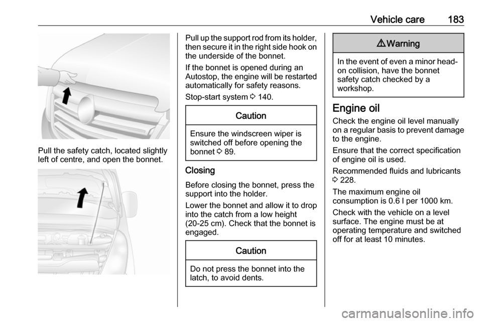
Pull the safety catch, located slightly
left of centre, and open the bonnet.
Pull up the support rod from its holder,
then secure it in the right side hook on the underside of the bonnet.
If the bonnet is opened during an Autostop, the engine will be restarted
automatically for safety reasons.
Stop-start system 3 140.Caution
Ensure the windscreen wiper is
switched off before opening the
bonnet 3 89.
Closing
Before closing the bonnet, press the
support into the holder.
Lower the bonnet and allow it to drop into the catch from a low height
(20-25 cm). Check that the bonnet is
engaged.
Caution
Do not press the bonnet into the
latch, to avoid dents.
9 Warning
In the event of even a minor head-
on collision, have the bonnet
safety catch checked by a
workshop.
Engine oil
Check the engine oil level manually on a regular basis to prevent damage
to the engine.
Ensure that the correct specification
of engine oil is used.
Recommended fluids and lubricants
3 228.
The maximum engine oil
consumption is 0.6 l per 1000 km.
Check with the vehicle on a level
surface. The engine must be at
operating temperature and switched
off for at least 10 minutes.
Page 186 of 271
184Vehicle care
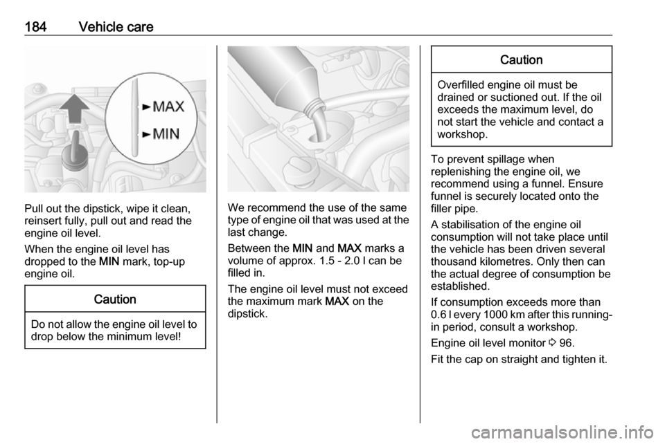
Pull out the dipstick, wipe it clean,
reinsert fully, pull out and read the
engine oil level.
When the engine oil level has
dropped to the MIN mark, top-up
engine oil.
Caution
Do not allow the engine oil level to drop below the minimum level!
We recommend the use of the same
type of engine oil that was used at the
last change.
Between the MIN and MAX marks a
volume of approx. 1.5 - 2.0 l can be
filled in.
The engine oil level must not exceed the maximum mark MAX on the
dipstick.
Caution
Overfilled engine oil must be
drained or suctioned out. If the oil exceeds the maximum level, do
not start the vehicle and contact a
workshop.
To prevent spillage when
replenishing the engine oil, we
recommend using a funnel. Ensure
funnel is securely located onto the
filler pipe.
A stabilisation of the engine oil
consumption will not take place until
the vehicle has been driven several
thousand kilometres. Only then can
the actual degree of consumption be
established.
If consumption exceeds more than
0.6 l every 1000 km after this running-
in period, consult a workshop.
Engine oil level monitor 3 96.
Fit the cap on straight and tighten it.
Page 194 of 271
192Vehicle care
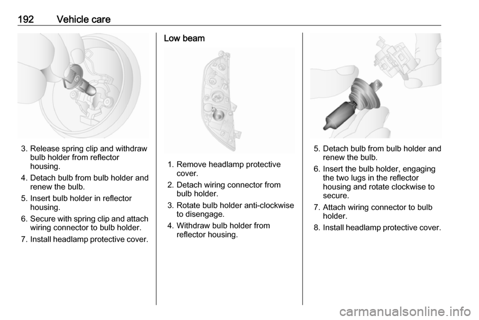
3. Release spring clip and withdrawbulb holder from reflector
housing.
4. Detach bulb from bulb holder and renew the bulb.
5. Insert bulb holder in reflector housing.
6. Secure with spring clip and attach
wiring connector to bulb holder.
7. Install headlamp protective cover.
Low beam
1. Remove headlamp protective
cover.
2. Detach wiring connector from bulb holder.
3. Rotate bulb holder anti-clockwise to disengage.
4. Withdraw bulb holder from reflector housing.
5. Detach bulb from bulb holder andrenew the bulb.
6. Insert the bulb holder, engaging the two lugs in the reflectorhousing and rotate clockwise to
secure.
7. Attach wiring connector to bulb holder.
8. Install headlamp protective cover.
Page 195 of 271
Vehicle care193Sidelights
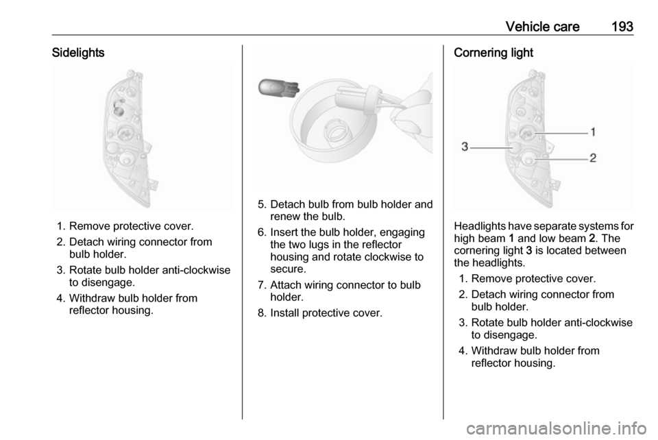
1. Remove protective cover.
2. Detach wiring connector from bulb holder.
3. Rotate bulb holder anti-clockwise to disengage.
4. Withdraw bulb holder from reflector housing.
5. Detach bulb from bulb holder andrenew the bulb.
6. Insert the bulb holder, engaging the two lugs in the reflectorhousing and rotate clockwise to
secure.
7. Attach wiring connector to bulb holder.
8. Install protective cover.
Cornering light
Headlights have separate systems for high beam 1 and low beam 2. The
cornering light 3 is located between
the headlights.
1. Remove protective cover.
2. Detach wiring connector from bulb holder.
3. Rotate bulb holder anti-clockwise to disengage.
4. Withdraw bulb holder from reflector housing.
Page 196 of 271
194Vehicle care
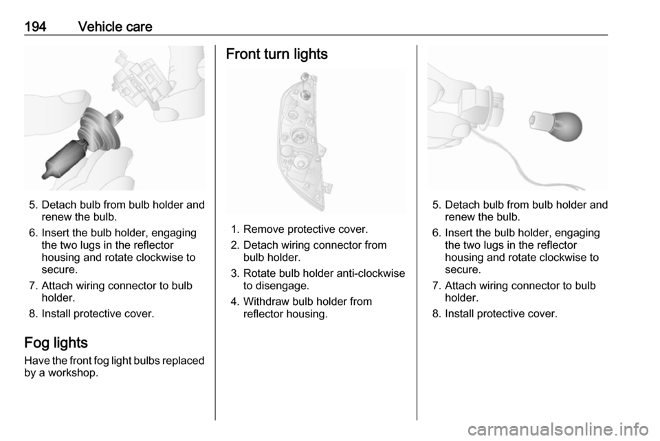
5. Detach bulb from bulb holder andrenew the bulb.
6. Insert the bulb holder, engaging the two lugs in the reflectorhousing and rotate clockwise to
secure.
7. Attach wiring connector to bulb holder.
8. Install protective cover.
Fog lights
Have the front fog light bulbs replaced by a workshop.
Front turn lights
1. Remove protective cover.
2. Detach wiring connector from bulb holder.
3. Rotate bulb holder anti-clockwise to disengage.
4. Withdraw bulb holder from reflector housing.
5. Detach bulb from bulb holder andrenew the bulb.
6. Insert the bulb holder, engaging the two lugs in the reflectorhousing and rotate clockwise to
secure.
7. Attach wiring connector to bulb holder.
8. Install protective cover.
Page 199 of 271
Vehicle care1975. Attach wiring connector to lampassembly.
6. Insert lamp assembly into aperture and push to the left to
secure.
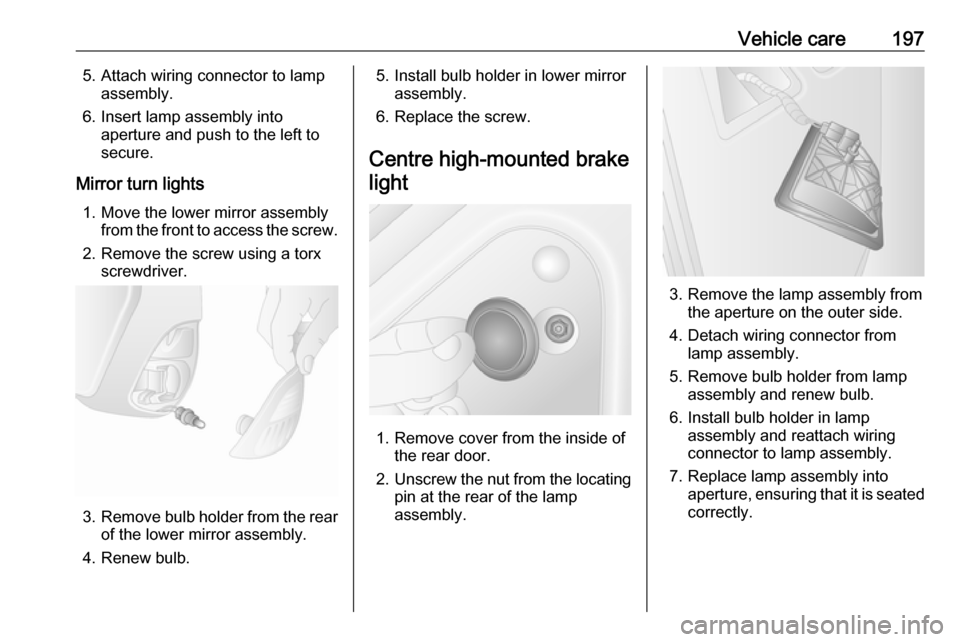
Mirror turn lights 1. Move the lower mirror assembly from the front to access the screw.
2. Remove the screw using a torx screwdriver.
3.Remove bulb holder from the rear
of the lower mirror assembly.
4. Renew bulb.
5. Install bulb holder in lower mirror assembly.
6. Replace the screw.
Centre high-mounted brake light
1. Remove cover from the inside of the rear door.
2. Unscrew the nut from the locating
pin at the rear of the lamp
assembly.
3. Remove the lamp assembly from the aperture on the outer side.
4. Detach wiring connector from lamp assembly.
5. Remove bulb holder from lamp assembly and renew bulb.
6. Install bulb holder in lamp assembly and reattach wiring
connector to lamp assembly.
7. Replace lamp assembly into aperture, ensuring that it is seated
correctly.
Page 216 of 271
214Vehicle careWheel changingSome vehicles are equipped with a
tyre repair kit instead of a spare wheel
3 211.
Make the following preparations and
observe the following information:
● Park the vehicle on a level, firm and non-slippery surface. The
front wheels must be in the
straight-ahead position.
● Apply the parking brake and engage first gear or reverse gear
(manual transmission) or N
(manual transmission
automated).
● Switch off the air suspension system 3 144.
● Remove the spare wheel 3 216.
● Never change more than one wheel at a time.
● Use the jack only to change wheels in case of puncture, not
for seasonal winter or summer
tyre change.
● The jack is maintenance-free.● If the ground on which the vehicle
is standing is soft, a solid board
(max. 1 cm thick) should be
placed under the jack.
● No people or animals may be in the vehicle when it is jacked-up.
● Never crawl under a jacked-up vehicle.
● Do not start the engine when the vehicle is raised on the jack.
● Clean wheel bolts/nuts and their threads before mounting thewheel.9 Warning
Do not grease wheel bolt, wheel
nut and wheel nut cone.
1. Remove the wheel cover using the hook supplied.
Vehicle tools 3 204.
Depending on vehicle, first
remove the bolt / nut covers by
hand then remove the wheel
cover, or press wheel cover at the points indicated by the arrows and
turn to release.
Rear-wheel drive, with twin rear
wheels: Remove the tyre valve
extender from the inner rear
wheel.
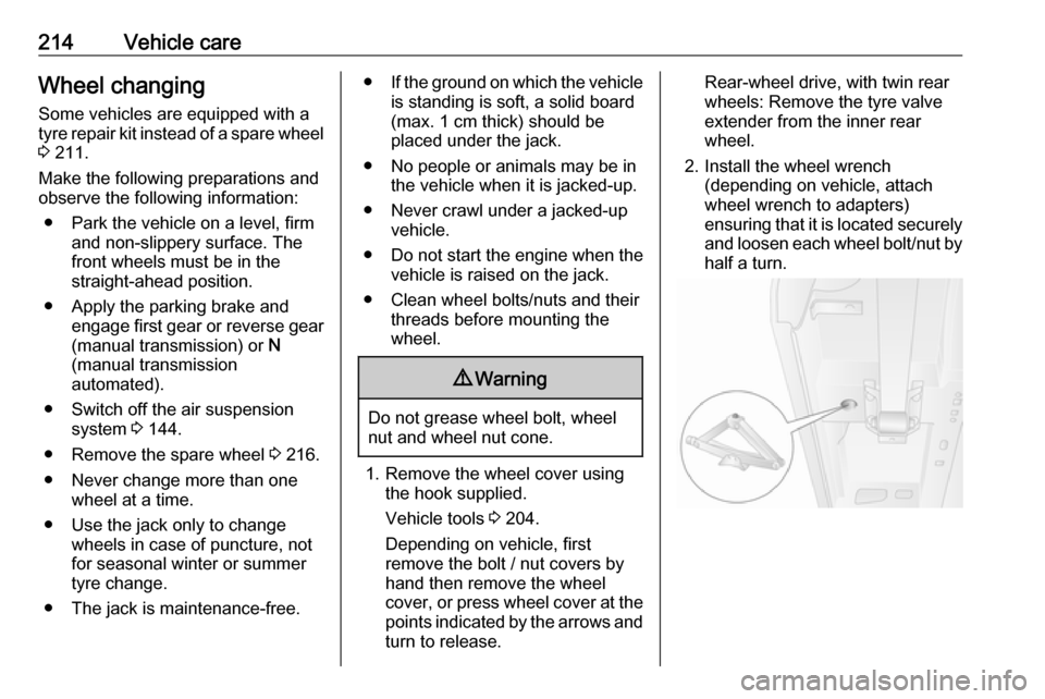
2. Install the wheel wrench (depending on vehicle, attach
wheel wrench to adapters)
ensuring that it is located securely and loosen each wheel bolt/nut byhalf a turn.