brake light OPEL MOVANO_B 2019 User Guide
[x] Cancel search | Manufacturer: OPEL, Model Year: 2019, Model line: MOVANO_B, Model: OPEL MOVANO_B 2019Pages: 251, PDF Size: 6.46 MB
Page 171 of 251
Driving and operating169●detecting a vehicle when weather
limits visibility, such as in fog,
rain, or snow
● driving during nighttime
● sensor in the windscreen or radar
unit behind the front bumper
blocked by snow, ice, slush, mud, dirt, etc.
● windscreen damaged or affected
by foreign objects, e.g. stickers
Complete attention is always required
while driving, and you should be
ready to take action and apply the
brakes and / or steer the vehicle to
avoid crashes.
Fault
In case the system requires a service,
a message is displayed in the Driver
Information Centre.
Additionally, warning lights l and
j illuminate at the same time.
When the system detects that its
function is not available, warning light l or j illuminates and stays on.
Additionally, a message in the Driver
Information Centre appears. The
system may be temporarily disrupted(for example: radar or camera
obscured by dirt, mud, snow etc.). In
this case, park the vehicle and switch
off the engine. Clean the windscreen
area around the camera and the
detection zone of the radar in the front bumper. When the warning lights and
messages still appear after starting
the vehicle again, seek the
assistance of a workshop.
Parking assist9 Warning
It is the driver who bears full
responsibility for the parking
manoeuvre.
Always check the surrounding
area while reversing and using the rear parking assist system.
The parking assist measures the
distance between the vehicle and
obstacles behind the vehicle. It
informs and warns the driver by giving acoustic signals.
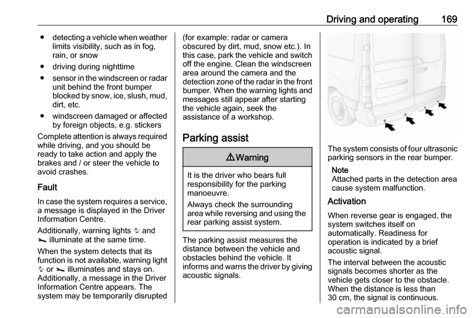
The system consists of four ultrasonic parking sensors in the rear bumper.
Note
Attached parts in the detection area
cause system malfunction.
Activation
When reverse gear is engaged, the
system switches itself on
automatically. Readiness for
operation is indicated by a brief
acoustic signal.
The interval between the acoustic
signals becomes shorter as the
vehicle gets closer to the obstacle.
When the distance is less than
30 cm, the signal is continuous.
Page 179 of 251

Driving and operating177Trailer hitch
General information
Only use towing equipment that has
been approved for your vehicle.
Entrust fitting of towing equipment at
a later date to a workshop. It may be
necessary to make changes that
affect the cooling system, heat
shields or other equipment.
Driving characteristics and towing tips
In the case of trailers with brakes,
attach the breakaway stopping cable.
Before attaching a trailer, lubricate
the coupling ball. However, do not do
so if a stabiliser, which acts on the coupling ball, is being used to reduce
snaking movements. For trailers with
low driving stability the use of a
stabiliser is recommended.
A maximum speed of 80 km/h must
not be exceeded, even in countries
where higher speeds are permitted.If the trailer starts snaking, drive more slowly, do not attempt to correct the
steering and brake sharply if
necessary.
When driving downhill, drive in the
same gear as if driving uphill and
drive at a similar speed.
Adjust tyre pressure to the value
specified for full load 3 233.
Trailer towing
Trailer loads The permissible trailer loads are
vehicle-dependent and engine-
dependent maximum values which
must not be exceeded. The actual
trailer load is the difference between
the actual gross weight of the trailer
and the actual coupling socket load
with the trailer coupled.
The permissible trailer loads are
specified in the vehicle documents. In
general, they are valid for gradients
up to max. 12%.
The permitted trailer load applies up to the specified incline and up to an
altitude of 1000 m above sea level.Since engine power decreases as
altitude increases due to the air
becoming thinner, therefore reducing
climbing ability, the permissible gross
train weight also decreases by 10%
for every 1000 m of additional
altitude. The gross train weight does
not have to be reduced when driving
on roads with slight inclines (less than 8%, e.g. motorways).
The permissible gross train weight
must not be exceeded. This weight is
specified on the identification plate
3 231.
Vertical coupling load
The vertical coupling load is the load
exerted by the trailer on the coupling
ball. It can be varied by changing the
weight distribution when loading the
trailer.
The maximum permissible vertical
coupling load is specified on the
towing equipment identification plate
and in the vehicle documents. Always aim for the maximum load, especially in the case of heavy trailers. The
vertical coupling load should never
fall below 25 kg.
Page 180 of 251
178Driving and operatingIn the case of trailer loads of
1200 kg or more, the vertical coupling load should not be less than 50 kg.
Rear axle load When the trailer is coupled and the
towing vehicle fully loaded (including all occupants), the permissible rear
axle load (see identification plate or
vehicle documents) must not be
exceeded.
Towing equipmentCaution
When operating without a trailer,
remove the coupling ball bar.
Towing equipment audible
warning
For vehicles fitted with towing
equipment, when connected to a
trailer the pitch of the audible warning
changes upon operation of the turn
lights.
The pitch of the audible warning will
change if a turn light on the trailer or
the towing vehicle fails.
Trailer stability assist
If the system detects snaking
movements, engine power is reduced
and the vehicle / trailer combination is
selectively braked until the snaking
ceases. While the system is working, keep steering wheel as still as
possible.
Trailer stability assist is a function of
the Electronic Stability Control (ESC)
3 161.Auxiliary features
Power take-off
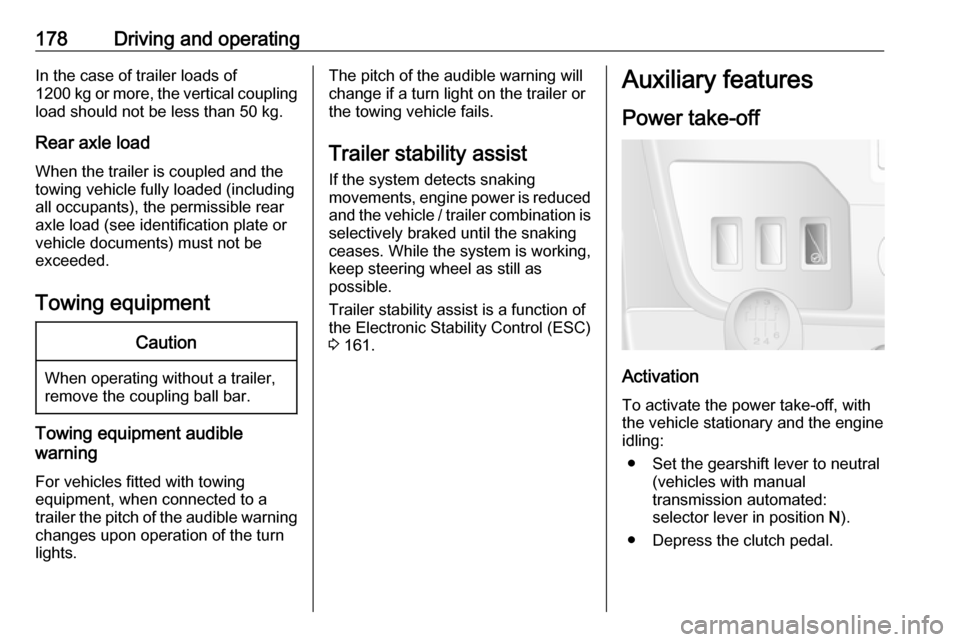
Activation
To activate the power take-off, with
the vehicle stationary and the engine
idling:
● Set the gearshift lever to neutral (vehicles with manual
transmission automated:
selector lever in position N).
● Depress the clutch pedal.
Page 182 of 251

180Vehicle careVehicle careGeneral Information...................181
Accessories and vehicle modifications .......................... 181
Vehicle storage ........................181
End-of-life vehicle recovery .....182
Vehicle checks ........................... 182
Performing work ......................182
Bonnet ..................................... 182
Engine oil ................................. 183
Engine coolant ......................... 185
Power steering fluid .................185
Washer fluid ............................ 186
Brakes ..................................... 187
Brake fluid ............................... 187
Vehicle battery ......................... 187
Diesel fuel filter ........................189
Diesel fuel system bleeding .....189
Wiper blade replacement ........190
Bulb replacement .......................191
Headlights ............................... 191
Front fog lights ......................... 194
Front turn lights .......................194
Tail lights ................................. 195
Side turn lights ......................... 196Centre high-mounted brake
light ......................................... 197
Number plate light ...................198
Interior lights ............................ 198
Instrument panel illumination ...199
Electrical system ........................200
Fuses ....................................... 200
Engine compartment fuse box . 201
Instrument panel fuse box .......201
Load compartment fuse box ....202
Vehicle tools .............................. 204
Tools ........................................ 204
Wheels and tyres .......................205
Tyres ....................................... 205
Winter tyres ............................. 206
Tyre designations ....................206
Tyre pressure .......................... 206
Tyre pressure monitoring system .................................... 207
Tread depth ............................. 209
Changing tyre and wheel size . 210 Wheel covers ........................... 210
Tyre chains .............................. 210
Tyre repair kit .......................... 211
Wheel changing .......................214
Spare wheel ............................ 216
Jump starting ............................. 218Towing....................................... 221
Towing the vehicle ...................221
Towing another vehicle ...........222
Appearance care .......................222
Exterior care ............................ 222
Interior care ............................. 224
Page 197 of 251
Vehicle care195Tail lights
Turn light, tail and brake light,
reversing light, rear fog light
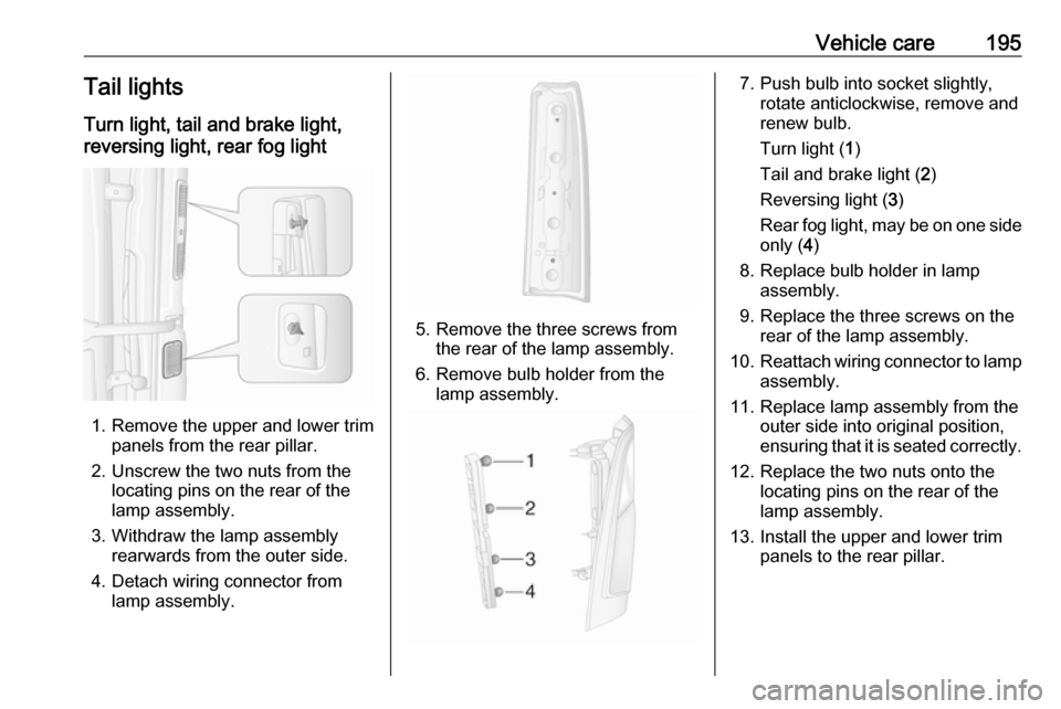
1. Remove the upper and lower trim panels from the rear pillar.
2. Unscrew the two nuts from the locating pins on the rear of the
lamp assembly.
3. Withdraw the lamp assembly rearwards from the outer side.
4. Detach wiring connector from lamp assembly.
5. Remove the three screws from the rear of the lamp assembly.
6. Remove bulb holder from the lamp assembly.
7. Push bulb into socket slightly, rotate anticlockwise, remove and
renew bulb.
Turn light ( 1)
Tail and brake light ( 2)
Reversing light ( 3)
Rear fog light, may be on one side
only ( 4)
8. Replace bulb holder in lamp assembly.
9. Replace the three screws on the rear of the lamp assembly.
10. Reattach wiring connector to lamp
assembly.
11. Replace lamp assembly from the outer side into original position,
ensuring that it is seated correctly.
12. Replace the two nuts onto the locating pins on the rear of the
lamp assembly.
13. Install the upper and lower trim panels to the rear pillar.
Page 198 of 251
196Vehicle careCrew Cab, Chassis CabTurn light, tail and brake light,
reversing light, rear fog light
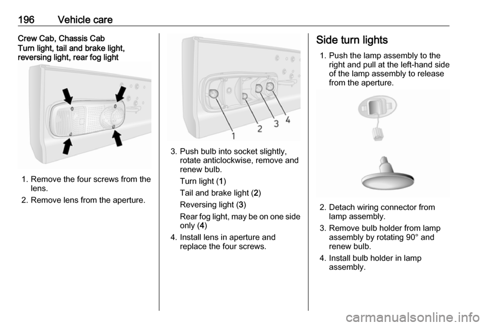
1. Remove the four screws from the lens.
2. Remove lens from the aperture.
3. Push bulb into socket slightly, rotate anticlockwise, remove and
renew bulb.
Turn light ( 1)
Tail and brake light ( 2)
Reversing light ( 3)
Rear fog light, may be on one side
only ( 4)
4. Install lens in aperture and replace the four screws.
Side turn lights
1. Push the lamp assembly to the right and pull at the left-hand side
of the lamp assembly to release
from the aperture.
2. Detach wiring connector from lamp assembly.
3. Remove bulb holder from lamp assembly by rotating 90° and
renew bulb.
4. Install bulb holder in lamp assembly.
Page 199 of 251
Vehicle care1975. Attach wiring connector to lampassembly.
6. Insert lamp assembly into aperture and push to the left to
secure.
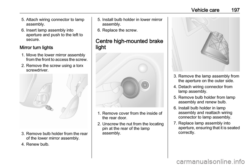
Mirror turn lights 1. Move the lower mirror assembly from the front to access the screw.
2. Remove the screw using a torx screwdriver.
3.Remove bulb holder from the rear
of the lower mirror assembly.
4. Renew bulb.
5. Install bulb holder in lower mirror assembly.
6. Replace the screw.
Centre high-mounted brake light
1. Remove cover from the inside of the rear door.
2. Unscrew the nut from the locating
pin at the rear of the lamp
assembly.
3. Remove the lamp assembly from the aperture on the outer side.
4. Detach wiring connector from lamp assembly.
5. Remove bulb holder from lamp assembly and renew bulb.
6. Install bulb holder in lamp assembly and reattach wiring
connector to lamp assembly.
7. Replace lamp assembly into aperture, ensuring that it is seated
correctly.
Page 204 of 251
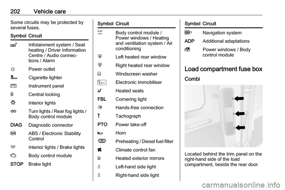
202Vehicle careSome circuits may be protected by
several fuses.SymbolCircuitZInfotainment system / Seat
heating / Driver Information
Centre / Audio connec‐
tions / Alarm?Power outletÌCigarette lightereInstrument panelUCentral locking0Interior lightsOTurn lights / Rear fog lights / Body control moduleDIAGDiagnostic connectoruABS / Electronic Stability
ControldInterior lights / Brake lightsZBody control moduleSTOPBrake lightSymbolCircuitIBody control module /
Power windows / Heating
and ventilation system / Air
conditioningmLeft heated rear windownRight heated rear windowRWindscreen washerMElectronic immobiliserUHeated seatsFBLCornering lightlHands-free connection&TachographPTOPower take-offjHornÍPreheating / Diesel fuel filterxClimate control fandHeated exterior mirrorsTLeft-hand side lightSRight-hand side lightSymbolCircuitONavigation systemADPAdditional adaptations,Power windows / Body
control module
Load compartment fuse box
Combi
Located behind the trim panel on the
right-hand side of the load
compartment, beside the rear door.
Page 223 of 251
Vehicle care221Towing
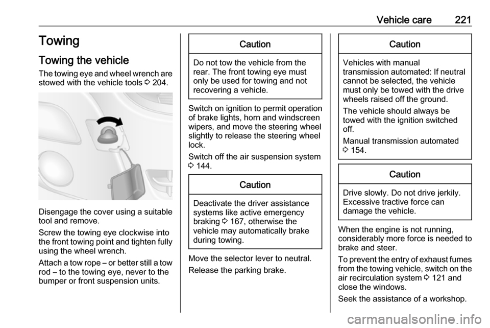
Towing the vehicle The towing eye and wheel wrench are stowed with the vehicle tools 3 204.
Disengage the cover using a suitable
tool and remove.
Screw the towing eye clockwise into
the front towing point and tighten fully using the wheel wrench.
Attach a tow rope – or better still a tow
rod – to the towing eye, never to the
bumper or front suspension units.
Caution
Do not tow the vehicle from the
rear. The front towing eye must
only be used for towing and not
recovering a vehicle.
Switch on ignition to permit operation
of brake lights, horn and windscreen
wipers, and move the steering wheel
slightly to release the steering wheel
lock.
Switch off the air suspension system 3 144.
Caution
Deactivate the driver assistance
systems like active emergency
braking 3 167, otherwise the
vehicle may automatically brake during towing.
Move the selector lever to neutral.
Release the parking brake.
Caution
Vehicles with manual
transmission automated: If neutral cannot be selected, the vehiclemust only be towed with the drive
wheels raised off the ground.
The vehicle should always be
towed with the ignition switched
off.
Manual transmission automated
3 154.
Caution
Drive slowly. Do not drive jerkily.
Excessive tractive force can
damage the vehicle.
When the engine is not running,
considerably more force is needed to
brake and steer.
To prevent the entry of exhaust fumes
from the towing vehicle, switch on the air recirculation system 3 121 and
close the windows.
Seek the assistance of a workshop.
Page 241 of 251

Customer information239Operating data in the vehicleControl units process data for
operation of the vehicle.
This data includes, e.g.: ● vehicle status information (e.g. speed, movement delay, lateral
acceleration, wheel rotation rate,
"seat belts fastened" display)
● ambient conditions (e.g. temperature, rain sensor,
distance sensor)
As a rule such data is transient, not
stored for longer than an operational
cycle, and only processed on board
the vehicle itself. Control units often
include data storage (including the
vehicle key). This is used to allow
information to be documented
temporarily or permanently on vehicle
condition, component stress,
maintenance requirements and
technical events and errors.Depending on technical equipment
level, the data stored is as follows:
● system component operating states (e.g. fill level, tyre
pressure, battery status)
● faults and defects in important system components (e.g. lights,brakes)
● system reactions in special driving situations (e.g. triggering
of an airbag, actuation of the
stability control systems)
● information on events damaging the vehicle
● for electric vehicles the amount of
charge in the high-voltage
battery, estimated range
In special cases (e.g. if the vehicle
has detected a malfunction), it may be
necessary to save data that would
otherwise just be volatile.
When you use services (e.g. repairs,
maintenance), the operating data
saved can be read together with the
vehicle identification number and
used when necessary. Staff working
for the service network ( e.g. garages,
manufacturers) or third parties (e.g.breakdown services) can read the
data from the vehicle. The same
applies to warranty work and quality
assurance measures.
Data is generally read via the OBD
(On-Board Diagnostics) port
prescribed by law in the vehicle. The operating data which is read out,
documents the technical condition of
the vehicle or individual components
and assists with fault diagnosis,
compliance with warranty obligations
and quality improvement. This data,
in particular information on
component stress, technical events,
operator errors and other faults, is
transmitted to the manufacturer
where appropriate, together with the
vehicle identification number. The
manufacturer is also subject to
product liability. The manufacturer
potentially also uses operating data
from vehicles for product recalls. This
data can also be used to check
customer warranty and guarantee
claims.
Fault memories in the vehicle can be
reset by a service company when
carrying out servicing or repairs or at
your request.