compression ratio OPEL VECTRA 1988 Service User Guide
[x] Cancel search | Manufacturer: OPEL, Model Year: 1988, Model line: VECTRA, Model: OPEL VECTRA 1988Pages: 525, PDF Size: 58.26 MB
Page 204 of 525
Oil pick-up pipe bracket to cylinder block . . . . . . . . . . . . . . . . . . . . . . .64
Oil pick-up pipe to oil pump . . . . . . . . . . . . . . . . . . . . . . . . . . . . . . . . . .86
Oil pipes to radiator . . . . . . . . . . . . . . . . . . . . . . . . . . . . . . . . . . . . . . . .2216
Oil pressure switch to oil pump:
1.4 and 1.6 litre, (except C16 NZ2) . . . . . . . . . . . . . . . . . . . . . . . . . .3022
C16 NZ2, 1.8 and 2.0 litre . . . . . . . . . . . . . . . . . . . . . . . . . . . . . . . . . .4030
Oil pressure relief valve to oil pump . . . . . . . . . . . . . . . . . . . . . . . . . . . .3022
Oil pump cover to oil pump . . . . . . . . . . . . . . . . . . . . . . . . . . . . . . . . . .64
Oil pump to cylinder block . . . . . . . . . . . . . . . . . . . . . . . . . . . . . . . . . . .64
Oxygen sensor to exhaust manifold . . . . . . . . . . . . . . . . . . . . . . . . . . . .3022
Power steering pump bracket to support:
C16 NZ2, 1.8 and 2.0 litre . . . . . . . . . . . . . . . . . . . . . . . . . . . . . . . . . .1813
Power steering pump to support . . . . . . . . . . . . . . . . . . . . . . . . . . . . . .2518
Right engine mounting to subframe . . . . . . . . . . . . . . . . . . . . . . . . . . . .6548
Shackle to alternator . . . . . . . . . . . . . . . . . . . . . . . . . . . . . . . . . . . . . . . .2518
Spark plugs . . . . . . . . . . . . . . . . . . . . . . . . . . . . . . . . . . . . . . . . . . . . . . .2518
Starter to cylinder block (M10) . . . . . . . . . . . . . . . . . . . . . . . . . . . . . . . .4533
Starter to cylinder block (M12) . . . . . . . . . . . . . . . . . . . . . . . . . . . . . . . .6044
Sump:
1.4 and 1.6 litre, (except C16 NZ2) . . . . . . . . . . . . . . . . . . . . . . . . . . .86
C16 NZ2, 1.8 and 2.0 litre . . . . . . . . . . . . . . . . . . . . . . . . . . . . . . . . . .1511
Sump drain plug . . . . . . . . . . . . . . . . . . . . . . . . . . . . . . . . . . . . . . . . . . .5541
Support to cylinder block . . . . . . . . . . . . . . . . . . . . . . . . . . . . . . . . . . . .3526
Temperature sender to cylinder head . . . . . . . . . . . . . . . . . . . . . . . . . . .2015
Thermostat housing:
1.4 and 1.6 litre, (except C16 NZ2) . . . . . . . . . . . . . . . . . . . . . . . . . . .107
C16 NZ2, 1.8 and 2.0 litre . . . . . . . . . . . . . . . . . . . . . . . . . . . . . . . . . .1511
Timing belt tensioner to oil pump:
1.4 and 1.6 litre, (except C16 NZ2) . . . . . . . . . . . . . . . . . . . . . . . . . . .5541
Timing belt cover to oil pump/camshaft housing:
1.4 and 1.6 litre, (except C16 NZ2) . . . . . . . . . . . . . . . . . . . . . . . . . . .129
C16 NZ2, 1.8 and 2.0 litre . . . . . . . . . . . . . . . . . . . . . . . . . . . . . . . . . .64
Timing belt drive gear to crankshaft:
C16 NZ2, 1.8 and 2.0 litre:
Stage 1 . . . . . . . . . . . . . . . . . . . . . . . . . . . . . . . . . . . . . . . . . . . . . .13096
Stage 2 . . . . . . . . . . . . . . . . . . . . . . . . . . . . . . . . . . . . . . . . . . . . . .Angle tighten by between 40º to 50º
Transmission to engine (M10) . . . . . . . . . . . . . . . . . . . . . . . . . . . . . . . . .4533
Transmission to engine (M12) . . . . . . . . . . . . . . . . . . . . . . . . . . . . . . . . .6044
1General description
General
The engine is of four-cylinder, in-line single
or double overhead camshaft type (depending
on model), mounted transversely at the front
of the vehicle.
The crankshaft runs in five shell-type
bearings, and the centre bearing incorporates
a thrust bearing shell to control crankshaft
endfloat.
The connecting rods are attached to the
crankshaft by horizontally split shell-type
big-end bearings. On single overhead
camshaft (SOHC) models, the pistons are
attached to the connecting rods by gudgeon
pins, which are an interference fit in the
connecting rod small-end bore. The
aluminium alloy pistons are fitted with three
piston rings: two compression rings and an oil
control ring.
The camshaft on SOHC engines is driven
from the crankshaft by a toothed composite
rubber belt. Each cylinder has two valves (oneinlet and one exhaust), operated through
rocker arms that are supported at their pivot
ends by hydraulic self-adjusting valve lifters
(tappets).
The inlet and exhaust valves are each
closed by a single valve spring, and operate in
guides pressed into the cylinder head.
A gear-type oil pump is located in a housing
attached to the front of the cylinder block, and
is driven directly from the crankshaft. A
full-flow type oil filter is fitted.
The distributor is driven directly from the
end of the camshaft. On carburettor models,
the mechanical fuel pump is operated from
the front end of the camshaft. The coolant
pump is located at the front of the cylinder
block, and is driven by the timing belt.
Chapter 2A describes the SOHC engine
repair procedures. Many repairs and specifi-
cations to the DOHC engine are similar to the
2.0 litre SOHC. However where they differ,
details can be found in Chapter 2B.
Engine identification codes -
general
Before ordering spare parts, or carrying out
any repair or overhaul operations on the
engine, it is essential to identify the exactengine type being worked on. Later engines,
although outwardly similar in appearance,
often have significant differences in repair
procedures, even though they may be of the
same displacement and model year.
The following sub-Sections in this Chapter
are mainly specific to engine type, as will be
noted from the sub-Section headings. Check
the engine identification code first, which is
located on a horizontal surface on the exhaust
manifold side of the cylinder block, at the
distributor end. On later engines, the code is
on the cylinder block-to-transmission flange,
next to the engine oil dipstick.
2Crankcase ventilation
system - description and
maintenance
2
Description
1A crankcase ventilation system is fitted to
all models, but the systems differ in detail
depending on the model concerned.
2Oil fumes and blow-by gases (combustion
gases that have passed by the piston rings)
are drawn from the crankcase into the area of
SOHC engine procedures 2A•7
2A
Page 205 of 525
the cylinder head above the camshaft(s)
through a hose. From here the gases are
drawn into the inlet manifold/throttle body (as
applicable) and/or the air box on the
carburettor (where applicable), where they are
re-burnt with fresh air/fuel mixture, hence
reducing harmful exhaust emissions.
Maintenance
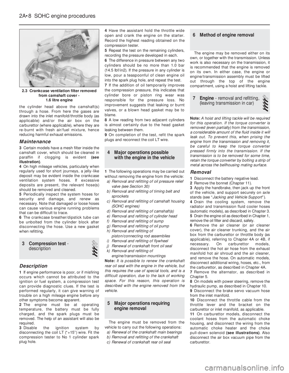
3Certain models have a mesh filter inside the
camshaft cover, which should be cleaned in
paraffin if clogging is evident (see
illustration).
4On high mileage vehicles, particularly when
regularly used for short journeys, a jelly-like
deposit may be evident inside the crankcase
ventilation system hoses. If excessive
deposits are present, the relevant hose(s)
should be removed and cleaned.
5Periodically inspect the system hoses for
security and damage, and renew as
necessary. Note that damaged or loose hoses
can cause various engine running problems
that can be difficult to trace.
6The crankcase breather/dipstick tube can
be unbolted from the cylinder block after
disconnecting the hose. Use a new gasket
when refitting.
3Compression test -
description
3
Description
1If engine performance is poor, or if misfiring
occurs which cannot be attributed to the
ignition or fuel system, a compression test
can provide diagnostic clues. If the test is
performed regularly, it can give warning of
trouble on a high mileage engine before any
other symptoms become apparent.
2The engine must be at operating
temperature, the battery must be fully
charged, and the spark plugs must be
removed. The help of an assistant will also be
required.
3Disable the ignition system by
disconnecting the coil LT (“+15”) wire. Fit the
compression tester to No 1 cylinder spark
plug hole.4Have the assistant hold the throttle wide
open and crank the engine on the starter.
Record the highest reading obtained on the
compression tester.
5Repeat the test on the remaining cylinders,
recording the pressure developed in each.
6The difference in pressure between any two
cylinders should be no more than 1.0 bar
(14.5 lbf/in2). If the pressure in any cylinder is
low, pour a teaspoonful of clean engine oil
into the spark plug hole, and repeat the test.
7If the addition of oil temporarily improves
the compression pressure, this indicates that
cylinder bore or piston ring wear was
responsible for the pressure loss. No
improvement suggests that leaking or burnt
valves, or a blown head gasket may be to
blame.
8A low reading from two adjacent cylinders
is almost certainly due to the head gasket
leaking between them.
9On completion of the test, refit the spark
plugs and reconnect the coil LT wire.
4Major operations possible
with the engine in the vehicle
1The following operations may be carried out
without removing the engine from the vehicle:
a)Removal and refitting of oil pressure relief
valve (see Section 30)
b)Removal and refitting of timing belt and
sprockets
c)Removal and refitting of camshaft housing
(SOHC engines)
d)Removal and refitting of camshaft(s)
e)Removal and refitting of cylinder head
f)Removal and refitting of sump
g)Removal and refitting of oil pump
h)Removal and refitting of
piston/connecting rod assemblies
i)Removal and refitting of flywheel
j)Renewal of crankshaft front oil seal
k)Removal and refitting of
engine/transmission mountings
Note: It is possible to renew the crankshaft
rear oil seal with the engine in the vehicle, but
this requires the use of special tools, and is a
difficult operation, due to the lack of working
space. For this reason, this operation is
described with the engine removed from the
vehicle.
5Major operations requiring
engine removal
The engine must be removed from the
vehicle to carry out the following operations:
a)Renewal of the crankshaft main bearings
b)Removal and refitting of the crankshaft
c)Renewal of crankshaft rear oil seal
6Method of engine removal
The engine may be removed either on its
own, or together with the transmission. Unless
work is also necessary on the transmission, it
is recommended that the engine is removed
on its own. In either case, the engine or
engine/transmission assembly must be lifted
out through the top of the engine
compartment, using a hoist and lifting tackle.
7Engine - removal and refitting,
(leaving transmission in car)
4
Note: A hoist and lifting tackle will be required
for this operation.If the torque converter is
removed (even partially) from the transmission,
a considerable amount of the fluid inside it will
leak out. To prevent this, when prising the
engine from the transmission and removing it,
be careful to keep the torque converter
pressed firmly into the transmission. If the
transmission is to be removed for some time,
retain the torque converter by bolting a strip of
metal across the bellhousing mating surface.
Removal
1Disconnect the battery negative lead.
2Remove the bonnet (Chapter 11).
3Apply the handbrake, then jack up the front
of the vehicle, and support securely on axle
stands (see “Jacking and Vehicle Support”).
4Drain the cooling system, remove the
radiator and transmission fluid cooler hoses
(automatic models), as described in Chapter 3.
5Drain the engine oil as described in Chapter 1,
remove the oil filter and discard, safely.
6Remove the air cleaner (or air cleaner
cover), the air cleaner trunking, and the air
box from the carburettor or throttle body (as
applicable), referring to Chapter 4A or 4B, if
necessary. On carburettor models,
disconnect the hot air hose from the exhaust
manifold hot air shroud and the air cleaner,
and remove the hose. On automatic models,
disconnect additional wiring, hoses, etc., from
the carburettor, as described in Chapter 4A.
7Remove the alternator, as described in
Chapter 5.
8On models with power steering, remove the
hydraulic pump, as described in Chapter 10.
9Disconnect the brake servo vacuum hose
from the inlet manifold.
10Disconnect the throttle cable from the
throttle lever and the bracket on the
carburettor or inlet manifold, as applicable.
11On carburettor models, disconnect the
coolant hoses from the automatic choke
housing, and disconnect the wiring from the
automatic choke heater and the choke
pull-down solenoid (see illustrations). Also
disconnect the air box vacuum pipe from the
carburettor.
2A•8SOHC engine procedures
2.3 Crankcase ventilation filter removed
from camshaft cover -
1.6 litre engine
Page 213 of 525
32Release the securing clips and remove the
main outer timing belt cover, then unclip the
smaller outer timing belt cover from the
coolant pump.
33Turn the crankshaft through at least
quarter of a turn clockwise using a socket or
spanner on the crankshaft sprocket bolt.
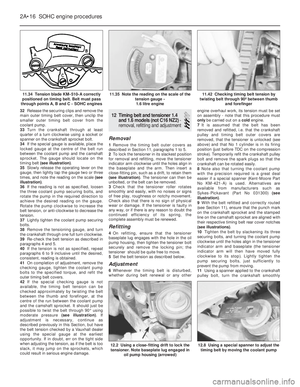
34If the special gauge is available, place the
locked gauge at the centre of the belt run
between the coolant pump and the camshaft
sprocket. The gauge should locate on the
timing belt (see illustration).
35Slowly release the operating lever on the
gauge, then lightly tap the gauge two or three
times, and note the reading on the scale (see
illustration).
36If the reading is not as specified, loosen
the three coolant pump securing bolts, and
rotate the pump in the required direction to
achieve the desired reading on the gauge.
Rotate the pump clockwise to increase the
belt tension, or anti-clockwise to decrease the
tension.
37Lightly tighten the coolant pump securing
bolts.
38Remove the tensioning gauge, and turn
the crankshaft through one full turn clockwise.
39Re-check the belt tension as described in
paragraphs 4 and 5.
40If the tension is not as specified, repeat
paragraphs 6 to 9 inclusive until the desired,
consistent, reading is obtained.
41On completion of adjustment, remove the
checking gauge, tighten the coolant pump
bolts to the specified torque, and refit the
outer timing belt covers.
42If the special checking gauge is not
available, the timing belt tension can be
checked approximately by twisting the belt
between the thumb and forefinger, at the
centre of the run between the coolant pump
and the camshaft sprocket. It should just be
possible to twist the belt through 90°using
moderate pressure (see illustration). If
adjustment is necessary, continue as
described previously in this Section, but have
the belt tension checked by a Vauxhall dealer
using the special gauge at the earliest
opportunity. If in doubt, err on the tight side
when adjusting the tension, as if the belt is too
slack, it may jump on the sprockets, which
could result in serious engine damage.12Timing belt and tensioner 1.4
and 1.6 models (not C16 NZ2) -
removal, refitting and adjustment
3
Removal
1Remove the timing belt outer covers as
described in Section 11, paragraphs 1 to 5.
2To lock the tensioner in its slackest position
for removal and refitting, move the tensioner
indicator arm clockwise until the holes align in
the baseplate and the arm. Then insert a
close-fitting pin, such as a drift, to retain them
(see illustration). The tensioner can then be
unbolted, or the belt can be removed.
3Check that the tensioner roller rotates
smoothly and easily, with no noises or signs
of free play, roughness or notchy movement.
Check also that there is no sign of physical
wear or damage. If the tensioner is faulty in
any way, or if there is any reason to doubt the
continued efficiency of its spring, the
complete assembly must be renewed.
Refitting
4On refitting, ensure that the tensioner
baseplate lug engages with the hole in the oil
pump housing, then tighten the tensioner bolt
securely and remove the locking pin; the
tensioner should be quite free to move.
5Set the belt tension as described below.
Adjustment
6Whenever the timing belt is disturbed,
whether during belt renewal or any otherengine overhaul work, its tension must be set
on assembly - note that this procedure must
only be carried out on a cold engine.
7It is assumed that the belt has been
removed and refitted, i.e. that the crankshaft
pulley and timing belt outer covers are
removed, that the tensioner is unlocked (see
above) and that No 1 cylinder is in its firing
position (just before TDC on the compression
stroke). Temporarily refit the crankshaft pulley
bolt and remove the spark plugs so that the
crankshaft can be rotated easily.
8Note also that turning the coolant pump
with the precision required is a great deal
easier if a special spanner (Kent-Moore Part
No KM-421-A) is used. Alternatives are
available from manufacturers such as
Sykes-Pickavant (Part No 031300) (see
illustration).
9With the belt refitted and correctly routed
(see Section 11), ensure that the punch mark
on the crankshaft sprocket and the stamped
line on the camshaft sprocket are aligned with
their respective timing belt rear cover notches
(see illustrations).
10Tighten the belt by slackening its three
securing bolts, and turning the coolant pump
clockwise until the holes align in the tensioner
indicator arm and baseplate (the tensioner
indicator arm will then have moved fully
clockwise to its stop). Lightly tighten the
pump securing bolts, just sufficiently to
prevent the pump from moving.
11Using a spanner applied to the crankshaft
pulley bolt, turn the crankshaft smoothly
2A•16SOHC engine procedures
11.34 Tension blade KM-510-A correctly
positioned on timing belt. Belt must pass
through points A, B and C - SOHC engines11.42 Checking timing belt tension by
twisting belt through 90º between thumb
and forefinger
12.8 Using a special spanner to adjust the
timing belt by moving the coolant pump12.2 Using a close-fitting drift to lock the
tensioner. Note baseplate lug engaged in
oil pump housing (arrowed)
11.35 Note the reading on the scale of the
tension gauge -
1.6 litre engine
Page 228 of 525
7If any of the ring end gaps exceed the
specified tolerance, the relevant rings will have
to be renewed, and if the ring grooves in the
pistons are worn, new pistons may be required.
8Clean out the piston ring grooves using a
piece of old piston ring as a scraper. Take
care not to scratch the surface of the pistons.
Protect your fingers, piston ring edges are
sharp. Also probe the groove oil return holes,
to ensure that they are not blocked.
9Check the cylinder bores for signs of wear
ridges towards the top of the bores. If wear
ridges are evident, and new piston rings are
being fitted, the top ring must be stepped to
clear the wear ridge, or the bore must be
de-ridged using a scraper.
10Fit the oil control ring sections with the
lower steel ring gap offset 25 to 50 mm to the
right of the spreader ring gap, and the upper
steel ring gap offset by the same distance to
the left of the spreader ring gap.
11Fit the lower compression ring, noting that
the ring is tapered or stepped. The ring should
be fitted with the word “TOP” uppermost.
12Fit the upper compression ring, and offset
the ring gap by 180°to the lower compression
ring gap. If a stepped ring is being fitted, fit
the ring with the smaller diameter of the step
uppermost.
13If new pistons are to be fitted, they must
be selected from the grades available, after
measuring the cylinder bores as described in
Section 36.
14Normally the appropriate oversize pistons
are supplied by the dealer when the block is
rebored.15Whenever new piston rings are being
installed, the glaze on the original cylinder
bores should be “broken”, using either
abrasive paper or a glaze-removing tool in an
electric drill. If abrasive paper is used, use
strokes at 60°to the bore centre line, to create
a cross-hatching effect.
34Crankshaft and bearings -
removal and refitting
4
Note: New main bearing cap bolts must be
used on refitting
Removal
1With the engine removed from the vehicle,
continue as follows.
2Remove the cylinder head, as described
previously in Section 20.
3Remove the sump, oil pick-up pipe and
sump baffle (where applicable), as described
in Section 29.
4Remove the oil pump, as described in
Section 30.
5Remove the flywheel or flexplate (if
applicable), as described in Sections 25 and
26.
6Remove the pistons and connecting rods,
as described in Section 32.
7Invert the engine so that it is standing on
the top face of the cylinder block.
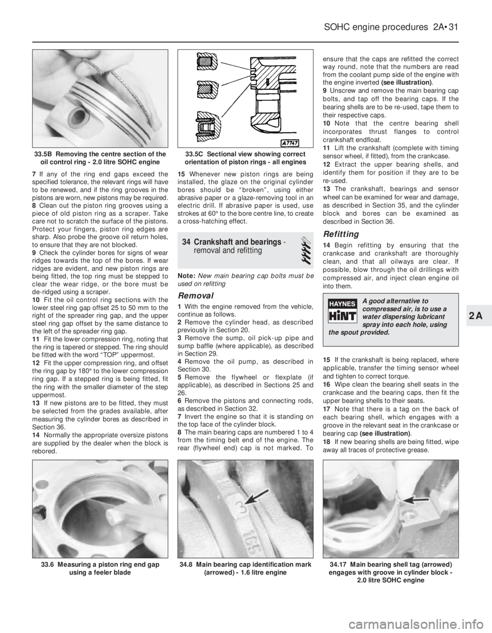
8The main bearing caps are numbered 1 to 4
from the timing belt end of the engine. The
rear (flywheel end) cap is not marked. Toensure that the caps are refitted the correct
way round, note that the numbers are read
from the coolant pump side of the engine with
the engine inverted (see illustration).
9Unscrew and remove the main bearing cap
bolts, and tap off the bearing caps. If the
bearing shells are to be re-used, tape them to
their respective caps.
10Note that the centre bearing shell
incorporates thrust flanges to control
crankshaft endfloat.
11Lift the crankshaft (complete with timing
sensor wheel, if fitted), from the crankcase.
12Extract the upper bearing shells, and
identify them for position if they are to be
re-used.
13The crankshaft, bearings and sensor
wheel can be examined for wear and damage,
as described in Section 35, and the cylinder
block and bores can be examined as
described in Section 36.
Refitting
14Begin refitting by ensuring that the
crankcase and crankshaft are thoroughly
clean, and that all oilways are clear. If
possible, blow through the oil drillings with
compressed air, and inject clean engine oil
into them.
15If the crankshaft is being replaced, where
applicable, transfer the timing sensor wheel
and tighten to correct torque.
16Wipe clean the bearing shell seats in the
crankcase and the bearing caps, then fit the
upper bearing shells to their seats.
17Note that there is a tag on the back of
each bearing shell, which engages with a
groove in the relevant seat in the crankcase or
bearing cap (see illustration).
18If new bearing shells are being fitted, wipe
away all traces of protective grease.
SOHC engine procedures 2A•31
33.6 Measuring a piston ring end gap
using a feeler blade34.8 Main bearing cap identification mark
(arrowed) - 1.6 litre engine34.17 Main bearing shell tag (arrowed)
engages with groove in cylinder block -
2.0 litre SOHC engine
33.5C Sectional view showing correct
orientation of piston rings - all engines33.5B Removing the centre section of the
oil control ring - 2.0 litre SOHC engine
2A
A good alternative to
compressed air, is to use a
water dispersing lubricant
spray into each hole, using
the spout provided.
Page 252 of 525
The pages that follow provide an easy-reference guide to the more
common problems that may occur during the operation of the vehicle.
These problems and their possible causes are grouped under headings
denoting various components or systems, such as Engine, Cooling
system, etc. The Chapter and/or Section that deals with the problem is
also shown in brackets. Whatever the fault, certain basic principles
apply. These are as follows:
Verify the fault. This is simply a matter of being sure that you know
what the symptoms are before starting work. This is particularly
important if you are investigating a fault for someone else, who may
not have described it very accurately.
Do not overlook the obvious. For example, if the vehicle will not start,
is there petrol in the tank? (Do not take anyone else’s word on this
particular point, and do not trust the fuel gauge either!) If an electrical
fault is indicated, look for loose or broken wires before digging out the
test gear.Cure the disease, not the symptom. Substituting a flat battery with a
fully charged one will get you off the hard shoulder, but if the
underlying cause is not attended to, the new battery will go the same
way. Similarly, changing oil-fouled spark plugs for a new set will get
you moving again, but remember that the reason for the fouling (if it
was not simply an incorrect grade of plug) will have to be established
and corrected.
Do not take anything for granted. Particularly, do not forget that a
“new” component may itself be defective (especially if it’s been rattling
around in the boot for months). Also do not leave components out of a
fault diagnosis sequence just because they are new or recently fitted.
When you do finally diagnose a difficult fault, you will probably realise
that all the evidence was there from the start.
Engine fails to rotate when attempting to start
MBattery terminal connections loose or corroded (Chapter 1).
MBattery discharged or faulty (Chapter 5).
MBroken, loose or disconnected wiring in the starting circuit
(Chapter 5).
MDefective starter solenoid or switch (Chapter 5).
MDefective starter motor (Chapter 5).
MStarter pinion or flywheel ring gear teeth loose or broken
(Chapters 2A and 5).
MEngine earth strap broken or disconnected (Chapter 5).
Engine rotates, but will not start
MFuel tank empty.
MBattery discharged (engine rotates slowly), (Chapter 5).
MBattery terminal connections loose or corroded (Chapter 1).
MIgnition components damp or damaged (Chapters 1 and 5).
MBroken, loose or disconnected wiring in the ignition circuit
(Chapters 1 and 5).
MWorn, faulty or incorrectly gapped spark plugs (Chapter 1).
MChoke mechanism incorrectly adjusted, worn or sticking -
carburettor models (Chapter 4A).
MFaulty fuel cut-off solenoid - carburettor models (Chapter 4A).
MFuel injection system fault - fuel-injected models (Chapter 4B).
MMajor mechanical failure (e.g. camshaft drive), (Chapter 2A or 2B).
Engine difficult to start when cold
MBattery discharged (Chapter 5).
MBattery terminal connections loose or corroded (Chapter 1).
MWorn, faulty or incorrectly gapped spark plugs (Chapter 1).
MChoke mechanism incorrectly adjusted, worn or sticking -
carburettor models (Chapter 4A).
MFuel injection system fault - fuel-injected models (Chapter 4B).
MOther ignition system fault (Chapters 1 and 5).
MLow cylinder compressions (Chapter 2A).
Engine difficult to start when hot
MAir filter element dirty or clogged (Chapter 1).
MChoke mechanism incorrectly adjusted, worn or sticking -
carburettor models (Chapter 4A).
MFuel injection system fault - fuel-injected models (Chapter 4B).
MLow cylinder compressions (Chapter 2A).
Starter motor noisy or excessively rough in
engagement
MStarter pinion or flywheel ring gear teeth loose or broken
(Chapters 2A and 5).
MStarter motor mounting bolts loose or missing (Chapter 5).
MStarter motor internal components worn or damaged (Chapter 5).
Engine starts, but stops immediately
MLoose or faulty electrical connections in the ignition circuit
(Chapters 1 and 5B).
MVacuum leak at the carburettor/throttle body or inlet manifold
(Chapter 4A or 4B).
MBlocked carburettor jet(s) or internal passages - carburettor
models (Chapter 4A).
MBlocked injector/fuel injection system fault - fuel-injected models
(Chapter 4B).
Engine idles erratically
MAir filter element clogged (Chapter 1).
MVacuum leak at the carburettor/throttle body, inlet manifold or
associated hoses (Chapter 4A or 4B).
MWorn, faulty or incorrectly gapped spark plugs (Chapter 1).
MUneven or low cylinder compressions (Chapter 2A).
MCamshaft lobes worn (Chapter 2A or 2B).
MTiming belt incorrectly tensioned (Chapter 2A or 2B).
MBlocked carburettor jet(s) or internal passages - carburettor
models (Chapter 4A).
MBlocked injector/fuel injection system fault - fuel-injected models
(Chapter 4B).
Engine misfires at idle speed
MWorn, faulty or incorrectly gapped spark plugs (Chapter 1).
MFaulty spark plug HT leads (Chapter 1).
MVacuum leak at the carburettor/throttle body, inlet manifold or
associated hoses (Chapter 4A or 4B).
MBlocked carburettor jet(s) or internal passages - carburettor
models (Chapter 4A).
MBlocked injector/fuel injection system fault - fuel-injected models
(Chapter 4B).
MDistributor cap cracked or tracking internally (where applicable),
(Chapter 1).
MUneven or low cylinder compressions (Chapter 2A).
MDisconnected, leaking, or perished crankcase ventilation hoses
(Chapter 4C).
Engine misfires throughout the driving speed
range
MFuel filter choked (Chapter 1).
MFuel pump faulty, or delivery pressure low (Chapter 4A or 4B).
MFuel tank vent blocked, or fuel pipes restricted (Chapter 4A or 4B).
MVacuum leak at the carburettor/throttle body, inlet manifold or
associated hoses (Chapter 4A or 4B).
MWorn, faulty or incorrectly gapped spark plugs (Chapter 1).
MFaulty spark plug HT leads (Chapter 1).
MDistributor cap cracked or tracking internally (where applicable),
(Chapter 1).
Fault Finding REF•13
REF
Engine
Page 253 of 525
MFaulty ignition coil (Chapter 5).
MUneven or low cylinder compressions (Chapter 2A).
MBlocked carburettor jet(s) or internal passages - carburettor
models (Chapter 4A).
MBlocked injector/fuel injection system fault - fuel-injected models
(Chapter 4B).
Engine hesitates on acceleration
MWorn, faulty or incorrectly gapped spark plugs (Chapter 1).
MVacuum leak at the carburettor/throttle body, inlet manifold or
associated hoses (Chapter 4A or 4B).
MBlocked carburettor jet(s) or internal passages - carburettor
models (Chapter 4A).
MBlocked injector/fuel injection system fault - fuel-injected models
(Chapter 4B).
Engine stalls
MVacuum leak at the carburettor/throttle body, inlet manifold or
associated hoses (Chapter 4A or 4B).
MFuel filter choked (Chapter 1).
MFuel pump faulty, or delivery pressure low (Chapter 4A or 4B).
MFuel tank vent blocked, or fuel pipes restricted (Chapter 4A or 4B).
MBlocked carburettor jet(s) or internal passages - carburettor
models (Chapter 4A).
MBlocked injector/fuel injection system fault - fuel-injected models
(Chapter 4B).
Engine lacks power
MTiming belt incorrectly fitted or tensioned (Chapter 2A or 2B).
MFuel filter choked (Chapter 1).
MFuel pump faulty, or delivery pressure low (Chapter 4A or 4B).
MUneven or low cylinder compressions (Chapter 2A).
MWorn, faulty or incorrectly gapped spark plugs (Chapter 1).
MVacuum leak at the carburettor/throttle body, inlet manifold or
associated hoses (Chapter 4A or 4B).
MBlocked carburettor jet(s) or internal passages - carburettor
models (Chapter 4A).
MBlocked injector/fuel injection system fault - fuel-injected models
(Chapter 4B).
MBrakes binding (Chapters 1 and 9).
MClutch slipping (Chapter 6).
Engine backfires
MTiming belt incorrectly fitted or tensioned (Chapter 2A or 2B).
MVacuum leak at the carburettor/throttle body, inlet manifold or
associated hoses (Chapter 4A or 4B).
MBlocked carburettor jet(s) or internal passages - carburettor
models (Chapter 4A).
MBlocked injector/fuel injection system fault - fuel-injected models
(Chapter 4B).
Oil pressure warning light illuminated with engine
running
MLow oil level, or incorrect oil grade (Chapter 1).
MFaulty oil pressure warning light switch (Chapter 12).
MWorn engine bearings and/or oil pump (Chapter 2A).
MHigh engine operating temperature (Chapter 3).
MOil pressure relief valve defective (Chapter 2A).
MOil pick-up strainer clogged (Chapter 2A).
Engine runs-on after switching off
MExcessive carbon build-up in engine (Chapter 2A).
MHigh engine operating temperature (Chapter 3).
MFaulty fuel cut-off solenoid - carburettor models (Chapter 4A).
MFuel injection system fault - fuel-injected models (Chapter 4B).
Engine noises
Pre-ignition (pinking) or knocking during acceleration or
under load
MIgnition timing incorrect/ignition system fault (Chapters 1 and 5).
MIncorrect grade of spark plug (Chapter 1).
MIncorrect grade of fuel (Chapter 1).
MVacuum leak at the carburettor/throttle body, inlet manifold or
associated hoses (Chapter 4A or 4B).
MExcessive carbon build-up in engine (Chapter 2A).
MBlocked carburettor jet(s) or internal passages - carburettor
models (Chapter 4A).
MBlocked injector/fuel injection system fault - fuel-injected models
(Chapter 4B).
Whistling or wheezing noises
MLeaking inlet manifold or carburettor/throttle body gasket
(Chapter 4A or 4B).
MLeaking exhaust manifold gasket or pipe-to-manifold joint
(Chapter 4C).
MLeaking vacuum hose (Chapters 4A, 4B, 4C, 5, 9 and 12).
MBlowing cylinder head gasket (Chapter 2A or 2B).
Tapping or rattling noises
MWorn valve gear or camshaft (Chapter 2A or 2B).
MAncillary component fault (coolant pump, alternator, etc.)
(Chapters 3, 5, etc.).
Knocking or thumping noises
MWorn big-end bearings (regular heavy knocking, perhaps less
under load), (Chapter 2A or 2B).
MWorn main bearings (rumbling and knocking, perhaps worsening
under load), (Chapter 2A or 2B).
MPiston slap (most noticeable when cold), (Chapter 2A).
MAncillary component fault (coolant pump, alternator, etc.)
(Chapters 3, 5, etc.).
REF•14Fault Finding
Engine (continued)
Page 260 of 525
Glossary of Technical Terms REF•21
REF
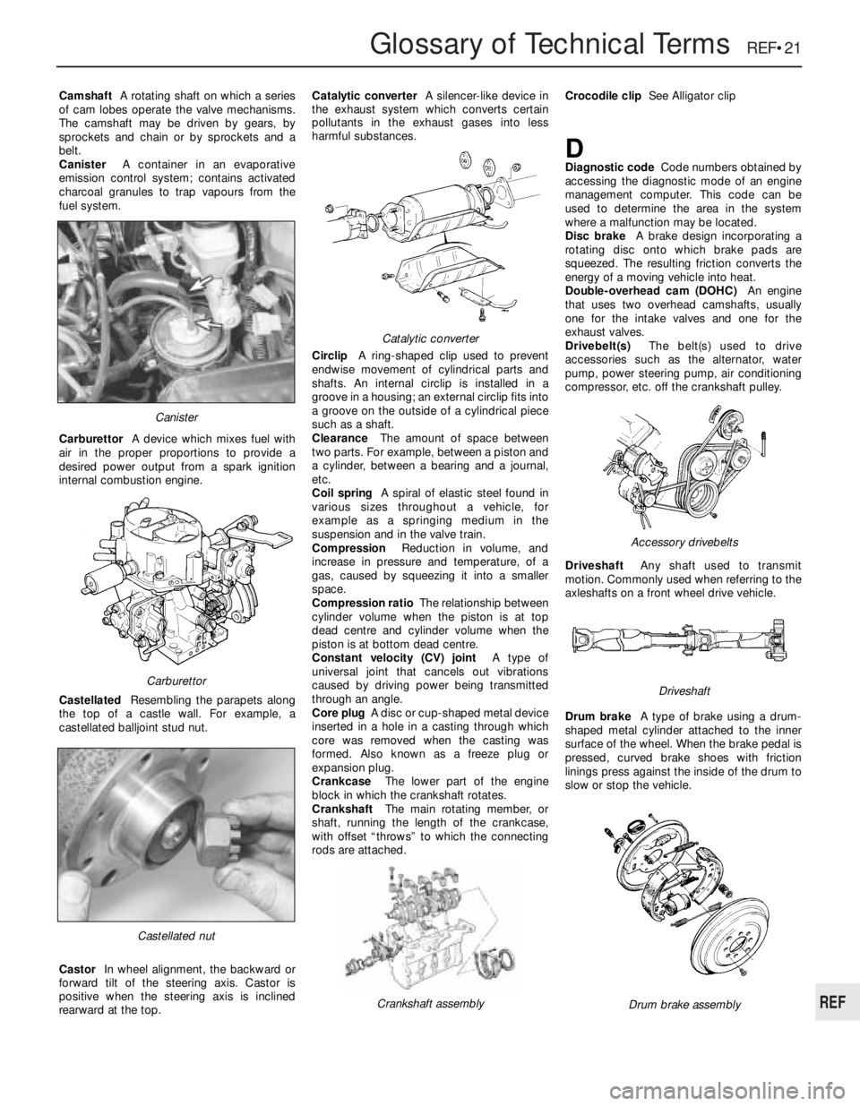
CamshaftA rotating shaft on which a series
of cam lobes operate the valve mechanisms.
The camshaft may be driven by gears, by
sprockets and chain or by sprockets and a
belt.
CanisterA container in an evaporative
emission control system; contains activated
charcoal granules to trap vapours from the
fuel system.
CarburettorA device which mixes fuel with
air in the proper proportions to provide a
desired power output from a spark ignition
internal combustion engine.
CastellatedResembling the parapets along
the top of a castle wall. For example, a
castellated balljoint stud nut.
CastorIn wheel alignment, the backward or
forward tilt of the steering axis. Castor is
positive when the steering axis is inclined
rearward at the top.Catalytic converterA silencer-like device in
the exhaust system which converts certain
pollutants in the exhaust gases into less
harmful substances.
CirclipA ring-shaped clip used to prevent
endwise movement of cylindrical parts and
shafts. An internal circlip is installed in a
groove in a housing; an external circlip fits into
a groove on the outside of a cylindrical piece
such as a shaft.
ClearanceThe amount of space between
two parts. For example, between a piston and
a cylinder, between a bearing and a journal,
etc.
Coil springA spiral of elastic steel found in
various sizes throughout a vehicle, for
example as a springing medium in the
suspension and in the valve train.
CompressionReduction in volume, and
increase in pressure and temperature, of a
gas, caused by squeezing it into a smaller
space.
Compression ratioThe relationship between
cylinder volume when the piston is at top
dead centre and cylinder volume when the
piston is at bottom dead centre.
Constant velocity (CV) jointA type of
universal joint that cancels out vibrations
caused by driving power being transmitted
through an angle.
Core plugA disc or cup-shaped metal device
inserted in a hole in a casting through which
core was removed when the casting was
formed. Also known as a freeze plug or
expansion plug.
CrankcaseThe lower part of the engine
block in which the crankshaft rotates.
CrankshaftThe main rotating member, or
shaft, running the length of the crankcase,
with offset “throws” to which the connecting
rods are attached.Crocodile clipSee Alligator clip
DDiagnostic codeCode numbers obtained by
accessing the diagnostic mode of an engine
management computer. This code can be
used to determine the area in the system
where a malfunction may be located.
Disc brakeA brake design incorporating a
rotating disc onto which brake pads are
squeezed. The resulting friction converts the
energy of a moving vehicle into heat.
Double-overhead cam (DOHC)An engine
that uses two overhead camshafts, usually
one for the intake valves and one for the
exhaust valves.
Drivebelt(s)The belt(s) used to drive
accessories such as the alternator, water
pump, power steering pump, air conditioning
compressor, etc. off the crankshaft pulley.
DriveshaftAny shaft used to transmit
motion. Commonly used when referring to the
axleshafts on a front wheel drive vehicle.
Drum brakeA type of brake using a drum-
shaped metal cylinder attached to the inner
surface of the wheel. When the brake pedal is
pressed, curved brake shoes with friction
linings press against the inside of the drum to
slow or stop the vehicle.
Castellated nut
Catalytic converter
Crankshaft assembly
Carburettor
Canister
Drum brake assembly
Accessory drivebelts
Driveshaft