spare tire OPEL VECTRA 1988 Service Repair Manual
[x] Cancel search | Manufacturer: OPEL, Model Year: 1988, Model line: VECTRA, Model: OPEL VECTRA 1988Pages: 525, PDF Size: 58.26 MB
Page 8 of 525

underside. If the distance measured exceeds,
or is less than, that specified, the float weight
is incorrect and the float must be renewed.
12When the float level is known to be
correct, reassemble the carburettor, using a
new top cover gasket. Check the idle speed
and mixture settings as described in Section
14.
13Using a pin punch, tap the float retaining
pin from the base of the top cover, and lift out
the float and needle valve.
14Inspect the components for damage, and
renew as necessary. Check the needle valve
for wear, and check the float for leaks by
shaking it to see if it contains petrol.
15Clean the mating faces of the carburettor
body and top cover.
Refitting
16Refitting is a reversal of removal,
remembering the following points.
17After refitting, check the float and needle
valve for full and free movement.
18Use a new gasket between the top cover
and the carburettor body.
19Ensure that all hoses, pipes and wires are
correctly reconnected.
20On completion, check and if necessary
top-up the coolant level, as described in
Chapter 3, and check and if necessary adjust
the idle speed and mixture, as described in
Section 14.
16Secondary throttle valve
vacuum diaphragm - testing,
removal and refitting
3
Note: The diaphragm unit must be renewed in
its entirety, as no spares are available
Testing
1If a vacuum source incorporating a gauge is
available, apply approximately 300 mbars (9 in
Hg) to the diaphragm unit, at the hose nearest
the carburettor body. Close off the vacuum
source, and check that the vacuum is held. If
there is a leak, rectify or renew the leaking
component. Alternately, testing of a suspect
vacuum unit must be by the substitution of a
known good item.
Removal
2Remove the air cleaner, on early models.
On later models, disconnect the air trunking
from the air cleaner, then disconnect the
vacuum pipe air breather hose from the air
box. Extract the three securing screws and lift
off the air box, complete with air trunking.
3Disconnect the vacuum pipe from the
diaphragm unit.
4Prise the diaphragm operating rod balljoint
from the secondary throttle valve linkage.
5On 1.6 and 1.8 litre models, remove the two
securing screws and lift the vapour separator
from the bracket. Move the vapour separator
to one side, taking care not to strain the fuel
hoses.6Remove the three securing screws, and
withdraw the diaphragm unit complete with its
bracket from the carburettor body.
Refitting
7Refitting is a reversal of removal.
17Power valve diaphragm -
removal and refitting
3
Note: Refer to Section 2 before proceeding
Removal
1Disconnect the battery negative lead.
2Remove the air cleaner, on early models.
On later models, disconnect the air trunking
from the air cleaner, then disconnect the
vacuum pipe and breather hose from the airbox. Extract the three securing screws and lift
off the air box, complete with air trunking.
3Thoroughly clean all external dirt from the
area around the power valve housing.
4Remove the two securing screws, and lift
off the power valve cover, spring, and
diaphragm assembly.
Refitting
5Clean the mating faces of the cover and
housing.
6Locate the spring on the cover and
diaphragm assembly, ensuring that it is
correctly seated, then press the diaphragm
assembly and cover together. Note that the
vacuum hole in the diaphragm must align with
the corresponding holes in the housing flange
and cover.
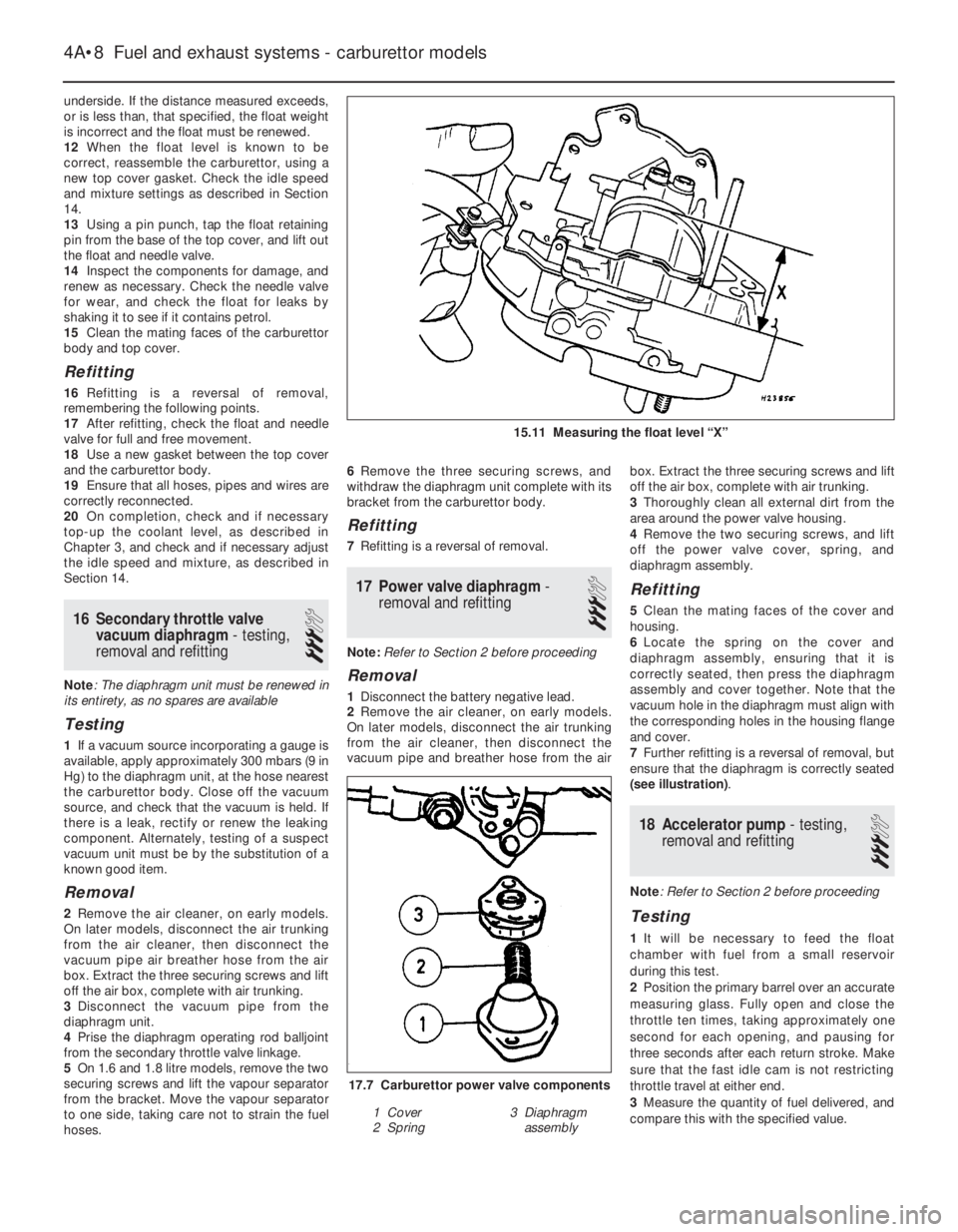
7Further refitting is a reversal of removal, but
ensure that the diaphragm is correctly seated
(see illustration).
18Accelerator pump - testing,
removal and refitting
3
Note: Refer to Section 2 before proceeding
Testing
1It will be necessary to feed the float
chamber with fuel from a small reservoir
during this test.
2Position the primary barrel over an accurate
measuring glass. Fully open and close the
throttle ten times, taking approximately one
second for each opening, and pausing for
three seconds after each return stroke. Make
sure that the fast idle cam is not restricting
throttle travel at either end.
3Measure the quantity of fuel delivered, and
compare this with the specified value.
4A•8Fuel and exhaust systems - carburettor models
15.11 Measuring the float level “X”
17.7 Carburettor power valve components
1 Cover
2 Spring3 Diaphragm
assembly