battery replacement OPEL VECTRA 1988 Service Repair Manual
[x] Cancel search | Manufacturer: OPEL, Model Year: 1988, Model line: VECTRA, Model: OPEL VECTRA 1988Pages: 525, PDF Size: 58.26 MB
Page 96 of 525
2When the starter switch is operated, current
flows from the battery to the solenoid that is
mounted on the starter body. The plunger in
the solenoid moves inwards, so causing a
centrally pivoted lever to push the drive pinion
into mesh with the starter ring gear. When the
solenoid plunger reaches the end of its travel,
it closes an internal contact and full starting
current flows to the starter field coils. The
armature is then able to rotate the crankshaft,
so starting the engine.
3A special freewheel clutch is fitted to the
starter driven pinion, so that when the engine
fires and starts to operate on its own it does
not drive the starter motor.
4When the starter switch is released, the
solenoid is de-energised, and a spring moves
the plunger back to its rest position. This
operates the pivoted lever to the withdraw the
drive pinion from engagement with the starter
ring.
13Starter motor - testing
3
Note: Refer to Section 3 before proceeding
Testing
1If the starter motor fails to turn the engine
when the switch is operated, and engine
seizure is not the problem, there are several
other possible reasons:
a)The battery is faulty
b)The electrical connections between the
switch, solenoid battery and starter motor
are somewhere failing to pass the
necessary current from the battery
through the starter to earth
c)The solenoid switch is faulty
d)The starter motor is mechanically or
electrically defective
e)The starter motor pinion and/or flywheel
ring gear is badly worn, and in need of
replacement
2To check the battery, switch on the
headlamps. If they dim after a few seconds,
then the battery is in a discharged state. If the
lamps glow brightly, operate the starter switch
and see what happens to the lamps. If theydim, then power is reaching the motor, but
failing to turn it. If the starter turns slowly, go
on to the next check.
3If, when the starter switch is operated, the
lamps stay bright, then insufficient power is
reaching the motor. Disconnect the battery
and the starter/solenoid power connections,
and the engine earth strap, then thoroughly
clean them and refit them. Smear petroleum
jelly around the battery connections to
prevent corrosion. Corroded connections are
the most frequent cause of electrical system
malfunctions.
4If the preceding checks and cleaning tasks
have been carried out without success, a
clicking noise will probably have been heard
each time the starter switch was operated.
This indicates that the solenoid switch was
operating, but it does not necessarily follow
that the main contacts were closing properly
(if no clicking has been heard from the
solenoid, it is certainly defective). The
solenoid can be checked by connecting a
voltmeter across the main cable connection
on the solenoid and earth. When the switch is
operated, these should be a reading on the
voltmeter. If there is no reading, the solenoid
unit is faulty, and should be renewed.
5If the starter motor operates, but does not
turn the engine, then it is likely that the starter
pinion and/or flywheel ring gear are badly
worn. If this is the case, the starter motor will
normally be noisy in operation.
6Finally, if it is established that the solenoid
is not faulty, and 12 volts are reaching the
starter, then the motor itself is faulty, and
should be removed for inspection.
14Starter motor - removal and
refitting
3
Note: Refer to Section 3 before proceeding
Removal
1Disconnect the battery negative lead.
2Apply the handbrake, then jack up the front
of the vehicle, and support securely on axle
stands (see “Jacking and Vehicle Support”)
positioned under the body side members.3On DOHC models, remove the engine
undershield, as described in Chapter 11.
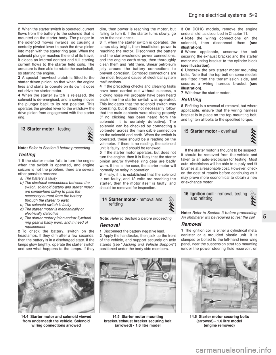
4Note the wiring connections on the
solenoid, then disconnect them (see
illustration).
5Where applicable, unscrew the bolt
securing the exhaust bracket and the starter
motor mounting bracket to the cylinder block
(see illustration).
6Unscrew the two starter motor mounting
bolts. Note that the top bolt on some models
are fitted from the transmission side, and
secures a wiring harness bracket (see
illustration).
7Withdraw the starter motor.
Refitting
8Refitting is a reversal of removal, but where
applicable, ensure that the wiring harness
bracket is in place on the top mounting bolt,
and tighten all bolts to the specified torque.
15Starter motor - overhaul
5
If the starter motor is thought to be suspect,
it should be removed from the vehicle and
taken to an auto-electrician for testing. Most
auto-electricians will be able to supply and fit
brushes at a reasonable cost. However, check
on the cost of repairs before continuing as it
may prove more economical to obtain a new
or exchange motor.
16Ignition coil - removal, testing
and refitting
3
Note: Refer to Section 3 before proceeding.
An ohmmeter will be required to test the coil
Removal
1The ignition coil is either a cylindrical metal
canister or a moulded plastic unit. It is
clamped or bolted to the left-hand inner wing
panel, near the suspension strut top mounting
(under the power steering fluid reservoir, on
Engine electrical systems 5•9
14.6 Starter motor securing bolts
(arrowed) - 1.6 litre model
(engine removed)14.5 Starter motor mounting
bracket/exhaust bracket securing bolt
(arrowed) - 1.6 litre model14.4 Starter motor and solenoid viewed
from underneath the vehicle. Solenoid
wiring connections arrowed
5
Page 99 of 525
been removed, check that No 1 cylinder is on
its firing stroke by removing No 1 cylinder
spark plug and placing a finger over the plug
hole. Turn the crankshaft until compression
can be felt, which indicates that No 1 piston is
rising on its compression stroke. Continue
turning the crankshaft until the relevant timing
marks are in alignment.
11Turn the rotor arm to the position noted in
paragraph 6c, and hold the rotor arm in this
position as the distributor is fitted. Note that
the distributor driveshaft will only engage with
the camshaft in one position. If the original
distributor is being refitted, align the marks
made on the distributor body and camshaft
housing before removal.
12Refit the clamp plate and nut, but do not
fully tighten the nut at this stage.
13On the Bosch distributor, remove the rotor
arm, then refit the plastic shield and the rotor
arm.
14On 14 NV models, reconnect the vacuum
pipe to the diaphragm unit.
15Reconnect the distributor wiring plug.
16Refit the distributor cap as described in
Section 17.
17Reconnect the battery negative lead.
18Check and if necessary adjust the ignition
timing, as described in Section 21.
19Distributor (DOHC models),
where applicable - removal
and refitting
3
Removal
1Disconnect the battery negative lead.
2Remove the distributor cap, as described in
Section 17.
3Disconnect the distributor wiring plug.
4Unscrew the two securing bolts, and
remove the distributor from the cylinder head.
5Examine the O-ring on the rear of the
distributor, and renew if necessary.
Refitting
6Refitting is a reversal of removal. However,
note that the distributor should be fitted so
that the wiring plug is positioned on the upper
left-hand side of the distributor body, when
viewed from the distributor cap end.
20Distributor - dismantling,
inspection and reassembly
3
Note: Before contemplating dismantling of a
distributor, check the cost and availability of
replacement parts. It may prove more
economical to renew the complete distributor
assembly
14 NV models
Dismantling
1With the distributor removed as described
in Section 18, continue as follows.
2Pull off the rotor arm, and remove the
plastic shield.
3The top bearing plate can be removed after
unscrewing the two securing screws, however
(other than the vacuum diaphragm unit), no
spares are available for the distributor and no
adjustments are required.
4If desired, the vacuum diaphragm unit can
be removed by extracting the two securing
screws and unhooking the operating arm from
the distributor baseplate. Note that the
screws are of differing lengths, the longer
screw also secures one of the distributor cap
clips.
Inspection
5The vacuum unit can be tested by applying
suction to the vacuum port, and checking that
the operating rod moves into the unit as
suction is applied. Remove the suction, and
check that the operating rod returns to its
original position. If the operating rod does not
move as described, renew the vacuum unit.
6Check the distributor cap for corrosion of
the segments, and for signs of tracking,
indicated by a thin black line between the
segments. Make sure that the carbon brush in
the centre of the cap moves freely and stands
proud of the surface of the cap. Renew the
cap if necessary.
7If the metal portion of the rotor arm is badly
burnt or loose, renew it. If slightly burnt or
corroded; it may be cleaned with a fine file.
8Examine the seal ring at the rear of the
distributor body, and renew if necessary.
Reassembly
9Reassembly is a reversal of dismantling,
ensuring that the vacuum unit operating arm
is correctly engaged with the peg on the
baseplate, several attempts may be required
to reconnect it.
10Refit the distributor as described in
Section 18, and then check and if necessary
adjust the ignition timing, as described in
Section 21.
16 SV models
Dismantling
11With the distributor removed as described
in Section 18, pull off the rotor arm and, on
the Bosch distributor, remove the plastic
shield.
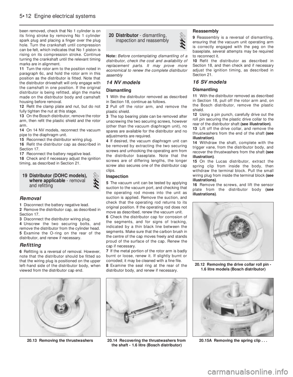
12Using a pin punch, carefully drive out the
roll pin securing the plastic drive collar to the
rear of the distributor shaft (see illustration).
13Lift off the drive collar, and remove the
thrustwashers from the end of the shaft (see
illustration).
14Withdraw the shaft, complete with the
trigger vane, from the distributor body, and
recover the thrustwashers from the shaft (see
illustration).
15On the Lucas distributor, extract the
spring clip from inside the body, then
withdraw the terminal block. Pull the small
wiring plug from inside the terminal block (see
illustrations).
16Remove the screws, and lift the sensor
plate from the distributor body (see
illustrations).
5•12Engine electrical systems
20.15A Removing the spring clip . . .20.14 Recovering the thrustwashers from
the shaft - 1.6 litre (Bosch distributor)20.13 Removing the thrustwashers
20.12 Removing the drive collar roll pin -
1.6 litre models (Bosch distributor)
Page 144 of 525
14Front brake disc shield -
removal and refitting
3
Removal
1Where applicable, remove the wheel trim,
then loosen the relevant front roadwheel bolts
and apply the handbrake. Jack up the front of
the vehicle, and support on axle stands (see
“Jacking and Vehicle Support”) positioned
under the body side members. Remove the
roadwheel.
2Remove the brake disc, as described in
Section 10.
3Using a screwdriver inserted through the
holes in the hub flange, extract the three
screws securing the disc shield to the hub
carrier.
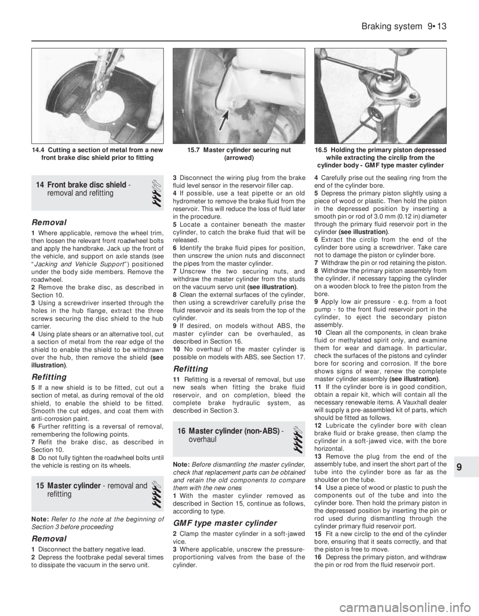
4Using plate shears or an alternative tool, cut
a section of metal from the rear edge of the
shield to enable the shield to be withdrawn
over the hub, then remove the shield (see
illustration).
Refitting
5If a new shield is to be fitted, cut out a
section of metal, as during removal of the old
shield, to enable the shield to be fitted.
Smooth the cut edges, and coat them with
anti-corrosion paint.
6Further refitting is a reversal of removal,
remembering the following points.
7Refit the brake disc, as described in
Section 10.
8Do not fully tighten the roadwheel bolts until
the vehicle is resting on its wheels.
15Master cylinder - removal and
refitting
4
Note: Refer to the note at the beginning of
Section 3 before proceeding
Removal
1Disconnect the battery negative lead.
2Depress the footbrake pedal several times
to dissipate the vacuum in the servo unit.3Disconnect the wiring plug from the brake
fluid level sensor in the reservoir filler cap.
4If possible, use a teat pipette or an old
hydrometer to remove the brake fluid from the
reservoir. This will reduce the loss of fluid later
in the procedure.
5Locate a container beneath the master
cylinder, to catch the brake fluid that will be
released.
6Identify the brake fluid pipes for position,
then unscrew the union nuts and disconnect
the pipes from the master cylinder.
7Unscrew the two securing nuts, and
withdraw the master cylinder from the studs
on the vacuum servo unit (see illustration).
8Clean the external surfaces of the cylinder,
then using a screwdriver carefully prise the
fluid reservoir and its seals from the top of the
cylinder.
9If desired, on models without ABS, the
master cylinder can be overhauled, as
described in Section 16.
10No overhaul of the master cylinder is
possible on models with ABS, see Section 17.
Refitting
11Refitting is a reversal of removal, but use
new seals when fitting the brake fluid
reservoir, and on completion, bleed the
complete brake hydraulic system, as
described in Section 3.
16Master cylinder (non-ABS) -
overhaul
4
Note: Before dismantling the master cylinder,
check that replacement parts can be obtained
and retain the old components to compare
them with the new ones
1With the master cylinder removed as
described in Section 15, continue as follows,
according to type.
GMF type master cylinder
2Clamp the master cylinder in a soft-jawed
vice.
3Where applicable, unscrew the pressure-
proportioning valves from the base of the
cylinder.4Carefully prise out the sealing ring from the
end of the cylinder bore.
5Depress the primary piston slightly using a
piece of wood or plastic. Then hold the piston
in the depressed position by inserting a
smooth pin or rod of 3.0 mm (0.12 in) diameter
through the primary fluid reservoir port in the
cylinder (see illustration).
6Extract the circlip from the end of the
cylinder bore using a screwdriver. Take care
not to damage the piston or cylinder bore.
7Withdraw the pin or rod retaining the piston.
8Withdraw the primary piston assembly from
the cylinder, if necessary tapping the cylinder
on a wooden block to free the piston from the
bore.
9Apply low air pressure - e.g. from a foot
pump - to the front fluid reservoir port in the
cylinder, to eject the secondary piston
assembly.
10Clean all the components, in clean brake
fluid or methylated spirit only, and examine
them for wear and damage. In particular,
check the surfaces of the pistons and cylinder
bore for scoring and corrosion. If the bore
shows signs of wear, renew the complete
master cylinder assembly (see illustration).
11If the cylinder bore is in good condition,
obtain a repair kit, which will contain all the
necessary renewable items. A Vauxhall dealer
will supply a pre-assembled kit of parts, which
should be fitted as follows.
12Lubricate the cylinder bore with clean
brake fluid or brake grease, then clamp the
cylinder in a soft-jawed vice, with the bore
horizontal.
13Remove the plug from the end of the
assembly tube, and insert the short part of the
tube into the cylinder bore as far as the
shoulder on the tube.
14Use a piece of wood or plastic to push the
components out of the tube and into the
cylinder bore. Then hold the primary piston in
the depressed position by inserting the pin or
rod used during dismantling through the
cylinder primary fluid reservoir port.
15Fit a new circlip to the end of the cylinder
bore, ensuring that it seats correctly, and that
the piston is free to move.
16Depress the primary piston, and withdraw
the pin or rod from the fluid reservoir port.
Braking system 9•13
16.5 Holding the primary piston depressed
while extracting the circlip from the
cylinder body - GMF type master cylinder15.7 Master cylinder securing nut
(arrowed)14.4 Cutting a section of metal from a new
front brake disc shield prior to fitting
9
Page 172 of 525
1
Chapter 1
Routine maintenance and servicing
Air cleaner element - renewal . . . . . . . . . . . . . . . . . . . . . . . . . . . . . . .27
Air inlet temperature control check . . . . . . . . . . . . . . . . . . . . . . . . . .28
Alternator V-belt check . . . . . . . . . . . . . . . . . . . . . . . . . . . . . . . . . . . .22
Automatic transmission check . . . . . . . . . . . . . . . . . . . . . . . . . . . . . .34
Automatic transmission fluid level check . . . . . . . . . . . . . . . . . . . . . . .7
Automatic transmission fluid renewal . . . . . . . . . . . . . . . . . . . . . . . . .38
Bodywork check . . . . . . . . . . . . . . . . . . . . . . . . . . . . . . . . . . . . . . . . .20
Brake fluid renewal . . . . . . . . . . . . . . . . . . . . . . . . . . . . . . . . . . . . . . .14
Brake pad check . . . . . . . . . . . . . . . . . . . . . . . . . . . . . . . . . . . . . . . . .15
Brake shoe check . . . . . . . . . . . . . . . . . . . . . . . . . . . . . . . . . . . . . . . .35
Clutch cable check . . . . . . . . . . . . . . . . . . . . . . . . . . . . . . . . . . . . . . .32
Coolant renewal . . . . . . . . . . . . . . . . . . . . . . . . . . . . . . . . . . . . . . . . .26
Distributor and HT lead check . . . . . . . . . . . . . . . . . . . . . . . . . . . . . .31
Door lock key battery - replacement . . . . . . . . . . . . . . . . . . . . . . . . .24
Driveshaft gaiter check . . . . . . . . . . . . . . . . . . . . . . . . . . . . . . . . . . . . .6
Engine oil and filter - renewal . . . . . . . . . . . . . . . . . . . . . . . . . . . . . . . .3
Exhaust system check . . . . . . . . . . . . . . . . . . . . . . . . . . . . . . . . . . . .11
Fuel filter renewal . . . . . . . . . . . . . . . . . . . . . . . . . . . . . . . . . . . . . . . .29
Handbrake linkage check . . . . . . . . . . . . . . . . . . . . . . . . . . . . . . . . . .16Headlamp alignment . . . . . . . . . . . . . . . . . . . . . . . . . . . . . . . . . . . . . .23
Hose and fluid leak check . . . . . . . . . . . . . . . . . . . . . . . . . . . . . . . . . .4
Idle speed and mixture - adjustment . . . . . . . . . . . . . . . . . . . . . . . . . .9
Ignition timing . . . . . . . . . . . . . . . . . . . . . . . . . . . . . . . . . . . . . . . . . . .13
Intensive maintenance . . . . . . . . . . . . . . . . . . . . . . . . . . . . . . . . . . . . .2
Introduction . . . . . . . . . . . . . . . . . . . . . . . . . . . . . . . . . . . . . . . . . . . . .1
Lock and hinge check . . . . . . . . . . . . . . . . . . . . . . . . . . . . . . . . . . . .21
Manual transmission fluid check . . . . . . . . . . . . . . . . . . . . . . . . . . . .33
Power steering fluid check . . . . . . . . . . . . . . . . . . . . . . . . . . . . . . . . .17
Power steering pump drivebelt check . . . . . . . . . . . . . . . . . . . . . . . .18
Radiator inspection and cleaning . . . . . . . . . . . . . . . . . . . . . . . . . . . . .8
Rear suspension level control system check . . . . . . . . . . . . . . . . . . .19
Road test . . . . . . . . . . . . . . . . . . . . . . . . . . . . . . . . . . . . . . . . . . . . . .25
Spark plug renewal (SOHC) . . . . . . . . . . . . . . . . . . . . . . . . . . . . . . . .30
Spark plug renewal (DOHC) . . . . . . . . . . . . . . . . . . . . . . . . . . . . . . . .37
Steering and suspension check . . . . . . . . . . . . . . . . . . . . . . . . . . . . . .5
Throttle linkage maintenance . . . . . . . . . . . . . . . . . . . . . . . . . . . . . . .10
Timing belt renewal . . . . . . . . . . . . . . . . . . . . . . . . . . . . . . . . . . . . . . .36
Wiring check . . . . . . . . . . . . . . . . . . . . . . . . . . . . . . . . . . . . . . . . . . . .12
1•1
Contents
Easy,suitable for
novice with little
experienceFairly easy,suitable
for beginner with
some experienceFairly difficult,
suitable for competent
DIY mechanic
Difficult,suitable for
experienced DIY
mechanicVery difficult,
suitable for expert DIY
or professional
Degrees of difficulty
54321
Page 184 of 525
tighten the mounting nuts and bolts. On no
account lever at the free end of the alternator,
as serious internal damage could be caused.
3For details of replacement, see Chapter 5.
23Headlamp alignment
2
Refer to Chapter 12 for details.
24Door lock key battery -
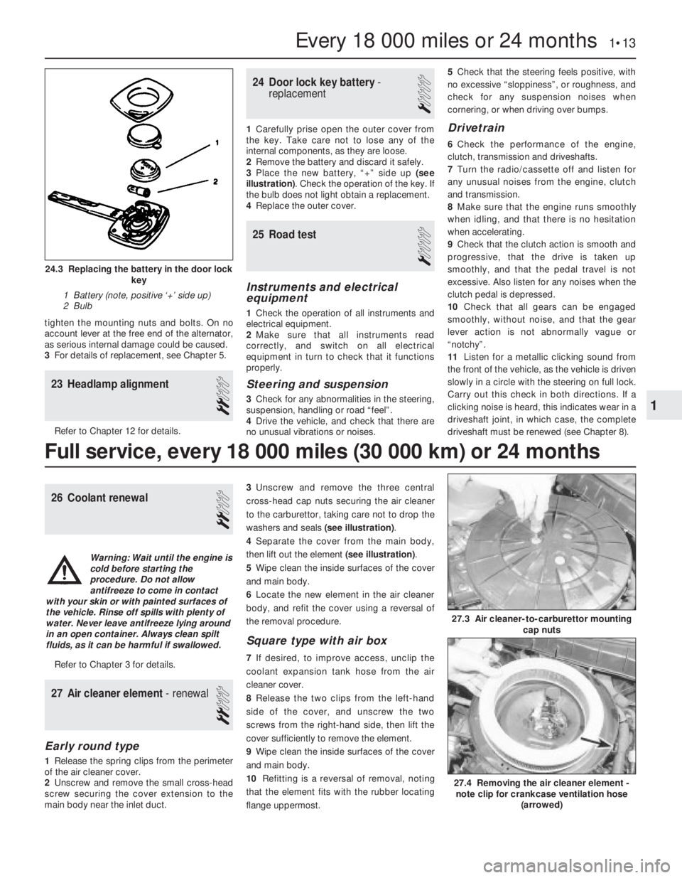
replacement
1
1Carefully prise open the outer cover from
the key. Take care not to lose any of the
internal components, as they are loose.
2Remove the battery and discard it safely.
3Place the new battery, “+” side up (see
illustration). Check the operation of the key. If
the bulb does not light obtain a replacement.
4Replace the outer cover.
25Road test
1
Instruments and electrical
equipment
1Check the operation of all instruments and
electrical equipment.
2Make sure that all instruments read
correctly, and switch on all electrical
equipment in turn to check that it functions
properly.
Steering and suspension
3Check for any abnormalities in the steering,
suspension, handling or road “feel”.
4Drive the vehicle, and check that there are
no unusual vibrations or noises.5Check that the steering feels positive, with
no excessive “sloppiness”, or roughness, and
check for any suspension noises when
cornering, or when driving over bumps.
Drivetrain
6Check the performance of the engine,
clutch, transmission and driveshafts.
7Turn the radio/cassette off and listen for
any unusual noises from the engine, clutch
and transmission.
8Make sure that the engine runs smoothly
when idling, and that there is no hesitation
when accelerating.
9Check that the clutch action is smooth and
progressive, that the drive is taken up
smoothly, and that the pedal travel is not
excessive. Also listen for any noises when the
clutch pedal is depressed.
10Check that all gears can be engaged
smoothly, without noise, and that the gear
lever action is not abnormally vague or
“notchy”.
11Listen for a metallic clicking sound from
the front of the vehicle, as the vehicle is driven
slowly in a circle with the steering on full lock.
Carry out this check in both directions. If a
clicking noise is heard, this indicates wear in a
driveshaft joint, in which case, the complete
driveshaft must be renewed (see Chapter 8).
26Coolant renewal
2
Refer to Chapter 3 for details.
27Air cleaner element - renewal
2
Early round type
1Release the spring clips from the perimeter
of the air cleaner cover.
2Unscrew and remove the small cross-head
screw securing the cover extension to the
main body near the inlet duct.3Unscrew and remove the three central
cross-head cap nuts securing the air cleaner
to the carburettor, taking care not to drop the
washers and seals (see illustration).
4Separate the cover from the main body,
then lift out the element (see illustration).
5Wipe clean the inside surfaces of the cover
and main body.
6Locate the new element in the air cleaner
body, and refit the cover using a reversal of
the removal procedure.
Square type with air box
7If desired, to improve access, unclip the
coolant expansion tank hose from the air
cleaner cover.
8Release the two clips from the left-hand
side of the cover, and unscrew the two
screws from the right-hand side, then lift the
cover sufficiently to remove the element.
9Wipe clean the inside surfaces of the cover
and main body.
10Refitting is a reversal of removal, noting
that the element fits with the rubber locating
flange uppermost.
Every 18 000 miles or 24 months 1•13
24.3 Replacing the battery in the door lock
key
1 Battery (note, positive ‘+’ side up)
2 Bulb
27.4 Removing the air cleaner element -
note clip for crankcase ventilation hose
(arrowed)
27.3 Air cleaner-to-carburettor mounting
cap nuts
1
Full service, every 18 000 miles (30 000 km) or 24 months
Warning: Wait until the engine is
cold before starting the
procedure. Do not allow
antifreeze to come in contact
with your skin or with painted surfaces of
the vehicle. Rinse off spills with plenty of
water. Never leave antifreeze lying around
in an open container. Always clean spilt
fluids, as it can be harmful if swallowed.
Page 190 of 525
Torque wrench settings (continued)Nmlbf ft
Starter to cylinder block . . . . . . . . . . . . . . . . . . . . . . . . . . . . . . . . . . . . .4533
Starter support to cylinder block . . . . . . . . . . . . . . . . . . . . . . . . . . . . . .2518
Temperature regulator plug (M20) * . . . . . . . . . . . . . . . . . . . . . . . . . . . .3022
Timing belt cover . . . . . . . . . . . . . . . . . . . . . . . . . . . . . . . . . . . . . . . . . .86
Timing belt drive gear to crankshaft: *
Stage 1 . . . . . . . . . . . . . . . . . . . . . . . . . . . . . . . . . . . . . . . . . . . . . . . .250184
Stage 2 . . . . . . . . . . . . . . . . . . . . . . . . . . . . . . . . . . . . . . . . . . . . . . . .Angle tighten by between 40°and 50°
Timing belt guide roller bracket to block . . . . . . . . . . . . . . . . . . . . . . . .2518
Timing belt guide roller to bracket . . . . . . . . . . . . . . . . . . . . . . . . . . . . .2518
Timing belt guide roller to cylinder block:
Engines up to 1993
Stage 1 . . . . . . . . . . . . . . . . . . . . . . . . . . . . . . . . . . . . . . . . . . . . . .2518
Stage 2 . . . . . . . . . . . . . . . . . . . . . . . . . . . . . . . . . . . . . . . . . . . . . .Angle tighten by 45°
Stage 3 . . . . . . . . . . . . . . . . . . . . . . . . . . . . . . . . . . . . . . . . . . . . . .Angle tighten by 15°
1993-on engines . . . . . . . . . . . . . . . . . . . . . . . . . . . . . . . . . . . . . . . . .2518
Transfer box bracket to cylinder block . . . . . . . . . . . . . . . . . . . . . . . . . .6044
Transmission to cylinder block . . . . . . . . . . . . . . . . . . . . . . . . . . . . . . . .6044
1General
This part of Chapter 2 describes
procedures that are specific to the DOHC
engine. It should be read in conjunction with
Part A.
The lower engine is basically the same as
the 2.0 litre SOHC. However the pistons are
attached to the connecting rods by gudgeon
pins, which are fully floating, and are secured
by circlips.
Both camshafts on these engines are driven
from the crankshaft by one toothed
composite rubber belt. Each cylinder has four
valves (two inlet and two exhaust), operated
directly from the camshafts by hydraulic
self-adjusting valve lifters. One camshaft
operates the inlet valves, and the other
operates the exhaust valves.
DOHC models are fitted with a remotely
mounted oil cooler.
The distributor is driven directly from the
exhaust camshaft.
2Engine - removal and refitting
4
Removal
1Carry out procedure in Chapter 2A, noting
the following differences.
2With the car safely raised, remove the
engine undershield.
3The fuel hoses need to be disconnected
from the fuel rail.
4Disconnect coolant hoses from the cylinder
block and cylinder head. Also disconnect the
oil cooler pipe unions from the oil pump.
5Unbolt the right-hand driveshaft centre
bearing support bracket from the rear of the
cylinder block.
Refitting
6Refitting the engine is similar to theprocedure in Chapter 2A. The exceptions
being, replacement of the right-hand
driveshaft centre bearing support bracket at
the rear of the cylinder block and retightening
the securing bolts.
7Replace the undershield.
3Engine/transmission
mountings- renewal
3
The procedure for replacing the engine/
transmission is similar to SOHC models, see
Chapter 2A. However this engine is fitted with
an undershield that needs to be removed
before replacing the mounts. Do not forget to
replace the undershield before lowering the
car.
4Timing belt, sprockets and belt
tensioner and idler pulleys-
removal, refitting and adjustment
3
Note: The timing belt should be renewed on
refitting. A two-legged puller may be required
to remove the crankshaft sprocket
Removal
1Disconnect the battery negative lead.2Disconnect the air cleaner trunking from the
airflow meter, then remove the cover and the
air cleaner element from the air cleaner. If
desired, for improved access, the complete
air cleaner assembly can be removed, as
described in Chapter 4B.
3Remove the power steering pump drivebelt,
as described in Chapter 10.
4Remove the alternator drivebelt, as
described in Chapter 5.
5Remove the three securing screws, and
withdraw the outer timing belt cover. Recover
the rubber grommets from the screw holes in
the cover if they are loose.
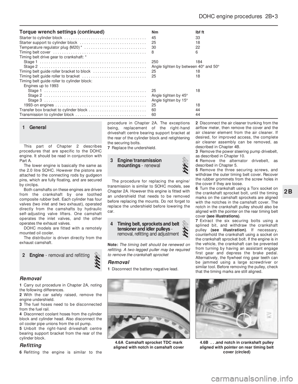
6Turn the crankshaft using a Torx socket on
the crankshaft sprocket bolt, until the timing
marks on the camshaft sprockets are aligned
with the notches in the camshaft cover. The
notch in the crankshaft pulley should also be
aligned with the pointer on the rear timing belt
cover (see illustrations).
7Extract the six securing bolts using a
splined bit, and withdraw the crankshaft
pulley (see illustration). If necessary,
counterhold the crankshaft using a socket on
the crankshaft sprocket bolt. If the engine is in
the vehicle, the crankshaft can be prevented
from turning by having an assistant engage
first gear and depress the brake pedal.
Alternatively, the flywheel ring gear teeth can
be jammed using a large screwdriver or
similar tool. Before removing the pulley, check
that the timing marks are still aligned.
DOHC engine procedures 2B•3
4.6B . . .and notch in crankshaft pulley
aligned with pointer on rear timing belt
cover (circled)4.6A Camshaft sprocket TDC mark
aligned with notch in camshaft cover
2B
Page 216 of 525
Inspection
7With the camshaft removed, examine the
bearings in the camshaft housing for signs of
obvious wear or pitting. If evident, a new
camshaft housing will probably be required.
8The camshaft itself should show no marks
or scoring on the journal or cam lobe
surfaces. If evident, renew the camshaft. Note
that if the camshaft is renewed, all the rocker
arms should also be renewed.
9Check the camshaft thrustplate for signs of
wear or grooves, and renew if evident.
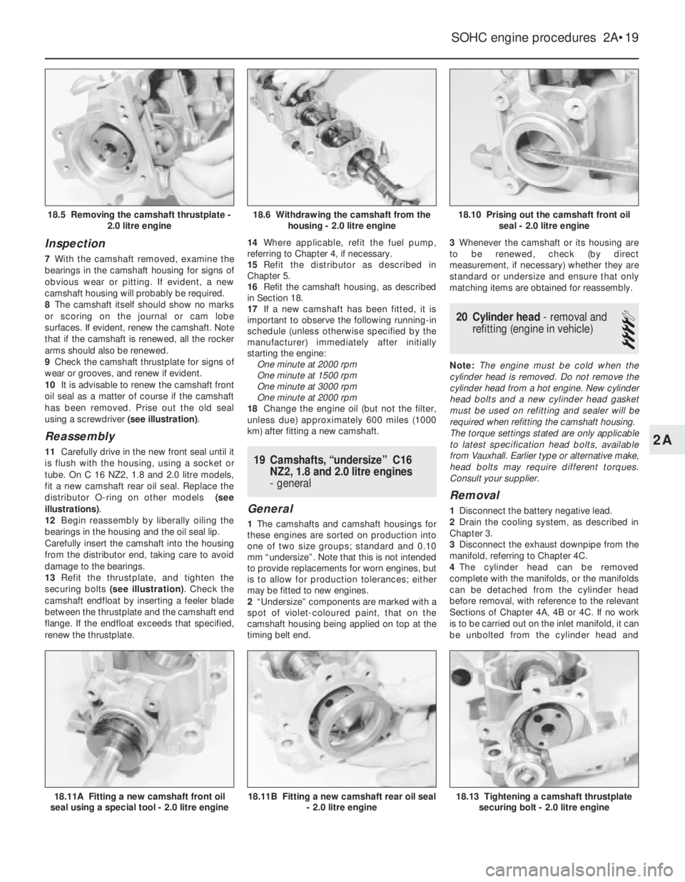
10It is advisable to renew the camshaft front
oil seal as a matter of course if the camshaft
has been removed. Prise out the old seal
using a screwdriver (see illustration).
Reassembly
11Carefully drive in the new front seal until it
is flush with the housing, using a socket or
tube. On C 16 NZ2, 1.8 and 2.0 litre models,
fit a new camshaft rear oil seal. Replace the
distributor O-ring on other models (see
illustrations).
12Begin reassembly by liberally oiling the
bearings in the housing and the oil seal lip.
Carefully insert the camshaft into the housing
from the distributor end, taking care to avoid
damage to the bearings.
13Refit the thrustplate, and tighten the
securing bolts (see illustration). Check the
camshaft endfloat by inserting a feeler blade
between the thrustplate and the camshaft end
flange. If the endfloat exceeds that specified,
renew the thrustplate.14Where applicable, refit the fuel pump,
referring to Chapter 4, if necessary.
15Refit the distributor as described in
Chapter 5.
16Refit the camshaft housing, as described
in Section 18.
17If a new camshaft has been fitted, it is
important to observe the following running-in
schedule (unless otherwise specified by the
manufacturer) immediately after initially
starting the engine:
One minute at 2000 rpm
One minute at 1500 rpm
One minute at 3000 rpm
One minute at 2000 rpm
18Change the engine oil (but not the filter,
unless due) approximately 600 miles (1000
km) after fitting a new camshaft.19Camshafts, “undersize” C16
NZ2, 1.8 and 2.0 litre engines
- general
General
1The camshafts and camshaft housings for
these engines are sorted on production into
one of two size groups; standard and 0.10
mm “undersize”. Note that this is not intended
to provide replacements for worn engines, but
is to allow for production tolerances; either
may be fitted to new engines.
2“Undersize” components are marked with a
spot of violet-coloured paint, that on the
camshaft housing being applied on top at the
timing belt end.3Whenever the camshaft or its housing are
to be renewed, check (by direct
measurement, if necessary) whether they are
standard or undersize and ensure that only
matching items are obtained for reassembly.
20Cylinder head - removal and
refitting (engine in vehicle)
4
Note: The engine must be cold when the
cylinder head is removed. Do not remove the
cylinder head from a hot engine. New cylinder
head bolts and a new cylinder head gasket
must be used on refitting and sealer will be
required when refitting the camshaft housing.
The torque settings stated are only applicable
to latest specification head bolts, available
from Vauxhall. Earlier type or alternative make,
head bolts may require different torques.
Consult your supplier.
Removal
1Disconnect the battery negative lead.
2Drain the cooling system, as described in
Chapter 3.
3Disconnect the exhaust downpipe from the
manifold, referring to Chapter 4C.
4The cylinder head can be removed
complete with the manifolds, or the manifolds
can be detached from the cylinder head
before removal, with reference to the relevant
Sections of Chapter 4A, 4B or 4C. If no work
is to be carried out on the inlet manifold, it can
be unbolted from the cylinder head and
SOHC engine procedures 2A•19
18.10 Prising out the camshaft front oil
seal - 2.0 litre engine
18.13 Tightening a camshaft thrustplate
securing bolt - 2.0 litre engine18.11B Fitting a new camshaft rear oil seal
- 2.0 litre engine18.11A Fitting a new camshaft front oil
seal using a special tool - 2.0 litre engine
18.6 Withdrawing the camshaft from the
housing - 2.0 litre engine18.5 Removing the camshaft thrustplate -
2.0 litre engine
2A
Page 251 of 525
Engine
m mEngine fails to rotate when attempting to start
m mEngine rotates, but will not start
m mEngine difficult to start when cold
m mEngine difficult to start when hot
m mStarter motor noisy or excessively rough in engagement
m mEngine starts, but stops immediately
m mEngine idles erratically
m mEngine misfires at idle speed
m mEngine misfires throughout the driving speed range
m mEngine hesitates on acceleration
m mEngine stalls
m mEngine lacks power
m mEngine backfires
m mOil pressure warning light illuminated with engine running
m mEngine runs-on after switching off
m mEngine noises
Cooling system
m
mOverheating
m mOvercooling
m mExternal coolant leakage
m mInternal coolant leakage
m mCorrosion
Fuel and exhaust systems
m
mExcessive fuel consumption
m mFuel leakage and/or fuel odour
m mExcessive noise or fumes from exhaust system
Clutch
m
mPedal travels to floor - no pressure or very little resistance
m mClutch fails to disengage (unable to select gears)
m mClutch slips (engine speed increases, with no increase in vehicle
speed)
m mJudder as clutch is engaged
m mNoise when depressing or releasing clutch pedal
Manual transmission
m
mNoisy in neutral with engine running
m mNoisy in one particular gear
m mDifficulty engaging gears
m mJumps out of gear
m mVibration
m mLubricant leaks
Automatic transmission
m
mFluid leakage
m mTransmission fluid brown, or has burned smell
m mGeneral gear selection problems
m mTransmission will not downshift (kickdown) with accelerator fully
depressed
m mEngine will not start in any gear, or starts in gears other than Park
or Neutral
m mTransmission slips, shifts roughly, is noisy, or has no drive in
forward or reverse gears
Driveshafts
m mClicking or knocking noise on turns (at slow speed on full-lock)
m mVibration when accelerating or decelerating
Braking system
m
mVehicle pulls to one side under braking
m mNoise (grinding or high-pitched squeal) when brakes applied
m mExcessive brake pedal travel
m mBrake pedal feels spongy when depressed
m mExcessive brake pedal effort required to stop vehicle
m mJudder felt through brake pedal or steering wheel when braking
m mBrakes binding
m mRear wheels locking under normal braking
Suspension and steering systems
m
mVehicle pulls to one side
m mWheel wobble and vibration
m mExcessive pitching and/or rolling around corners, or during
braking
m mWandering or general instability
m mExcessively stiff steering
m mExcessive play in steering
m mLack of power assistance
m mTyre wear excessive
Electrical system
m
mBattery will not hold a charge for more than a few days
m mIgnition/no-charge warning light remains illuminated with engine
running
m mIgnition/no-charge warning light fails to come on
m mLights inoperative
m mInstrument readings inaccurate or erratic
m mHorn inoperative, or unsatisfactory in operation
m mWindscreen/tailgate wipers inoperative, or unsatisfactory in
operation
m mWindscreen/tailgate washers inoperative, or unsatisfactory in
operation
m mElectric windows inoperative, or unsatisfactory in operation
m mCentral locking system inoperative, or unsatisfactory in operation
The vehicle owner who does his or her own maintenance according to
the recommended service schedules should not have to use this section
of the manual very often. Modern component reliability is such that,
provided those items subject to wear or deterioration are inspected or
renewed at the specified intervals, sudden failure is comparatively rare.
Faults do not usually just happen as a result of sudden failure, but
develop over a period of time. Major mechanical failures in particular are
usually preceded by characteristic symptoms over hundreds or even
thousands of miles. Those components that do occasionally fail without
warning are often small and easily carried in the vehicle.
With any fault-finding, the first step is to decide where to begininvestigations. Sometimes this is obvious, but on other occasions, a
little detective work will be necessary. The owner who makes half a
dozen haphazard adjustments or replacements may be successful in
curing a fault (or its symptoms). However, will be none the wiser if the
fault recurs, and ultimately may have spent more time and money than
was necessary. A calm and logical approach will be found to be more
satisfactory in the long run. Always take into account any warning
signs or abnormalities that may have been noticed in the period
preceding the fault - power loss, high or low gauge readings, unusual
smells, etc. - and remember that failure of components such as fuses
or spark plugs may only be pointers to some underlying fault.
REF•12Fault Finding
Introduction