OPEL VIVARO B 2018 Manual user
Manufacturer: OPEL, Model Year: 2018, Model line: VIVARO B, Model: OPEL VIVARO B 2018Pages: 237, PDF Size: 5.57 MB
Page 181 of 237
Vehicle care1795.Push to install the bulb holder into
the lamp assembly, then rotate
clockwise to secure.
6. Reattach wiring connector to lamp
assembly.
7. Install lamp assembly with the two bolts.
Number plate light
H1 roof height
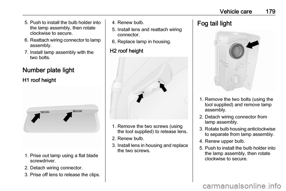
1. Prise out lamp using a flat blade screwdriver.
2. Detach wiring connector.
3. Prise off lens to release the clips.
4. Renew bulb.
5. Install lens and reattach wiring connector.
6. Replace lamp in housing.
H2 roof height
1. Remove the two screws (using the tool supplied) to release lens.
2. Renew bulb.
3. Install lens in housing and replace
the two screws.
Fog tail light
1. Remove the two bolts (using the tool supplied) and remove lamp
assembly.
2. Detach wiring connector from lamp assembly.
3. Rotate bulb housing anticlockwise
to separate from lamp assembly.
4. Renew upper bulb.
5. Push to install the bulb holder into
the lamp assembly, then rotate
clockwise to secure.
Page 182 of 237

180Vehicle care6.Reattach wiring connector to lamp
assembly.
7. Install lamp assembly with the two bolts.
Interior lights
Front and rear courtesy lights
1. Release lens assembly from the clips and the locator using a flat
blade screwdriver.
2. Renew bulb.
3. Install lens assembly.
Load compartment light
1. Release lens assembly from the clips using a flat blade
screwdriver.
2. Remove rear cover on lamp assembly.
3. Renew bulb.
4. Install rear cover and lamp assembly.
Glovebox light
1. Remove lens assembly using aflat blade screwdriver.
2. Renew bulb.
3. Install lens assembly.
Instrument panel illumination
Have bulbs replaced by a workshop.
Page 183 of 237
Vehicle care181Electrical system
Fuses Data on the replacement fuse must
match the data on the defective fuse.
There are two fuse boxes in the
vehicle:
● on the left-hand side of the instrument panel, behind the trim
panel
● in the engine compartment located next to the battery
Note
The engine compartment fuse box
should only be accessed by a
workshop.
Before replacing a fuse, turn off the
respective switch and the ignition.
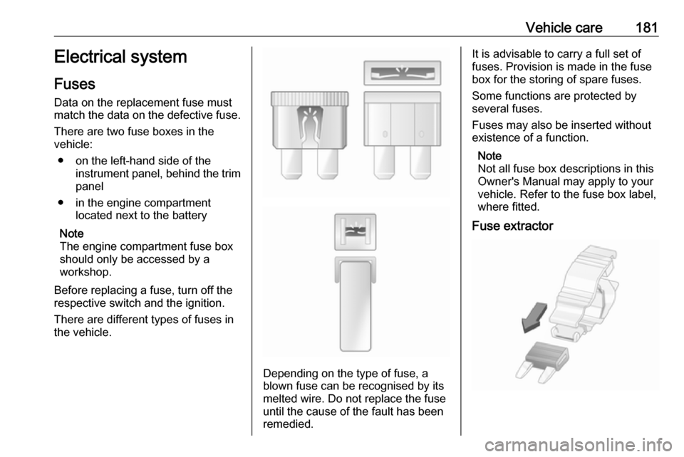
There are different types of fuses in
the vehicle.
Depending on the type of fuse, a
blown fuse can be recognised by its
melted wire. Do not replace the fuse until the cause of the fault has been
remedied.
It is advisable to carry a full set of
fuses. Provision is made in the fuse
box for the storing of spare fuses.
Some functions are protected by
several fuses.
Fuses may also be inserted without existence of a function.
Note
Not all fuse box descriptions in this
Owner's Manual may apply to your
vehicle. Refer to the fuse box label,
where fitted.
Fuse extractor
Page 184 of 237
182Vehicle care
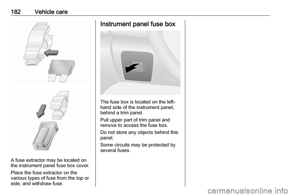
A fuse extractor may be located on
the instrument panel fuse box cover.
Place the fuse extractor on the
various types of fuse from the top or
side, and withdraw fuse.
Instrument panel fuse box
The fuse box is located on the left-
hand side of the instrument panel, behind a trim panel.
Pull upper part of trim panel and
remove to access the fuse box.
Do not store any objects behind this
panel.
Some circuits may be protected by
several fuses.
Page 185 of 237

Vehicle care183
Page 186 of 237

184Vehicle careNo.Circuit1Battery backup (with electronic
key system)2Adaptations3Adaptations4Vehicle battery (with electronic
key system)5Additional heating and ventila‐
tion / Air conditioning system6Supplementary heating and
ventilation system7Electric exterior mirrors / Addi‐
tional adaptations8Heated exterior mirrors9Radio / Multimedia / Electric
exterior mirrors / Diagnostic
socket10Multimedia / Trailer hitch11Courtesy lights / Battery
discharge protectionNo.Circuit12Right-hand high beam / Left-
hand low beam / Sidelights /
Right-hand daytime running
light13Hazard warning flashers / Turn
and lane-change signals14Central locking15Left-hand high beam / Right-
hand low beam / Tail lights /
Left-hand daytime running light16Front fog lights / Rear fog lights /
Number plate lighting17Alarm / Horn / Lighting / Wiper18Instrument cluster19Heating and ventilation system20Rear window wiper / Wind‐
screen washer pump / Horn21General battery22Reversing lights23Brake switchNo.Circuit24Fuel injection / Starter25Airbag / Steering column lock26Passenger power window27Power steering28Brake lights29Battery backup (with electronic
key system)30Service display31Cigarette lighter / Power outlet32Heating and ventilation system33Brake lights / ABS / Immobiliser34Interior lighting / Air conditioning35Starting with electronic key
system36Rear window wiper37Warning chimes38Load compartment power outlet39Driver power window
Page 187 of 237
Vehicle care185No.Circuit40Rear power outlet41Starting / Body control module42Heated seats43Tachograph44Windscreen wiper45Heating / Air conditioning
After having changed defective fuses,
replace the trim panel.
Vehicle tools
Tools
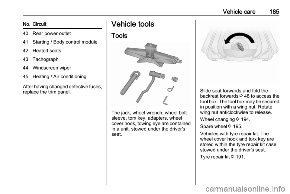
The jack, wheel wrench, wheel bolt
sleeve, torx key, adapters, wheel
cover hook, towing eye are contained
in a unit, stowed under the driver's
seat.
Slide seat forwards and fold the
backrest forwards 3 48 to access the
tool box. The tool box may be secured
in position with a wing nut. Rotate
wing nut anticlockwise to release.
Wheel changing 3 194.
Spare wheel 3 195.
Vehicles with tyre repair kit: The wheel cover hook and torx key are
stored within the tyre repair kit case,
stowed under the driver's seat.
Tyre repair kit 3 191.
Page 188 of 237

186Vehicle careWheels and tyres
Tyre condition, wheel condition Drive over edges slowly and at right
angles if possible. Driving over sharp
edges can cause tyre and wheel
damage. Do not trap tyres on the kerb when parking.
Regularly check the wheels for
damage. Seek the assistance of a
workshop in the event of damage or
unusual wear.
We recommend not swapping the
front wheels with the rear wheels and
vice versa, as this can affect vehicle
stability. Always use less worn tyres
on the rear axle.
Tyres
Factory-fitted tyres are matched to
the chassis and offer optimum driving comfort and safety.Winter tyres
Winter tyres improve driving safety at temperatures below 7 °C and should
therefore be fitted on all wheels.
In accordance with country-specific
regulations, a notice indicating the
maximum permissible speed for the
tyres must be affixed within the
driver's field of vision.
Tyre designations
E.g. 195/65 R 16 C 88 Q195:Tyre width, mm65:Cross-section ratio (tyre height
to tyre width), %R:Belt type: RadialRF:Type: RunFlat16:Wheel diameter, inchesC:Cargo or commercial use88:Load index e.g. 88 is
equivalent to 567 kgQ:Speed code letter
Speed code letter:
Q:up to 160 km/hS:up to 180 km/hT:up to 190 km/hH:up to 210 km/hV:up to 240 km/hW:up to 270 km/h
Choose a tyre appropriate for the
maximum speed of your vehicle.
The maximum speed is achievable at kerb weight with driver (75 kg) plus
125 kg payload. Optional equipment
could reduce the maximum speed of
the vehicle.
Directional tyres
Fit directional tyres such that they roll in the direction of travel. The rolling
direction is indicated by a symbol
(e.g. an arrow) on the sidewall.
Tyre pressure
Check the pressure of cold tyres at
least every 14 days and before any
long journey. Do not forget the spare
wheel. This also applies to vehicles
with tyre pressure monitoring system.
Page 189 of 237

Vehicle care187
The tyre pressure information label
on the driver's door frame indicates
the original equipment tyres and the
correspondent tyre pressures.
Always inflate tyres to the pressures
shown on the label.
Tyre pressures 3 220.
The tyre pressure data refers to cold tyres. It applies to summer and winter tyres.
Always inflate the spare tyre to the
pressure specified for full load.
Incorrect tyre pressures will impair
safety, vehicle handling, comfort and
fuel economy and will increase tyre
wear.
Tyre pressures differ depending on
various options. For the correct tyre
pressure value, follow the procedure
below:
1. Identify the engine identifier code.
Engine data 3 210.
2. Identify the respective tyre.
The tyre pressure tables show all
possible tyre combinations 3 220.
For the tyres approved for your
vehicle, refer to the EEC Certificate of Conformity provided with your vehicle
or other national registration
documents.
The driver is responsible for correct adjustment of tyre pressure.9 Warning
If the pressure is too low, this can
result in considerable tyre warm-
up and internal damage, leading to tread separation and even to tyre
blow-out at high speeds.
9 Warning
For specific tyres the
recommended tyre pressure as
shown in the tyre pressure table may exceed the maximum tyre
pressure as indicated on the tyre.
Never exceed the maximum tyre
pressure as indicated on the tyre.
Temperature dependency
Tyre pressure depends on the
temperature of the tyre. During
driving, tyre temperature and
pressure increase.
Tyre pressure values provided on the
tyre information label and tyre
pressure chart are valid for cold tyres, which means at 20 °C. The pressure
increases by nearly 10 kPa (0.1 bar)
for a 10 °C temperature increase.
This must be considered when warm
tyres are checked.
Page 190 of 237
188Vehicle careTrailer towing
When towing a trailer with a fully
laden vehicle, the tyre pressure must
be increased by 20 kPa/0.2 bar
(3.0 psi) and the maximum speed
limited to 100 km/h.
Trailer towing 3 162.
Tyre pressure monitoring
system
The tyre pressure monitoring system
uses radio and sensor technology to
check tyre pressure levels.Caution
Tyre pressure monitoring system
warns only about low tyre pressure condition and does not replace
regular tyre maintenance by the
driver.
All wheels must be equipped with pressure sensors and the tyres must
have the prescribed pressure.
Note
In countries where the tyre pressure
monitoring system is legally
required, the use of wheels without
pressure sensors will invalidate the
vehicle operating permit.
The tyre pressure monitoring system
sensors monitor the air pressure in
the tyres and transmit tyre pressure
readings to a receiver located in the
vehicle.
Tyre pressure chart 3 220.
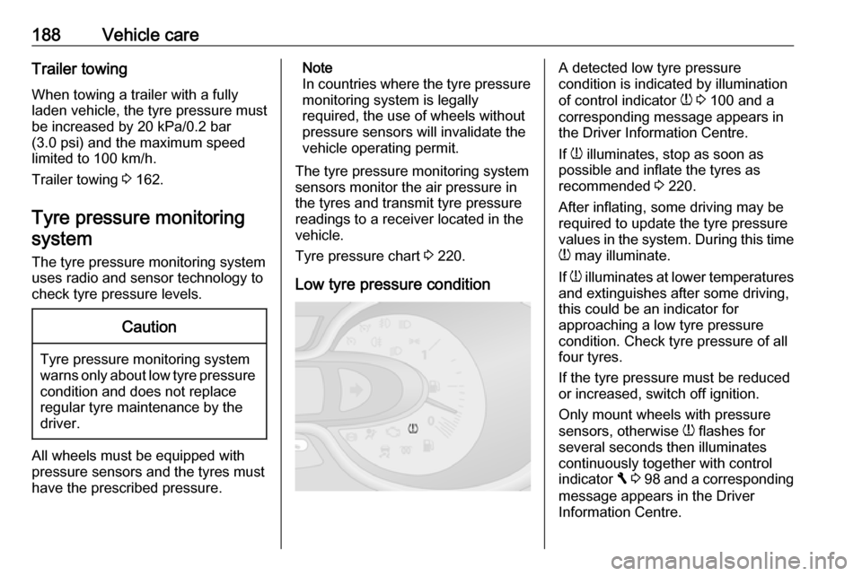
Low tyre pressure conditionA detected low tyre pressure
condition is indicated by illumination
of control indicator w 3 100 and a
corresponding message appears in
the Driver Information Centre.
If w illuminates, stop as soon as
possible and inflate the tyres as
recommended 3 220.
After inflating, some driving may be
required to update the tyre pressure
values in the system. During this time
w may illuminate.
If w illuminates at lower temperatures
and extinguishes after some driving,
this could be an indicator for
approaching a low tyre pressure
condition. Check tyre pressure of all
four tyres.
If the tyre pressure must be reduced
or increased, switch off ignition.
Only mount wheels with pressure
sensors, otherwise w flashes for
several seconds then illuminates
continuously together with control
indicator F 3 98 and a corresponding
message appears in the Driver
Information Centre.