ECU OPEL VIVARO B 2018 Manual user
[x] Cancel search | Manufacturer: OPEL, Model Year: 2018, Model line: VIVARO B, Model: OPEL VIVARO B 2018Pages: 237, PDF Size: 5.57 MB
Page 80 of 237
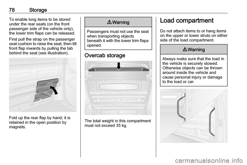
78StorageTo enable long items to be stored
under the rear seats (on the front
passenger side of the vehicle only),
the lower trim flaps can be released.
First pull the strap on the passenger
seat cushion to raise the seat, then tilt
front flap inwards by pulling the tab
behind the seat (see illustration).
Fold up the rear flap by hand; it is
retained in the open position by
magnets.
9 Warning
Passengers must not use the seat
when transporting objects
beneath it with the lower trim flaps
opened.
Overcab storage
The total weight in this compartment
must not exceed 35 kg.
Load compartment
Do not attach items to or hang items
on the upper or lower struts on either
side of the load compartment.9 Warning
Always make sure that the load in
the vehicle is securely stowed.
Otherwise objects can be thrown
around inside the vehicle and
cause personal injury or damage
to the load or car.
Page 81 of 237

Storage79Use the grab handles, located beside
the rear and sliding side door(s), to
assist during entry and exit of the load
compartment.
Load compartment cover
Rear parcel shelf Do not place any excessively heavy
or sharp-edged objects on the rear
parcel shelf.
The maximum load permissible is 50 kg.
The rear parcel shelf can be installed
in two positions, i.e. the upper
position or the lower position.
The rear parcel shelf may also be
folded up, allowing for greater
flexibility in the load compartment.
Removing
To remove, release parcel shelf from
its retainers on both sides.
If the rear seats 3 51 are in the folded
position, remove the parcel shelf and
store it horizontally in front of the folded rear seats.
Installing
Refit the parcel shelf by engaging in the retainers on both sides.
Lashing eyesLashing eyes are mounted in the load
compartment to enable cargo to be secured against slippage using
lashing straps or a luggage floor net.
Lashing eyes may be located on the
vehicle floor and / or in the sidewall.
The number and location of the
lashing eyes may vary depending on the vehicle.
Page 82 of 237

80Storage
Depending on vehicle, lashing eyes
may be located behind a trim panel in
the sidewall. To access lashing eye,
remove the trim panel by pulling it
upwards and place it in one of the rear storage pockets.The maximum force applied to the
lashing eyes should not exceed
500 daN / 5 kN / 5000 N.
Depending on country, the maximum
force may be shown on a label.
Note
Specifications on the label always
have priority over those given in this manual.
Loading information 3 82.
Safety net
The safety net can be installed behind the front seats or the rear seats.
Passengers must not be transported
behind the safety net.
Installing
Release the covers in the roof lining
(using a flat blade screwdriver) to
access the mountings, then insert the
load compartment net rods into the
left and right mounting locations and secure.
Page 84 of 237

82StorageWarning triangle
The warning triangle can be
accommodated in the space under
the seats.
Underseat storage 3 76.
First aid kit
The first aid kit can be accommodated
in the space under the seats.
Underseat storage 3 76.Roof rack system
Roof rackFor safety reasons and to avoid
damage to the roof, the vehicle
approved roof rack system is
recommended. For further
information, contact your workshop.
Follow the installation instructions
and remove the roof rack when not in
use.
Note
If tyres of size 215/60 R17 C are
fitted, consult a workshop before
installing a roof rack.
Refer to "Loading information" below
for further information.Loading information
● Heavy objects in the load compartment should be evenly
distributed and placed as far
forward as possible. If objects
can be stacked, the heavier
objects should be placed at the
bottom.
● Secure objects with lashing straps attached to lashing eyes
3 79.
● Secure loose objects in load compartment to prevent sliding.
● When transporting objects in the load compartment, the backrestsof the rear seats must not be
angled forward.
● Do not allow the load to protrude above the upper edge of the
backrests.
● Do not place any objects on the instrument panel.
● The load must not obstruct the operation of the pedals, parking
brake and gear selector, or
Page 85 of 237

Storage83hinder the freedom of movement
of the driver. Do not place any
unsecured objects in the interior.
● Do not drive with an open load compartment. In addition, the
number plate is only
distinguishable and illuminated correctly if the doors are closed.9 Warning
Always make sure that the load in
the vehicle is securely stowed.
Otherwise objects can be thrown
around inside the vehicle and
cause personal injury or damage
to the load or car.
● The payload is the difference between the permitted gross
vehicle weight (see identification
plate 3 208) and the EC kerb
weight.
To calculate the payload, enter
the data for your vehicle in the
Weights table at the front of this
manual.
The EC kerb weight includes
weights for the driver (68 kg),
luggage (7 kg) and all fluids (fuel
tank 90% full).
Optional equipment and
accessories increase the kerb
weight.
● Driving with a roof load increases
the sensitivity of the vehicle to
cross-winds and has a
detrimental effect on vehicle
handling due to the vehicle's
higher centre of gravity.
Distribute the load evenly and
secure it properly with retaining
straps. Adjust the tyre pressure
and vehicle speed according to
the load conditions. Check and
retighten the straps frequently.
Do not drive faster than
120 km/h.
The permissible roof load is
200 kg for H1 Roof height
variants and 150 kg for H2 Roof
height variants (excludes
Platform cab conversions). The
roof load is the combined weight
of the roof rack and the load.
Page 127 of 237

Climate control125Open the cover and replace the
battery (Type A: CR 2430, Type B:
2CR 11108, or equivalent), ensuring
the new battery is correctly installed
with the positive ( <) side facing the
positive terminals. Replace the cover securely.
Dispose of old batteries in
accordance with environmental
regulations.
Batteries do not belong in household
waste. They must be disposed of at
an appropriate recycling collection
point.
Operation (Type A)
Heating Y
Select Y in the menu bar and press
G to confirm. The predetermined
heating duration, e.g. L 30, flashes in
the display. The factory setting is 30 minutes.
Adjust the heating duration using k
or l and confirm. The value can be
set from ten to 120 minutes. Due to
the power consumption, note the
heating duration.
To switch off, select Y in the menu bar
again and press d.
Ventilation x
Select x in the menu bar and press
G to confirm.
Adjust the ventilation duration using k or l and confirm. The value can
be set from ten to 120 minutes. Due
to the power consumption, note the
heating duration.
To switch off, select x in the menu bar
again and press d.
Programming P
Up to three preset departure times
can be programmed, either during
one day or over one week.
● Select P in the menu bar and
press G to confirm.
● Select desired preset memory number P1, P2 or P3 and
confirm.● Select F and confirm.
● Select weekday or weekday group and confirm.
● Select hour and confirm.
● Select minutes and confirm.
● Select Y or x and confirm.
● Select ECO or HIGH and confirm.
● Select duration and confirm.
● Press d to exit.
Repeat the procedure to programme
the other preset memory numbers if
required.
To activate a desired preset memory
number select P1, P2 or P3, then
select On and confirm.
When a program is activated P and
Y will be displayed together.
To deactivate a preset memory,
select P1, P2 or P3, then select Off
and confirm.
Heating stops automatically
five minutes after the programmed
departure time.
Page 170 of 237
168Vehicle care
We recommend the use of the same
grade of engine oil that was used at
the last change.
The engine oil level must not exceed
the maximum mark MAX on the
dipstick.
Caution
Overfilled engine oil must be
drained or suctioned out.
To prevent spillage when
replenishing the engine oil, we
recommend using a funnel to top-up the engine oil. Ensure funnel is
securely located onto the filler pipe.
After topping-up, put the funnel into a
plastic bag and stow it securely.
A stabilization of the engine oil
consumption will not take place until the vehicle has been driven several
thousand kilometres. Only then can
the actual degree of consumption be
established.
If consumption exceeds more than
0.6 litres every 1000 km after this
running-in period, consult a
workshop.
Capacities 3 219.
Fit the cap on straight and tighten it.Engine air filter
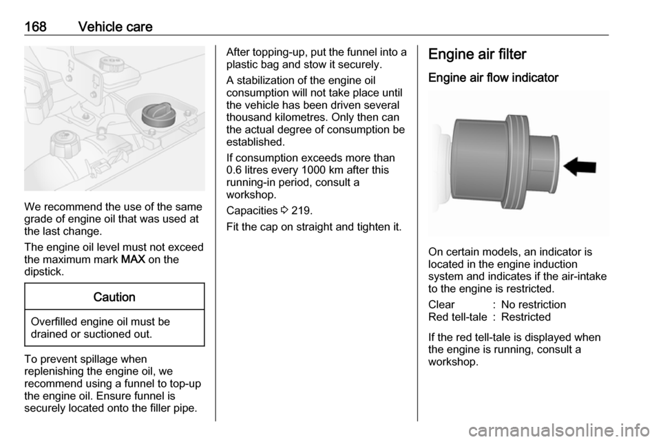
Engine air flow indicator
On certain models, an indicator is
located in the engine induction
system and indicates if the air-intake
to the engine is restricted.
Clear:No restrictionRed tell-tale:Restricted
If the red tell-tale is displayed when
the engine is running, consult a
workshop.
Page 176 of 237
174Vehicle careWith power button
● Insert the electronic key in thecard reader.
● Press START/STOP without
pressing any of the pedals.
● Wait a few minutes before starting engine.
Power button 3 132.
If the engine fails to start, seek the
assistance of a workshop.
Starting the engine 3 134.
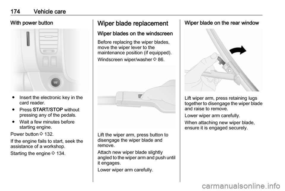
Wiper blade replacement
Wiper blades on the windscreen
Before replacing the wiper blades,
move the wiper lever to the
maintenance position (if equipped).
Windscreen wiper/washer 3 86.
Lift the wiper arm, press button to
disengage the wiper blade and
remove.
Attach new wiper blade slightly
angled to the wiper arm and push until
it engages.
Lower wiper arm carefully.
Wiper blade on the rear window
Lift wiper arm, press retaining lugs
together to disengage the wiper blade
and raise to remove.
Lower wiper arm carefully.
When attaching new wiper blade,
ensure it is engaged securely.
Page 179 of 237
Vehicle care1772.Carefully pull lamp assembly from
retaining pins on the outer side
and remove.
3. Detach wiring connector from lamp assembly.
4. Rotate bulb holder anticlockwiseto separate from lamp.
5. Renew bulb.
6. Push to install the bulb holder into
the lamp, then rotate clockwise to secure.
7. Reattach wiring connector to lamp
assembly and check that it is
located correctly.
8. Replace lamp assembly into original position, ensuring that it isseated correctly on retaining pins.
9. Replace the three bolts.
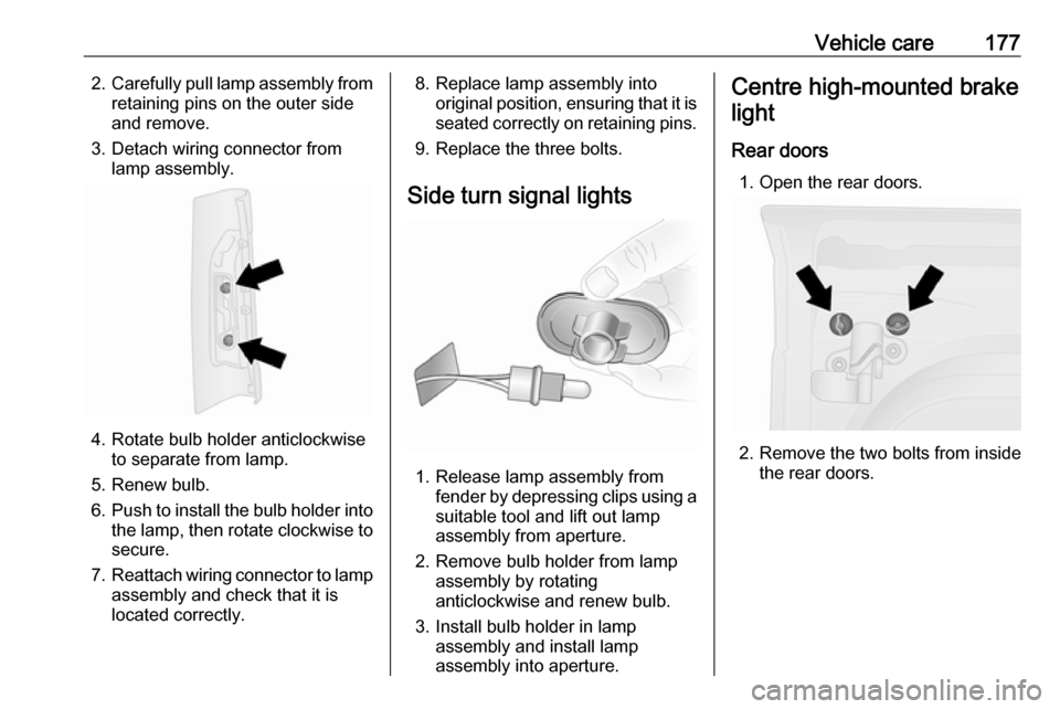
Side turn signal lights
1. Release lamp assembly from fender by depressing clips using a
suitable tool and lift out lamp
assembly from aperture.
2. Remove bulb holder from lamp assembly by rotating
anticlockwise and renew bulb.
3. Install bulb holder in lamp assembly and install lamp
assembly into aperture.
Centre high-mounted brake
light
Rear doors 1. Open the rear doors.
2. Remove the two bolts from inside the rear doors.
Page 181 of 237
Vehicle care1795.Push to install the bulb holder into
the lamp assembly, then rotate
clockwise to secure.
6. Reattach wiring connector to lamp
assembly.
7. Install lamp assembly with the two bolts.
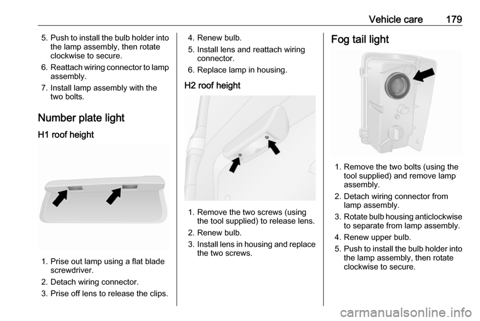
Number plate light
H1 roof height
1. Prise out lamp using a flat blade screwdriver.
2. Detach wiring connector.
3. Prise off lens to release the clips.
4. Renew bulb.
5. Install lens and reattach wiring connector.
6. Replace lamp in housing.
H2 roof height
1. Remove the two screws (using the tool supplied) to release lens.
2. Renew bulb.
3. Install lens in housing and replace
the two screws.
Fog tail light
1. Remove the two bolts (using the tool supplied) and remove lamp
assembly.
2. Detach wiring connector from lamp assembly.
3. Rotate bulb housing anticlockwise
to separate from lamp assembly.
4. Renew upper bulb.
5. Push to install the bulb holder into
the lamp assembly, then rotate
clockwise to secure.