ignition OPEL VIVARO B 2018 Manual user
[x] Cancel search | Manufacturer: OPEL, Model Year: 2018, Model line: VIVARO B, Model: OPEL VIVARO B 2018Pages: 237, PDF Size: 5.57 MB
Page 158 of 237

156Driving and operatingAn obstacle is indicated by buzzers
and, depending on vehicle, is also
indicated in the Info-Display. The
interval between the buzzers
becomes shorter as the vehicle gets
closer to the obstacle. When the
distance is less than 30 cm, the buzzer is continuous.
Note
In versions with Info-Display
indication, the volume of the buzzer
can be adjusted via the Infotainment
system. Refer to Infotainment
manual for further information.
DeactivationIt is possible to permanently or
temporarily deactivate the system.
Note
In versions with Info-Display
indication, the function can be
deactivated via the Infotainment
system. Refer to Infotainment
manual for further information.
Temporary deactivation
Temporarily deactivate the system by
pressing r on the instrument panel
with the ignition on. LED illuminates in
the button when deactivated.
When reverse gear is selected, no
acoustic signal will sound, indicating
deactivation.
The function is reactivated by
pressing r again or the next time
the ignition is switched on.
Permanent deactivation
Permanently deactivate the system
by pressing and holding r on the
instrument panel for approx.
three seconds with the ignition on.
LED illuminates continuously in the
button when permanently
deactivated.The system is deactivated and will not
operate. When reverse gear is
selected, no acoustic signal will
sound, indicating deactivation.
The function is reactivated by
pressing and holding r for approx.
three seconds.
Fault
If the system detects an operating fault, when selecting reverse gear a
continuous acoustic alarm will sound
for approx. five seconds, a
corresponding message appears in
the Driver Information Centre 3 102
and F illuminates in the instrument
cluster 3 98. Consult a workshop to
have the cause of the fault remedied.Caution
When reversing, the area should
be free from obstacles which could impact on the underside of the
vehicle.
Impact to the rear axle, which may
not be visible, could lead to
uncharacteristic changes in the
Page 162 of 237

160Driving and operatingThe flow and filterability of diesel fuelsare temperature-dependent. When
temperatures are low, refuel with
diesel fuel with guaranteed winter
properties.
Diesel fuel filter 3 173.
Diesel fuel system bleeding 3 173.
Low temperature operation At temperatures below 0 °C, somediesel products with biodiesel blends
may clog, freeze or gel, which may
affect the fuel supply system. Starting
and engine operation may not work
properly. Make sure to fill winter
grade diesel fuel at ambient
temperatures below 0 °C.
Arctic grade diesel fuel can be used
in extreme cold temperatures below
-20 °C. Using this fuel grade in warm
or hot climates is not recommended
and may cause engine stalling, poor starting or damage on the fuel
injection system.Refuelling9 Danger
Before refuelling, switch off engine
and any external heaters with
combustion chambers.
Vehicles with stop-start system:
The engine must be switched off
and the ignition key removed, to avoid risk of engine being
restarted automatically by the
system.
Switch off any mobile phones.
Follow the operating and safety
instructions of the filling station
when refuelling.
9 Danger
Fuel is flammable and explosive.
No smoking. No naked flames or
sparks.
If you can smell fuel in your
vehicle, have the cause of this
remedied immediately by a
workshop.
Caution
In case of misfuelling, do not
switch on ignition.
Note
To ensure the fuel level is displayed
correctly, the ignition must be
switched off before refuelling. Avoid
minor fuel top-ups (e.g. less than
five litres) to ensure accurate
readings.
The fuel filler flap is located on the left-
hand side of the vehicle.
The fuel filler flap can only be opened
if the vehicle is unlocked and the left- hand door is opened.
Note
Do not open the left-hand sliding
side door during refuelling.
Pull flap to open.
Page 163 of 237

Driving and operating161Caution
In vehicles with AdBlue, the
AdBlue protective cap is the blue
lower cap 3 141 , and the fuel filler
cap is the black upper cap
(arrowed in illustration).
In case of misfuelling, do not
switch on ignition. Seek the
assistance of a workshop
immediately.
To open the fuel filler cap, turn
anticlockwise.
The fuel filler cap can be retained in
the bracket on the fuel filler flap.
For refuelling, fully insert the pump
nozzle and switch it on.
After automatic cut-off, it can be
topped up by operating the pump
nozzle a maximum of two more times.Caution
Wipe off any overflowing fuel
immediately.
When refuelling is complete, replace
the fuel filler cap and turn clockwise
as far as it will go.
Close the fuel filler flap.
Fuel filler cap Only use genuine fuel filler caps.Diesel-engined vehicles have special
fuel filler caps.
Fuel consumption - CO 2-
Emissions
The values for fuel consumption
(combined) of the model Opel Vivaro
is within a range of 7.4 to
5.7 l/100 km.
Depending on country, the fuel
consumption is displayed in km/l. In
this case, the fuel consumption
(combined) of the model Opel Vivaro
is within a range of approx. 13.5 to
17.5 km/l.
The CO 2 emission (combined) is
within a range of 195 to 149 g/km.
For the values specific to your
vehicle, refer to the EEC Certificate of Conformity provided with your vehicle
or other national registration
documents.
General information
The official fuel consumption and
specific CO 2 emission figures quoted
relate to the EU base model with
standard equipment.
Fuel consumption data and CO 2
emission data are determined
according to regulation
R (EC) No. 715/2007 (in the latest
applicable version), taking into
consideration the vehicle weight in
running order, as specified by the
regulation.
Page 168 of 237

166Vehicle careEnd-of-life vehicle recoveryInformation on end-of-life vehicle
recovery centres and the recycling of
end-of-life vehicles is available on our website, where legally required. Only
entrust this work to an authorised
recycling centre.Vehicle checks
Performing work9 Warning
Only perform engine compartment
checks when the ignition is off.
The vehicle must not be in an
Autostop 3 136.
The cooling fan may start
operating even if the ignition is off.
9 Danger
The ignition system generates
extremely high voltages. Do not
touch.
The caps for topping up the engine oil, the coolant, the brake fluid, the
washer fluid and the oil dipstick
handle are yellow for ease of
identification.
Bonnet
Opening
Pull the release lever and return it to
its original position.
Page 173 of 237
Vehicle care171The brake fluid level must be between
the MINI and MAXI marks.
When topping up, ensure maximum
cleanliness as contamination of the
brake fluid can lead to brake system
malfunctions. Have the cause of the
loss of brake fluid remedied by a
workshop.
Only use high-performance brake
fluid approved for your vehicle.
Brake fluid 3 205.
Vehicle battery
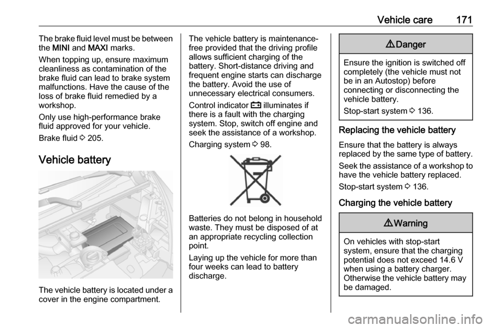
The vehicle battery is located under a cover in the engine compartment.
The vehicle battery is maintenance-
free provided that the driving profile
allows sufficient charging of the
battery. Short-distance driving and
frequent engine starts can discharge
the battery. Avoid the use of
unnecessary electrical consumers.
Control indicator p illuminates if
there is a fault with the charging
system. Stop, switch off engine and
seek the assistance of a workshop.
Charging system 3 98.
Batteries do not belong in household
waste. They must be disposed of at
an appropriate recycling collection
point.
Laying up the vehicle for more than
four weeks can lead to battery
discharge.
9 Danger
Ensure the ignition is switched off
completely (the vehicle must not
be in an Autostop) before
connecting or disconnecting the
vehicle battery.
Stop-start system 3 136.
Replacing the vehicle battery
Ensure that the battery is alwaysreplaced by the same type of battery.
Seek the assistance of a workshop to
have the vehicle battery replaced.
Stop-start system 3 136.
Charging the vehicle battery
9 Warning
On vehicles with stop-start
system, ensure that the charging potential does not exceed 14.6 V
when using a battery charger.
Otherwise the vehicle battery may be damaged.
Page 175 of 237
Vehicle care173disconnecting the main vehicle
battery or before jump starting the vehicle.
The terminals are designed for
additional electrical consumers up to
a maximum of 50 A.
Jump starting 3 197.
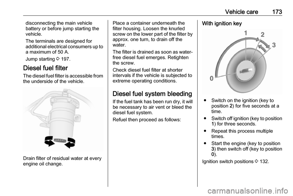
Diesel fuel filter The diesel fuel filter is accessible from the underside of the vehicle.
Drain filter of residual water at every
engine oil change.
Place a container underneath the
filter housing. Loosen the knurled
screw on the lower part of the filter by approx. one turn, to drain off the
water.
The filter is drained as soon as water-
free diesel fuel emerges. Retighten
the screw.
Check diesel fuel filter at shorter
intervals if the vehicle is subjected to
extreme operating conditions.
Diesel fuel system bleeding
If the fuel tank has been run dry, it will be necessary to air vent or bleed the
diesel fuel system.
Refuel then proceed as follows:With ignition key
● Switch on the ignition (key to position 2) for five seconds at a
time.
● Switch off ignition (key to position
1 ) for three seconds.
● Repeat this process multiple times.
● Start the engine (key to position 3) then switch off (key to position
0 ).
Ignition switch positions 3 132.
Page 177 of 237
Vehicle care175Bulb replacement
Switch off the ignition and turn off the
relevant switch or close the doors.
Only hold a new bulb at the base. Do not touch the bulb glass with bare
hands.
Use only the same bulb type for
replacement.
Bulb check
After a bulb replacement, switch on
the ignition, operate and check the
lights.
Headlights Low beam and high beam
Replace headlight bulbs from within
the engine compartment.
1. Remove protective cover by rotating it anticlockwise.
2. Detach wiring connector.
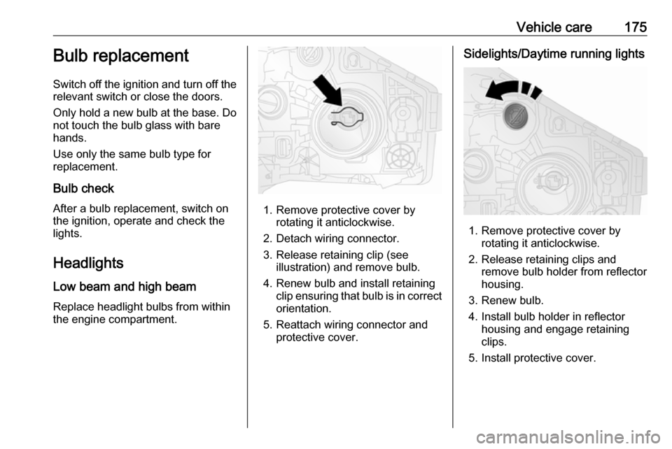
3. Release retaining clip (see illustration) and remove bulb.
4. Renew bulb and install retaining clip ensuring that bulb is in correct
orientation.
5. Reattach wiring connector and protective cover.
Sidelights/Daytime running lights
1. Remove protective cover byrotating it anticlockwise.
2. Release retaining clips and remove bulb holder from reflector
housing.
3. Renew bulb.
4. Install bulb holder in reflector housing and engage retaining
clips.
5. Install protective cover.
Page 183 of 237
Vehicle care181Electrical system
Fuses Data on the replacement fuse must
match the data on the defective fuse.
There are two fuse boxes in the
vehicle:
● on the left-hand side of the instrument panel, behind the trim
panel
● in the engine compartment located next to the battery
Note
The engine compartment fuse box
should only be accessed by a
workshop.
Before replacing a fuse, turn off the
respective switch and the ignition.
There are different types of fuses in
the vehicle.
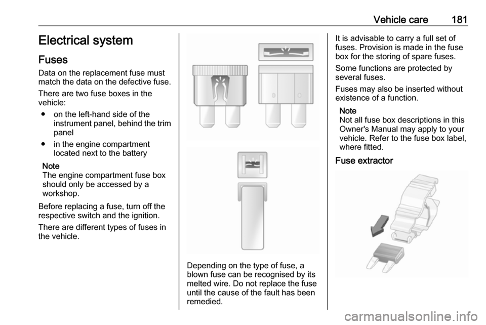
Depending on the type of fuse, a
blown fuse can be recognised by its
melted wire. Do not replace the fuse until the cause of the fault has been
remedied.
It is advisable to carry a full set of
fuses. Provision is made in the fuse
box for the storing of spare fuses.
Some functions are protected by
several fuses.
Fuses may also be inserted without existence of a function.
Note
Not all fuse box descriptions in this
Owner's Manual may apply to your
vehicle. Refer to the fuse box label,
where fitted.
Fuse extractor
Page 190 of 237
188Vehicle careTrailer towing
When towing a trailer with a fully
laden vehicle, the tyre pressure must
be increased by 20 kPa/0.2 bar
(3.0 psi) and the maximum speed
limited to 100 km/h.
Trailer towing 3 162.
Tyre pressure monitoring
system
The tyre pressure monitoring system
uses radio and sensor technology to
check tyre pressure levels.Caution
Tyre pressure monitoring system
warns only about low tyre pressure condition and does not replace
regular tyre maintenance by the
driver.
All wheels must be equipped with pressure sensors and the tyres must
have the prescribed pressure.
Note
In countries where the tyre pressure
monitoring system is legally
required, the use of wheels without
pressure sensors will invalidate the
vehicle operating permit.
The tyre pressure monitoring system
sensors monitor the air pressure in
the tyres and transmit tyre pressure
readings to a receiver located in the
vehicle.
Tyre pressure chart 3 220.
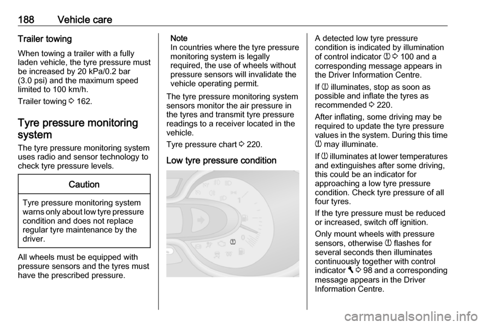
Low tyre pressure conditionA detected low tyre pressure
condition is indicated by illumination
of control indicator w 3 100 and a
corresponding message appears in
the Driver Information Centre.
If w illuminates, stop as soon as
possible and inflate the tyres as
recommended 3 220.
After inflating, some driving may be
required to update the tyre pressure
values in the system. During this time
w may illuminate.
If w illuminates at lower temperatures
and extinguishes after some driving,
this could be an indicator for
approaching a low tyre pressure
condition. Check tyre pressure of all
four tyres.
If the tyre pressure must be reduced
or increased, switch off ignition.
Only mount wheels with pressure
sensors, otherwise w flashes for
several seconds then illuminates
continuously together with control
indicator F 3 98 and a corresponding
message appears in the Driver
Information Centre.
Page 191 of 237
Vehicle care189A spare wheel or temporary spare
wheel is not equipped with pressure
sensors. The tyre pressure
monitoring system is not operational
for these wheels. For the further three
wheels, the tyre pressure monitoring
system remains operational.
Control indicator w and the
corresponding message appears at
each ignition cycle until the tyres are
inflated to the correct tyre pressure.
Driver Information Centre 3 102.
Vehicle messages 3 103.
Puncture
A puncture or severely under-inflated
tyre is indicated by illumination of
control indicator w together with C
3 98 and a corresponding message
appears in the Driver Information
Centre. Stop vehicle and switch off
engine.
Tyre pressure 3 220.
Tyre repair kit 3 191.
Spare wheel 3 195.
Wheel changing 3 194.Relearn function
After a puncture has been repaired
and the driver has inflated the tyres to
the correct tyre pressure, the tyre
pressure monitoring system needs to recalculate.
Tyre pressure 3 220.
Tyre repair kit 3 191.
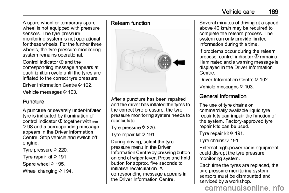
During driving, select the tyre
pressure menu in the Driver
Information Centre by pressing button
on end of wiper lever. Press and hold button for approx. five seconds to
initialise recalculation. A
corresponding message appears in
the Driver Information Centre.
Several minutes of driving at a speed above 40 km/h may be required to
complete the relearn process. The system can only provide limited
information during this time.
If problems occur during the relearn
process, control indicator w remains
illuminated and a warning message is displayed in the Driver Information
Centre.
Driver Information Centre 3 102.
Vehicle messages 3 103.
General information The use of tyre chains or
commercially available liquid tyre
repair kits can impair the function of
the system. Factory-approved tyre
repair kits can be used.
Tyre repair kit 3 191.
Tyre chains 3 191.
External high-power radio equipment
could disrupt the tyre pressure
monitoring system.
Each time the tyres are replaced, the
tyre pressure monitoring system
sensors must be dismounted and
serviced by a workshop.