light OPEL VIVARO C 2020.25 Manual user
[x] Cancel search | Manufacturer: OPEL, Model Year: 2020.25, Model line: VIVARO C, Model: OPEL VIVARO C 2020.25Pages: 287, PDF Size: 28.79 MB
Page 205 of 287

Driving and operating203● dazzle caused by headlamps ofoncoming vehicles, low sun,
reflections on damp roads,
leaving a tunnel, alternating
shade and light etc.
● windscreen area in front of the camera covered by dirt, snow,
stickers etc.
● no lane markings detected or multiple lane markings due to
roadworks
● close vehicles ahead
● winding roads or narrow roadsFuel
Fuel for diesel engines The Diesel engines are compatible
with bio-fuels that conform to current and future European standards and
and can be obtained from filling
stations:
Diesel fuel that meets standard
EN590 mixed with a biofuel that
meets standard EN14214 (possibly
containing up to 7% Fatty Acid Methyl
Ester)
Diesel fuel that meets standard
EN16734 mixed with a biofuel that
meets standard EN14214 (possibly
containing up to 10% Fatty Acid
Methyl Ester)
Paraffinic Diesel fuel that meets
standard EN15940 mixed with a
biofuel that meets standard
EN14214 (possibly containing up to
7% Fatty Acid Methyl Ester).
The use of B20 or B30 fuel meeting standard EN16709 is possible.
However, this use, even occasional, requires strict application of the
special servicing conditions referred
to as "Arduous conditions".
Page 207 of 287

Driving and operating205version, release the fuel filler flap by
pushing the flap or pulling at the right bottom corner.
Depending on the version, place the
key in the lock and unlock the cap.
To open, turn the cap slowly
anticlockwise.
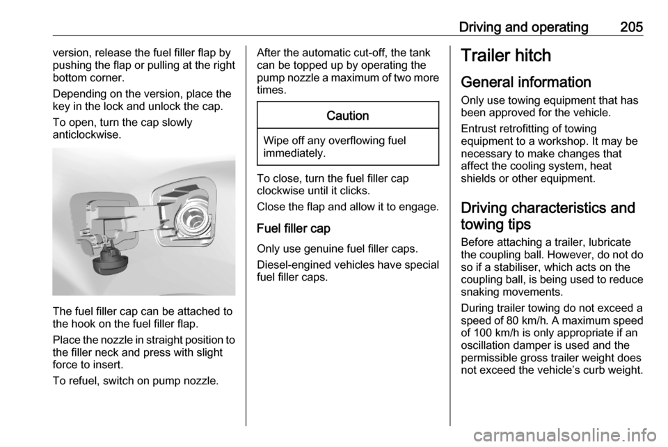
The fuel filler cap can be attached to
the hook on the fuel filler flap.
Place the nozzle in straight position to the filler neck and press with slight
force to insert.
To refuel, switch on pump nozzle.
After the automatic cut-off, the tank can be topped up by operating the
pump nozzle a maximum of two more
times.Caution
Wipe off any overflowing fuel
immediately.
To close, turn the fuel filler cap
clockwise until it clicks.
Close the flap and allow it to engage.
Fuel filler cap
Only use genuine fuel filler caps.
Diesel-engined vehicles have special fuel filler caps.
Trailer hitch
General information
Only use towing equipment that has
been approved for the vehicle.
Entrust retrofitting of towing
equipment to a workshop. It may be
necessary to make changes that
affect the cooling system, heat
shields or other equipment.
Driving characteristics and towing tips
Before attaching a trailer, lubricate
the coupling ball. However, do not do so if a stabiliser, which acts on thecoupling ball, is being used to reduce
snaking movements.
During trailer towing do not exceed a
speed of 80 km/h. A maximum speed
of 100 km/h is only appropriate if an
oscillation damper is used and the
permissible gross trailer weight does
not exceed the vehicle’s curb weight.
Page 208 of 287

206Driving and operatingFor trailers with low driving stability
and caravan trailers, the use of an
oscillation damper is strongly
recommended.
If the trailer starts snaking, drive more slowly, do not attempt to correct the
steering and brake sharply if
necessary.
When driving downhill, drive in the
same gear as if driving uphill and
drive at a similar speed.
If the outside temperature exceeds
37 °C, reduce the load on the trailer
to protect the engine of the vehicle.
At high outside temperatures it is
recommended to leave the engine
running for one or two minutes after
having stopped the vehicle in order to
faciliate cooling.
Adjust tyre pressure to the value
specified for full load 3 271.
Towing a trailer increases the braking
distance of the vehicle. To limit the
heating of the brakes, it is
recommended to use the braking
effect of the engine.By driving uphill, the temperature of
the coolant is increased. To reduce
heating, drive at a reduced speed and
pay attention to the coolant
temperature. If the control indicator
2 of the engine coolant temperature
gauge illuminates, stop the vehicle
and switch off engine as soon as
possible.
Trailer towing Trailer loadsThe permissible trailer loads are
vehicle and engine-dependent
maximum values which must not be
exceeded. The actual trailer load is
the difference between the actual
gross weight of the trailer and the
actual coupling socket load with the
trailer coupled.
The permissible trailer loads are
specified in the vehicle documents. In general, they are valid for gradients
up to 12%.
The permissible trailer load applies
up to the specified incline and at sea
level. Since engine power decreases
as altitude increases due to the airbecoming thinner, therefore reducing
climbing ability, the permissible gross
train weight also decreases by 10%
for every 1000 metres of altitude. The gross train weight does not have to be
reduced when driving on roads with
slight inclines (less than 8%, e.g.
motorways).
The permissible gross train weight
must not be exceeded. This weight is
specified on the identification plate
3 264.
When distributing the loads in the trailer, heavy objects should be
placed as close as possible to the
axle.
Vertical coupling load
The vertical coupling load is the load
exerted by the trailer on the coupling
ball. It can be varied by changing the
weight distribution when loading the
trailer.
The maximum permissible vertical
coupling load is specified on the
towing equipment identification plate
and in the vehicle documents.
Page 213 of 287

Vehicle care211Vehicle careGeneral Information...................212
Accessories and vehicle modifications .......................... 212
Vehicle storage ........................212
End-of-life vehicle recovery .....213
Vehicle checks ........................... 213
Performing work ......................213
Bonnet ..................................... 214
Engine oil ................................. 214
Engine coolant ......................... 215
Washer fluid ............................ 216
Brakes ..................................... 216
Brake fluid ............................... 216
Vehicle battery ......................... 217
Diesel fuel system bleeding .....219
Wiper blade replacement ........219
Bulb replacement .......................220
Halogen headlights ..................220
Xenon headlights .....................223
Front fog lights ......................... 224
Front turn lights .......................225
Tail lights ................................. 226
Side turn lights ......................... 228
Centre high-mounted brake light ......................................... 229Number plate light...................230
Interior lights ............................ 230
Electrical system ........................231
Fuses ....................................... 231
Engine compartment fuse box . 232
Instrument panel fuse box .......232
Vehicle tools .............................. 234
Tools ........................................ 234
Wheels and tyres .......................237
Winter tyres ............................. 237
Tyre designations ....................237
Tyre pressure .......................... 237
Tyre deflation detection
system .................................... 238
Tread depth ............................. 239
Changing tyre and wheel size . 240
Wheel covers ........................... 240
Tyre chains .............................. 240
Tyre repair kit .......................... 241
Wheel changing .......................244
Spare wheel ............................ 245
Jump starting ............................. 250
Towing ....................................... 251
Towing the vehicle ...................251
Towing another vehicle ...........252
Appearance care .......................253
Exterior care ............................ 253Interior care............................. 255
Floor mats ............................... 256
Page 220 of 287

218Vehicle careDischarge protection
Battery voltage
When the vehicle battery voltage is
running low, a warning message will
appear in the Driver Information
Centre.
When the vehicle is being driven, the
load reduction function temporarily
deactivates certain functions, such as
the air conditioning, the heated rear
window, heated steering wheel, etc.
The deactivated functions are
reactivated automatically as soon as
conditions permit.
Idle boost
If charging of the vehicle battery is
required due to battery condition, the
power output of the generator must be increased. This will be achieved by
an idle boost which may be audible.
A message appears in the Driver
Information Centre.
Power outlet
The power outlets are deactivated in
the event of low vehicle battery
voltage.Warning label
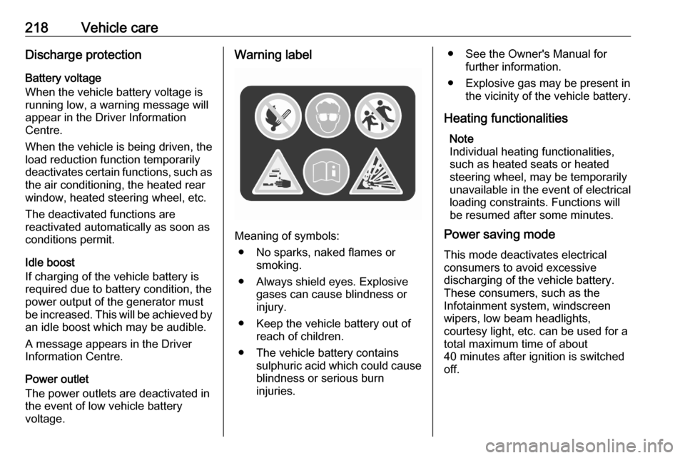
Meaning of symbols:
● No sparks, naked flames or smoking.
● Always shield eyes. Explosive gases can cause blindness or
injury.
● Keep the vehicle battery out of reach of children.
● The vehicle battery contains sulphuric acid which could cause
blindness or serious burn
injuries.
● See the Owner's Manual for further information.
● Explosive gas may be present in the vicinity of the vehicle battery.
Heating functionalities Note
Individual heating functionalities,
such as heated seats or heated
steering wheel, may be temporarily
unavailable in the event of electrical
loading constraints. Functions will
be resumed after some minutes.
Power saving mode
This mode deactivates electrical
consumers to avoid excessive
discharging of the vehicle battery.
These consumers, such as the
Infotainment system, windscreen
wipers, low beam headlights,
courtesy light, etc. can be used for a
total maximum time of about
40 minutes after ignition is switched
off.
Page 222 of 287

220Vehicle careLower the wiper arm carefully.Rear window
Lift the wiper arm. Disengage the
wiper blade as shown in the
illustration and remove.
Attach the wiper blade slightly angled
to the wiper arm and push until it
engages.
Lower the wiper arm carefully.
Bulb replacement
Switch off the ignition and switch off
the relevant switch or close the doors.
Only hold a new bulb at the base. Do not touch the bulb glass with bare
hands.
Use only the same bulb type for
replacement.
Replace headlight bulbs from within
the engine compartment.
Bulb check
After a bulb replacement switch on
the ignition, operate and check the
lights.
Halogen headlights Front turn lights 3 225.
Illustrations show the right headlight
unit.
Low beam bulb sits in outer chamber
( 2 )
High beam bulb sits in inner chamber
( 1 )
Parking light bulb sits in inner
chamber ( 1)
Daytime running light bulb sits in outer chamber ( 2)
Page 224 of 287

222Vehicle careWithdraw the bulb holder from the
reflector housing.
3. Detach the bulb from the bulb socket and replace the bulb.
4. Insert the bulb socket into the reflector housing.
5. Fit the cover.
Parking light
1. Remove the protective cover.
2. Press the clips on the bulb socket
to disengage and withdraw socket
from the reflector.
3. Remove the bulb from the socket by pulling.
4. Replace and insert the new bulb into the socket.
5. Insert the bulb socket into the housing.
Page 225 of 287

Vehicle care223Daytime running light
1. Remove the protective cover.
2.Press the clips on the bulb socket
to disengage and withdraw socket
from the reflector.
3. Remove the bulb from the socket by pulling.
4. Replace and insert the new bulb into the socket.
5. Insert the bulb socket into the housing.
Daytime running light with LEDs The daytime running light unit in the
lower bumper area is designed with
LEDs. In case of defective LEDs,
have them replaced by a workshop.
Xenon headlights
Front turn lights 3 225.
Illustrations show the right headlight
unit.
Low beam bulb sits in outer chamber
( 2 )
High beam bulb sits in inner chamber
( 1 )
Page 226 of 287

224Vehicle careLow beam9Danger
Xenon headlights work under
extremely high electrical voltage.
Do not touch. Have bulbs replaced by a workshop.
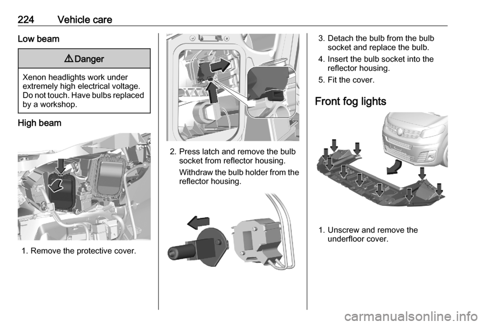
High beam
1. Remove the protective cover.
2. Press latch and remove the bulb socket from reflector housing.
Withdraw the bulb holder from the
reflector housing.
3. Detach the bulb from the bulb socket and replace the bulb.
4. Insert the bulb socket into the reflector housing.
5. Fit the cover.
Front fog lights
1. Unscrew and remove the underfloor cover.
Page 227 of 287

Vehicle care225
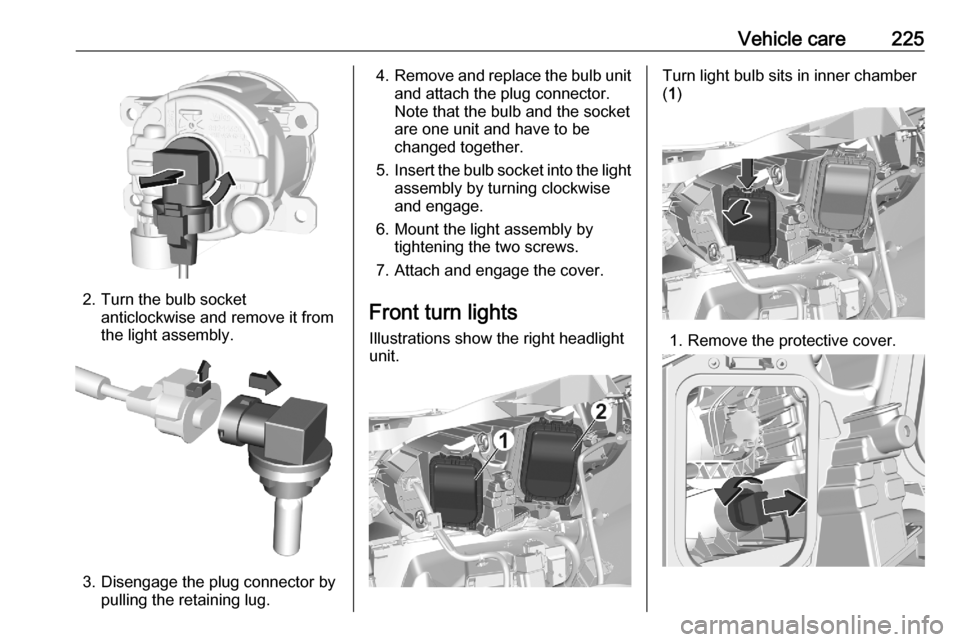
2. Turn the bulb socketanticlockwise and remove it from
the light assembly.
3. Disengage the plug connector by pulling the retaining lug.
4.Remove and replace the bulb unit
and attach the plug connector.
Note that the bulb and the socket
are one unit and have to be
changed together.
5. Insert the bulb socket into the light
assembly by turning clockwise
and engage.
6. Mount the light assembly by tightening the two screws.
7. Attach and engage the cover.
Front turn lights Illustrations show the right headlight
unit.Turn light bulb sits in inner chamber
( 1 )
1. Remove the protective cover.