light OPEL VIVARO C 2020.25 Manual user
[x] Cancel search | Manufacturer: OPEL, Model Year: 2020.25, Model line: VIVARO C, Model: OPEL VIVARO C 2020.25Pages: 287, PDF Size: 28.79 MB
Page 228 of 287

226Vehicle care2. Rotate the bulb socketanticlockwise to disengage and
withdraw from the reflector.
3. Slightly press down the bulb, turn it anticlockwise and remove it
from the socket.
4. Replace and insert the new bulb into socket by turning clockwise.
5. Insert the bulb socket into the reflector and turn clockwise.
Tail lights
Tail light assembly All body styles except platform cab
1. Vehicles with a cover hiding the lower tail light assembly screw:
remove cover by carefully
releasing its retaining lugs with a
screwdriver and tilting the cover
slightly towards the outside.
2. Unscrew and remove the two screws.
3. Vehicles with air vent or coverbehind the tail light, in the trim:
Remove air vent or cover.
Page 229 of 287

Vehicle care227
4. While holding the light assembly,push the retaining lug which holds
the tail light assembly in the body.
5. Carefully withdraw the tail light assembly from recess and
remove. Take care that the cable
duct remains in position.
6. Detach the cable from the retainer
in the light assembly.
7. Disengage the central retaining lug, pull the bulb carrier and
disengage the remaining retaining lugs.
8. Push the bulb slightly down, turn it and remove it from the bulb
carrier. Replace the bulb:
Tail light / parking light ( 1)
Reverse light ( 2)
Brake light / parking light ( 3)
Turn light / hazard warning flasher
( 4 )
9. Attach the bulb carrier to the light assembly.
10. Attach the cable to the retainer.
11. Attach the light assembly to the vehicle body and tighten both
screws.
Page 230 of 287
228Vehicle care12. Clip in cover which may havecovered the lower tail light
assembly screw.
13. Attach cover or air vent behind the
tail light if removed before.
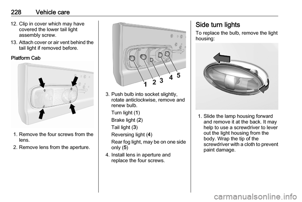
Platform Cab
1. Remove the four screws from the lens.
2. Remove lens from the aperture.
3. Push bulb into socket slightly, rotate anticlockwise, remove and
renew bulb.
Turn light ( 1)
Brake light ( 2)
Tail light ( 3)
Reversing light ( 4)
Rear fog light, may be on one side
only ( 5)
4. Install lens in aperture and replace the four screws.
Side turn lights
To replace the bulb, remove the light
housing:
1. Slide the lamp housing forward and remove it at the back. It may
help to use a screwdriver to lever
out the light housing from the
body. Wrap the tip of the
screwdriver with a cloth to prevent
paint damage.
Page 231 of 287

Vehicle care229
2.Pull the retaining lug upwards and
remove the bulb socket from the
plug connector.
3. Replace the complete unit.
4. Insert left end of the lamp, slide to
the left and insert right end.
Centre high-mounted brake light
Vehicles with hinged doors or
tailgate
1. Open the rear doors.
2. a) vehicles with tailgate:
Loose the inner trim from clips by
swiveling it upwards and
downwards. Pull trim off carefully.
b) vehicles with hinged doors:
Wrap a cloth around the tip of a
slot screwdriver to prevent paint
damage. Remove the inner cover
or air vent with the screwdriver.
3. Push the brake light assembly carefully out through the recess.
4. Detach the cable from the retainer
in the light assembly.
5. Remove the socket of the defect bulb by turning it a quarter turn
anti-clockwise.
6. Renew bulb.
7. Install brake light assembly like explained above, in reversed
order.
Page 232 of 287
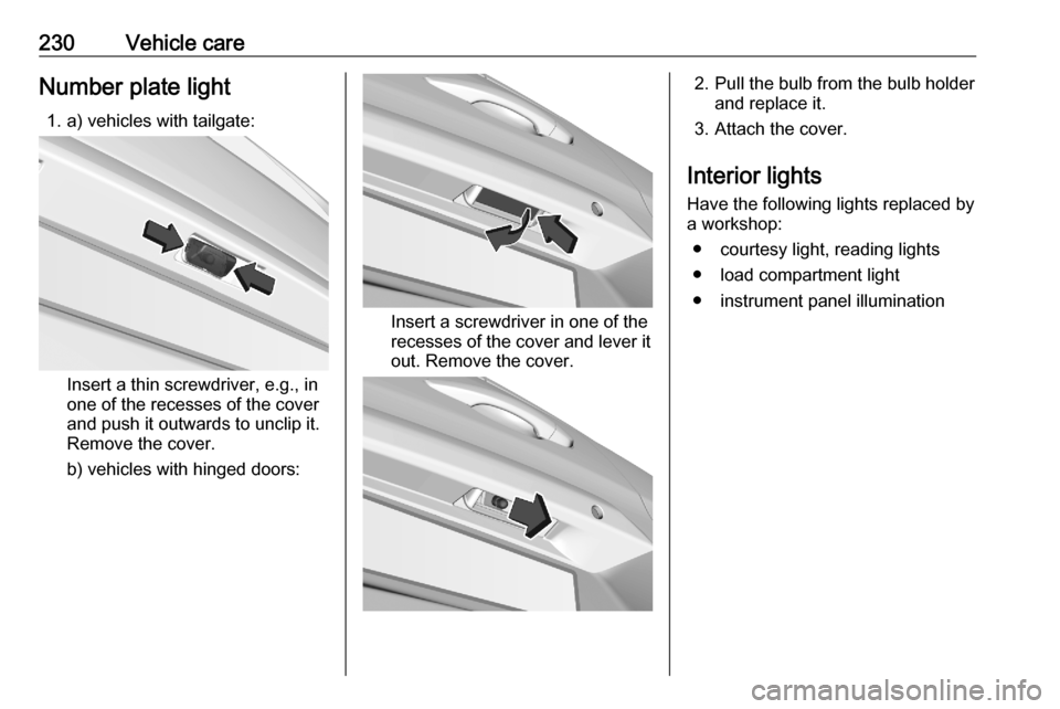
230Vehicle careNumber plate light1. a) vehicles with tailgate:
Insert a thin screwdriver, e.g., in
one of the recesses of the cover and push it outwards to unclip it.
Remove the cover.
b) vehicles with hinged doors:
Insert a screwdriver in one of the
recesses of the cover and lever it
out. Remove the cover.
2. Pull the bulb from the bulb holder and replace it.
3. Attach the cover.
Interior lights
Have the following lights replaced by
a workshop:
● courtesy light, reading lights
● load compartment light
● instrument panel illumination
Page 234 of 287
232Vehicle careEngine compartment fuse
box
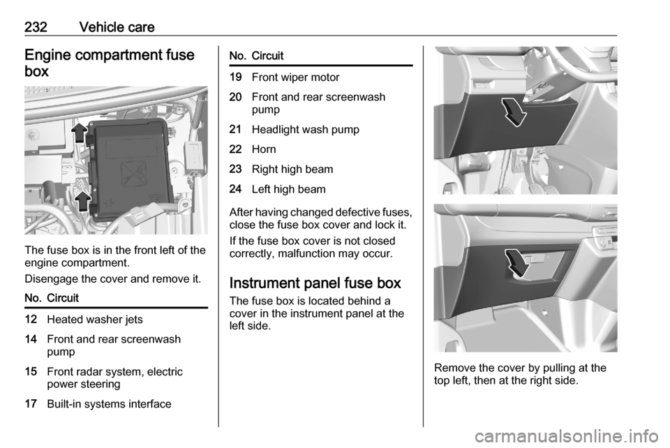
The fuse box is in the front left of the
engine compartment.
Disengage the cover and remove it.
No.Circuit12Heated washer jets14Front and rear screenwash
pump15Front radar system, electric
power steering17Built-in systems interfaceNo.Circuit19Front wiper motor20Front and rear screenwash
pump21Headlight wash pump22Horn23Right high beam24Left high beam
After having changed defective fuses,
close the fuse box cover and lock it.
If the fuse box cover is not closed
correctly, malfunction may occur.
Instrument panel fuse boxThe fuse box is located behind a
cover in the instrument panel at the
left side.
Remove the cover by pulling at the
top left, then at the right side.
Page 235 of 287
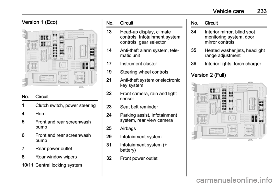
Vehicle care233Version 1 (Eco)No.Circuit1Clutch switch, power steering4Horn5Front and rear screenwash
pump6Front and rear screenwash
pump7Rear power outlet8Rear window wipers10/11Central locking systemNo.Circuit13Head-up display, climate
controls, Infotainment system
controls, gear selector14Anti-theft alarm system, tele‐
matic unit17Instrument cluster19Steering wheel controls21Anti-theft system or electronic key system22Front camera, rain and light
sensor23Seat belt reminder24Parking assist, Infotainment
system, rear view camera25Airbags29Infotainment system31Infotainment system (+
battery)32Front power outletNo.Circuit34Interior mirror, blind spot
monitoring system, door
mirror controls35Heated washer jets, headlight
range adjustment36Interior lights, torch charger
Version 2 (Full)
Page 236 of 287

234Vehicle careNo.Circuit1Anti-theft system or
electronic key system5Parking assist, Infotain‐
ment system, rear view
camera7Rear climate controls,
audio system amplifier8Rear window wipers10/11Central locking system12Anti-theft alarm system17Rear power outlet18Telematic unit21Interior lights, torch
charger22Interior lights, glovebox
light23Blind spot monitoring
system, door mirror
controls24Steering wheel controlsNo.Circuit25Headlight range adjust‐
ment26Seat belt reminder27Front camera, rain and
light sensor28Head-up display, front
climate controls, Info‐
tainment system
controls, gear selector30A or 30BAudio system (+
battery)31Airbag33Front power outlet35Instrument cluster36Infotainment systemVehicle tools
Tools
The tools are located in the box
underneath the left front seat.
Page 237 of 287
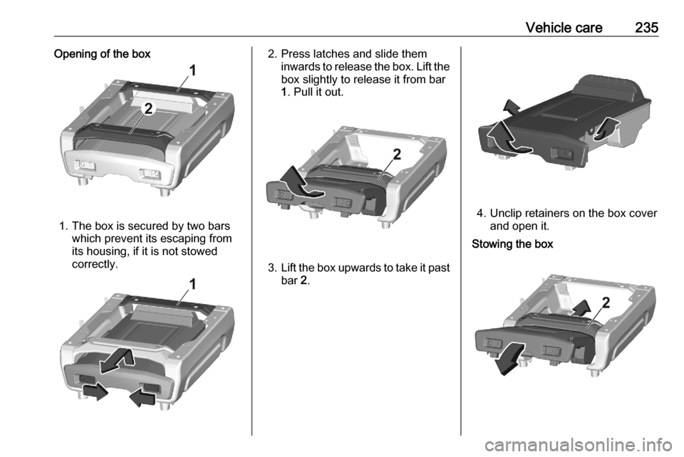
Vehicle care235Opening of the box
1. The box is secured by two barswhich prevent its escaping from
its housing, if it is not stowed
correctly.
2. Press latches and slide them inwards to release the box. Lift thebox slightly to release it from bar
1 . Pull it out.
3. Lift the box upwards to take it past
bar 2.
4. Unclip retainers on the box cover
and open it.
Stowing the box
Page 246 of 287

244Vehicle care
2. Disconnect the connector fromthe cartridge by turning it a quarter
turn anti-clockwise.
3. Pull pipe assembly out slightly, then disconnect connector from
the air hose by turning it a quarter
turn anticlockwise.
4. Remove air hose.
Keep the kit vertical and unscrew
the cartridge from the bottom.
5. To fit the new cartridge and new pipe, carry out these operations in
reverse order.
Wheel changing
Make the following preparations and
observe the following information:
● Park the vehicle on a level, firm and non-skid surface. The front
wheels must be in the straight-
ahead position.
● If necessary, place a chock under
the wheel diagonally opposite the
wheel to be changed.
● Apply the parking brake and engage first gear, reverse gear or
P .
● If the ground on which the vehicle
is standing is soft, a solid board
(max. 1 cm thick) should be
placed under the jack.
● Take heavy objects out of the vehicle before jacking up.
● No people or animals may be in the vehicle when it is jacked-up.
● Never crawl under a jacked-up vehicle.
● Do not start the vehicle when it is
raised on the jack.
● Before screwing in the wheel bolts, clean them.