clock OPEL ZAFIRA TOURER 2015 Owners Manual
[x] Cancel search | Manufacturer: OPEL, Model Year: 2015, Model line: ZAFIRA TOURER, Model: OPEL ZAFIRA TOURER 2015Pages: 299, PDF Size: 9.13 MB
Page 73 of 299
Storage71
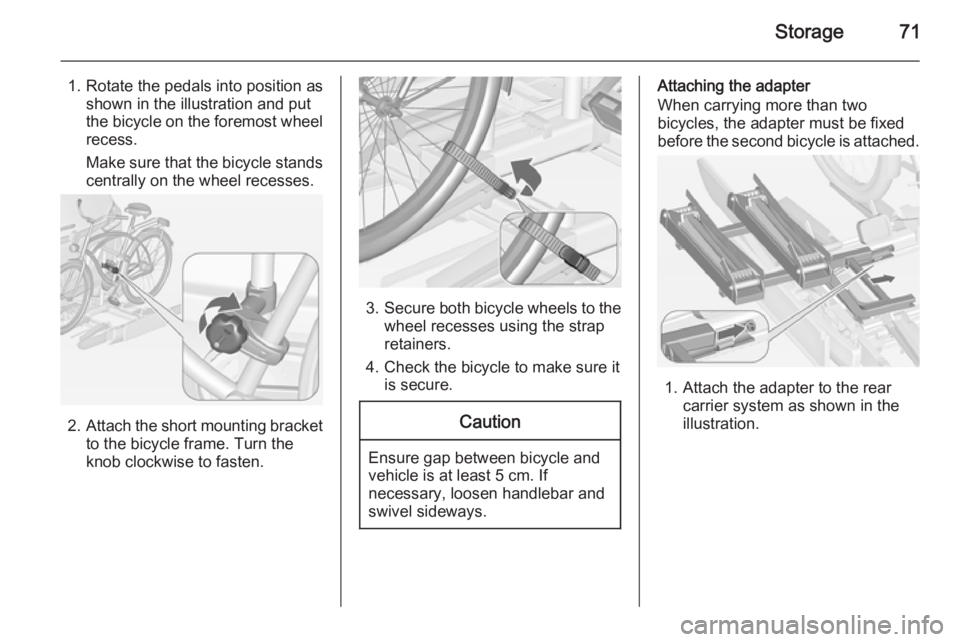
1. Rotate the pedals into position asshown in the illustration and put
the bicycle on the foremost wheel
recess.
Make sure that the bicycle stands centrally on the wheel recesses.
2. Attach the short mounting bracket
to the bicycle frame. Turn the
knob clockwise to fasten.
3. Secure both bicycle wheels to the
wheel recesses using the strap
retainers.
4. Check the bicycle to make sure it is secure.
Caution
Ensure gap between bicycle and
vehicle is at least 5 cm. If
necessary, loosen handlebar and swivel sideways.
Attaching the adapter
When carrying more than two
bicycles, the adapter must be fixed
before the second bicycle is attached.
1. Attach the adapter to the rear
carrier system as shown in the
illustration.
Page 76 of 299
74Storage
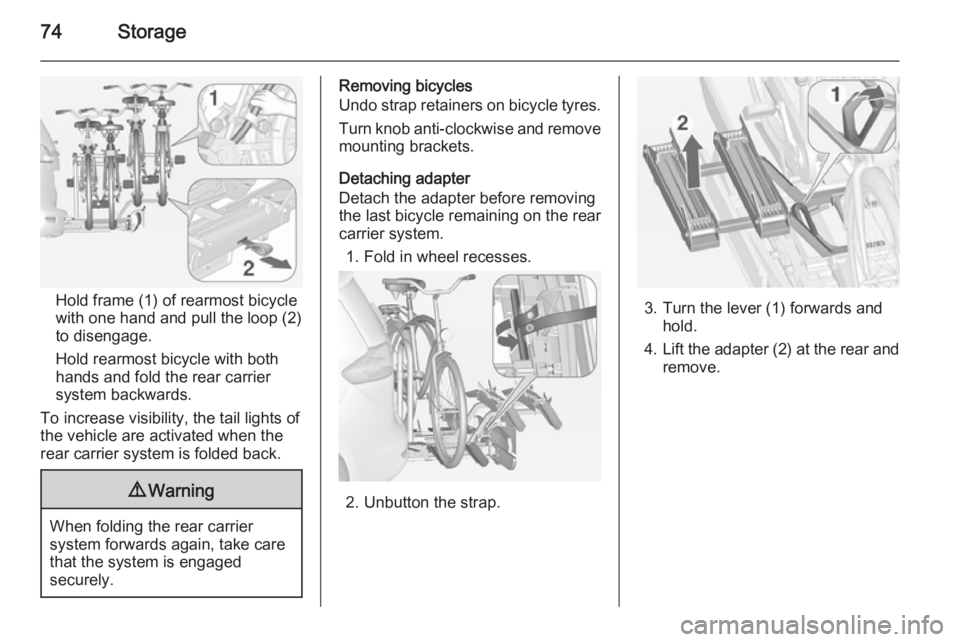
Hold frame (1) of rearmost bicyclewith one hand and pull the loop (2)
to disengage.
Hold rearmost bicycle with both
hands and fold the rear carrier
system backwards.
To increase visibility, the tail lights of
the vehicle are activated when the
rear carrier system is folded back.
9 Warning
When folding the rear carrier
system forwards again, take care
that the system is engaged
securely.
Removing bicycles
Undo strap retainers on bicycle tyres.
Turn knob anti-clockwise and remove
mounting brackets.
Detaching adapter
Detach the adapter before removing
the last bicycle remaining on the rear
carrier system.
1. Fold in wheel recesses.
2. Unbutton the strap.
3. Turn the lever (1) forwards and hold.
4. Lift the adapter (2) at the rear and
remove.
Page 90 of 299
88Storage
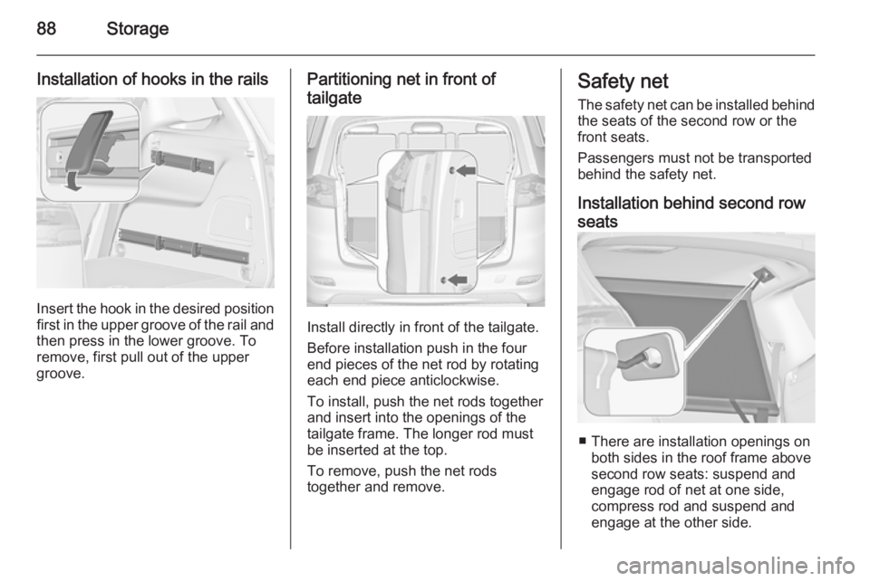
Installation of hooks in the rails
Insert the hook in the desired positionfirst in the upper groove of the rail and
then press in the lower groove. To
remove, first pull out of the upper
groove.
Partitioning net in front of
tailgate
Install directly in front of the tailgate.
Before installation push in the four
end pieces of the net rod by rotating
each end piece anticlockwise.
To install, push the net rods together
and insert into the openings of the
tailgate frame. The longer rod must
be inserted at the top.
To remove, push the net rods
together and remove.
Safety net
The safety net can be installed behind the seats of the second row or the
front seats.
Passengers must not be transported
behind the safety net.
Installation behind second row
seats
■ There are installation openings on both sides in the roof frame above
second row seats: suspend and
engage rod of net at one side,
compress rod and suspend and
engage at the other side.
Page 101 of 299
Instruments and controls99
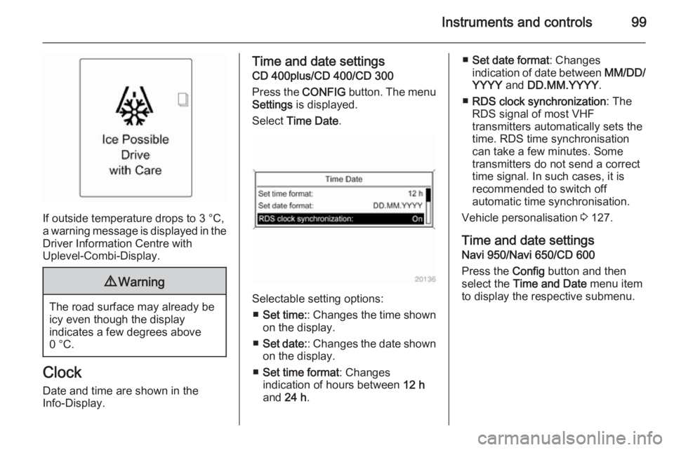
If outside temperature drops to 3 °C,
a warning message is displayed in the Driver Information Centre with
Uplevel-Combi-Display.
9 Warning
The road surface may already be
icy even though the display
indicates a few degrees above
0 °C.
Clock
Date and time are shown in the
Info-Display.
Time and date settings
CD 400plus/CD 400/CD 300
Press the CONFIG button. The menu
Settings is displayed.
Select Time Date .
Selectable setting options:
■ Set time: : Changes the time shown
on the display.
■ Set date: : Changes the date shown
on the display.
■ Set time format : Changes
indication of hours between 12 h
and 24 h.
■Set date format : Changes
indication of date between MM/DD/
YYYY and DD.MM.YYYY .
■ RDS clock synchronization : The
RDS signal of most VHF
transmitters automatically sets the
time. RDS time synchronisation
can take a few minutes. Some
transmitters do not send a correct
time signal. In such cases, it is
recommended to switch off
automatic time synchronisation.
Vehicle personalisation 3 127.
Time and date settings
Navi 950/Navi 650/CD 600
Press the Config button and then
select the Time and Date menu item
to display the respective submenu.
Page 130 of 299
128Instruments and controls
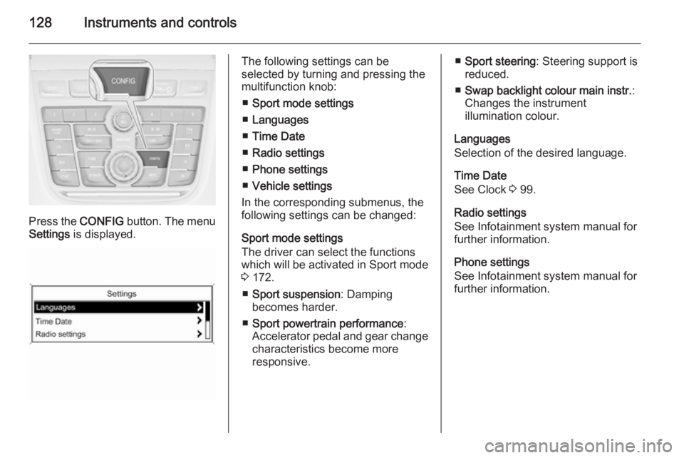
Press the CONFIG button. The menu
Settings is displayed.
The following settings can be
selected by turning and pressing the
multifunction knob:
■ Sport mode settings
■ Languages
■ Time Date
■ Radio settings
■ Phone settings
■ Vehicle settings
In the corresponding submenus, the
following settings can be changed:
Sport mode settings
The driver can select the functions
which will be activated in Sport mode
3 172.
■ Sport suspension : Damping
becomes harder.
■ Sport powertrain performance :
Accelerator pedal and gear change
characteristics become more
responsive.■ Sport steering : Steering support is
reduced.
■ Swap backlight colour main instr. :
Changes the instrument
illumination colour.
Languages
Selection of the desired language.
Time Date
See Clock 3 99.
Radio settings
See Infotainment system manual for further information.
Phone settings
See Infotainment system manual for
further information.
Page 166 of 299
164Driving and operating
8. Unscrew the hose from the fillerneck.
9. Mount the protective cap and turn
clockwise until it engages.
Note
Dispose of AdBlue canister and
hose according to environmental requirements.
Exchanging AdBlue
If less than 5 litres of AdBlue have
been refilled during the last 2 years,
the remaining fluid should be
exchanged since AdBlue has a
limited durability.Caution
Disregard could lead to damage to
the selective catalytic reduction
system.
Automatic transmission
The automatic transmission permits
automatic gearshifting (automatic
mode) or manual gearshifting
(manual mode).
Transmission display
The mode or selected gear is shown
in the transmission display.
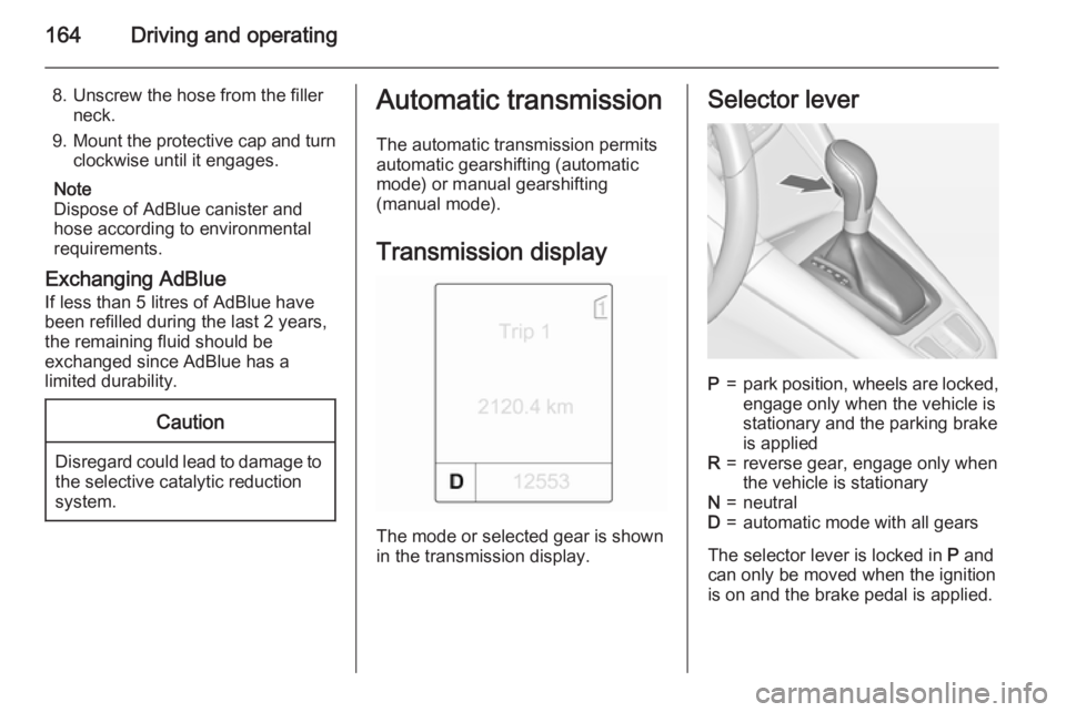
Selector leverP=park position, wheels are locked, engage only when the vehicle is
stationary and the parking brake
is appliedR=reverse gear, engage only when
the vehicle is stationaryN=neutralD=automatic mode with all gears
The selector lever is locked in P and
can only be moved when the ignition is on and the brake pedal is applied.
Page 210 of 299
208Driving and operating
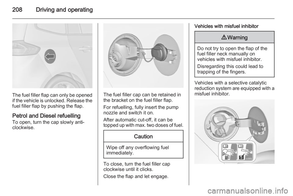
The fuel filler flap can only be opened
if the vehicle is unlocked. Release the
fuel filler flap by pushing the flap.
Petrol and Diesel refuelling
To open, turn the cap slowly anti-
clockwise.The fuel filler cap can be retained in
the bracket on the fuel filler flap.
For refuelling, fully insert the pump
nozzle and switch it on.
After automatic cut-off, it can be
topped up with max. two doses of fuel.
Caution
Wipe off any overflowing fuel
immediately.
To close, turn the fuel filler cap
clockwise until it clicks.
Close the flap and let engage.
Vehicles with misfuel inhibitor9 Warning
Do not try to open the flap of the
fuel filler neck manually on
vehicles with misfuel inhibitor.
Disregarding this could lead to
trapping of the fingers.
Vehicles with a selective catalytic
reduction system are equipped with a
misfuel inhibitor.
Page 211 of 299
Driving and operating209
The misfuel inhibitor ensures that theflap of the fuel filler neck can only be
opened by using a nozzle for diesel
fuel or a funnel for emergency
refilling.
Turn the fuel filler cap slowly anti-
clockwise.
The cap can be retained in the
bracket on the fuel filler flap.
Place the nozzle in straight position to
the filler neck and press with slight
force to insert.
In case of an emergency refilling with a canister, a funnel must be used to
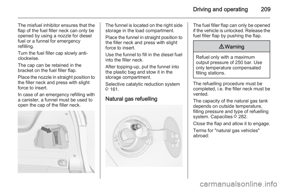
open the cap of the filler neck.The funnel is located on the right side storage in the load compartment.
Place the funnel in straight position to
the filler neck and press with slight
force to insert.
Use the funnel to fill in the diesel fuel
into the filler neck.
After topping-up, put the funnel into
the plastic bag and stow it in the
storage compartment.
Selective catalytic reduction system
3 161.
Natural gas refuellingThe fuel filler flap can only be opened
if the vehicle is unlocked. Release the
fuel filler flap by pushing the flap.9 Warning
Refuel only with a maximum
output pressure of 250 bar. Use
only temperature compensated
filling stations.
The refuelling procedure must be
completed, i.e. the filler neck must be
vented.
The capacity of the natural gas tank depends on outside temperature,
filling pressure and type of refuelling
system. Capacities 3 282.
Close the flap and allow it to engage. Terms for "natural gas vehicles"
abroad:
Page 218 of 299
216Driving and operating
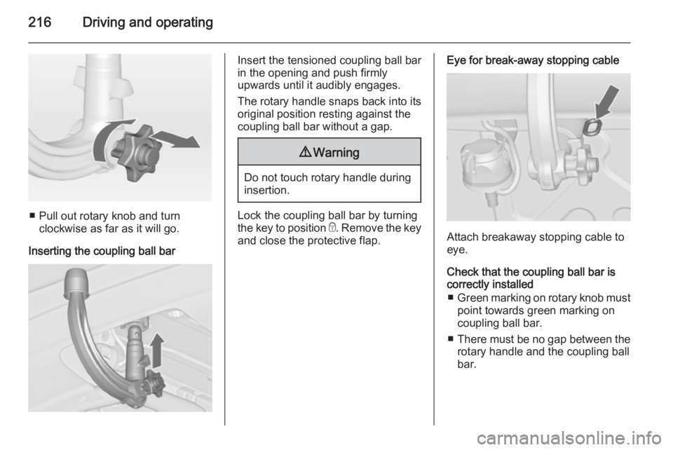
■ Pull out rotary knob and turnclockwise as far as it will go.
Inserting the coupling ball bar
Insert the tensioned coupling ball bar
in the opening and push firmly
upwards until it audibly engages.
The rotary handle snaps back into its
original position resting against the
coupling ball bar without a gap.9 Warning
Do not touch rotary handle during
insertion.
Lock the coupling ball bar by turning
the key to position e. Remove the key
and close the protective flap.
Eye for break-away stopping cable
Attach breakaway stopping cable to
eye.
Check that the coupling ball bar is correctly installed
■ Green marking on rotary knob must
point towards green marking on
coupling ball bar.
■ There must be no gap between the
rotary handle and the coupling ball
bar.
Page 219 of 299
Driving and operating217
■The coupling ball bar must be firmly
engaged in the opening.
■ The coupling ball bar must be locked and the key removed.9 Warning
Towing a trailer is permitted only
when a coupling ball bar is fitted correctly. If the coupling ball bardoes not engage correctly, seekthe assistance of a workshop.
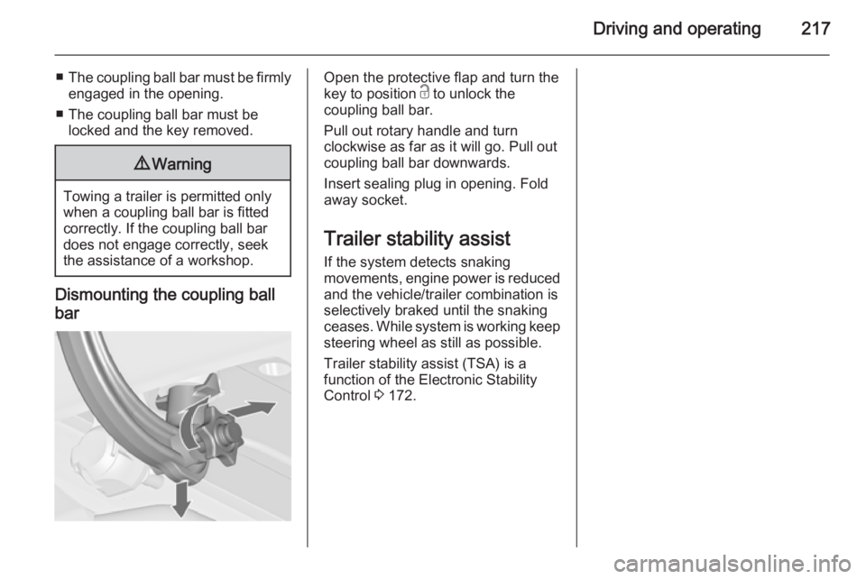
Dismounting the coupling ball
bar
Open the protective flap and turn the
key to position c to unlock the
coupling ball bar.
Pull out rotary handle and turn
clockwise as far as it will go. Pull out coupling ball bar downwards.
Insert sealing plug in opening. Fold away socket.
Trailer stability assist If the system detects snaking
movements, engine power is reduced
and the vehicle/trailer combination is
selectively braked until the snaking ceases. While system is working keep steering wheel as still as possible.
Trailer stability assist (TSA) is a
function of the Electronic Stability
Control 3 172.