Peugeot 308 2015.5 Owner's Manual - RHD (UK, Australia)
Manufacturer: PEUGEOT, Model Year: 2015.5, Model line: 308, Model: Peugeot 308 2015.5Pages: 396, PDF Size: 10.06 MB
Page 251 of 396
249
Checking tyre pressures /
inflating accessories
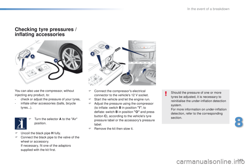
You can also use the compressor, without
injecting any product, to:
-
c
heck or adjust the pressure of your tyres,
-
i
nflate other accessories (balls, bicycle
tyres...).
F
t
u
rn the selector A to the "Air"
position. F
C onnect the compressor's electrical
connector to the vehicle's 12 V socket.
F
S
tart the vehicle and let the engine run.
F
A
djust the pressure using the compressor
(to inflate: switch B in position "I" ; to
deflate: switch B in position "O" and press
button C ), according to the vehicle's tyre
pressure label or the accessory's pressure
label.
F
R
emove the kit then stow it.Should the pressure of one or more
tyres be adjusted, it is necessary to
reinitialise the under-inflation detection
system.
For more information on under-inflation
detection, refer to the corresponding
section.
F
u
n
coil the black pipe H fully.
F
C
onnect the black pipe to the valve of the
wheel or accessory.
I
f necessary, fit one of the adaptors
supplied with the kit first.
8
In the event of a breakdown
Page 252 of 396
250
Changing a wheel
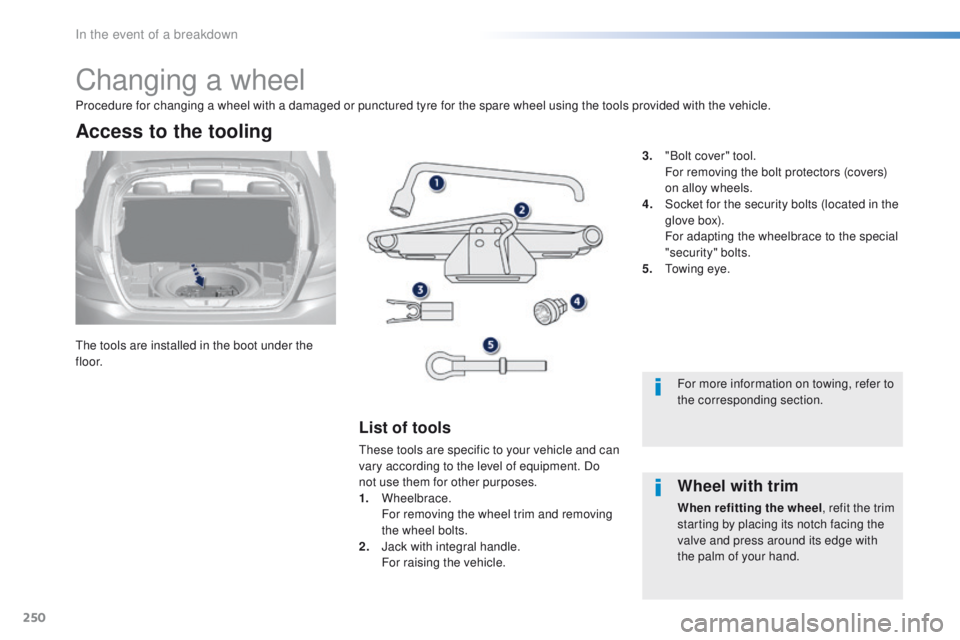
the tools are installed in the boot under the
f l o o r.
Access to the tooling
List of tools
these tools are specific to your vehicle and can
vary according to the level of equipment. Do
not use them for other purposes.
1.
Wheelbrace.
F
or removing the wheel trim and removing
the wheel bolts.
2.
J
ack with integral handle.
F
or raising the vehicle. 3.
"
Bolt cover" tool.
F
or removing the bolt protectors (covers)
on alloy wheels.
4.
S
ocket for the security bolts (located in the
glove box).
F
or adapting the wheelbrace to the special
"security" bolts.
5.
t
o
wing eye.
Procedure for changing a wheel with a damaged or punctured tyre for the spare wheel using the tools provided with the vehicle.
For more information on towing, refer to
the corresponding section.
Wheel with trim
When refitting the wheel, refit the trim
starting by placing its notch facing the
valve and press around its edge with
the palm of your hand.
In the event of a breakdown
Page 253 of 396
251
Taking out the wheel
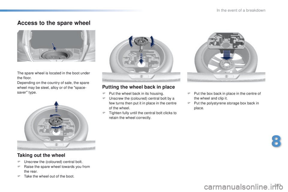
F unscrew the (coloured) central bolt.
F R aise the spare wheel towards you from
the rear.
F
t
a
ke the wheel out of the boot.
Access to the spare wheel
the spare wheel is located in the boot under
t h e f l o o r.
Depending on the country of sale, the spare
wheel may be steel, alloy or of the "space-
saver" type.
Putting the wheel back in place
F Put the wheel back in its housing.
F un screw the (coloured) central bolt by a
few turns then put it in place in the centre
of the wheel.
F
t
i
ghten fully until the central bolt clicks to
retain the wheel correctly. F
P ut the box back in place in the centre of
the wheel and clip it.
F
P
ut the polystyrene storage box back in
place.
8
In the event of a breakdown
Page 254 of 396
252
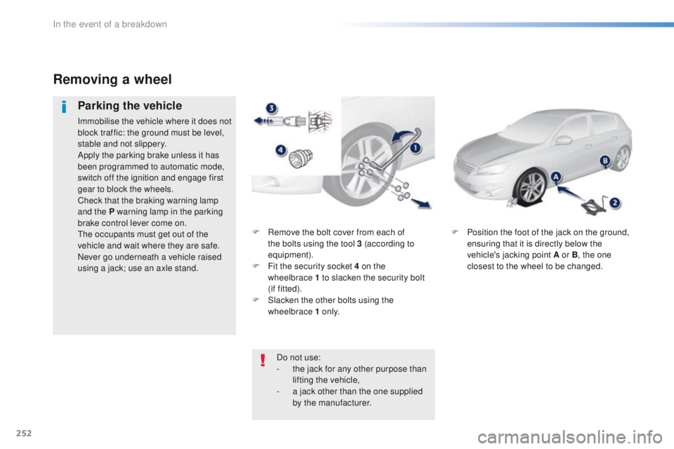
F Remove the bolt cover from each of the bolts using the tool 3 (according to
equipment).
F
F
it the security socket 4 on the
wheelbrace
1 to slacken the security bolt
(if
fitted).
F
S
lacken the other bolts using the
wheelbrace 1 o n l y. F
P osition the foot of the jack on the ground,
ensuring that it is directly below the
vehicle's jacking point A or B , the one
closest to the wheel to be changed.
Removing a wheel
Parking the vehicle
Immobilise the vehicle where it does not
block traffic: the ground must be level,
stable and not slippery.
Apply the parking brake unless it has
been programmed to automatic mode,
switch off the ignition and engage first
gear to block the wheels.
Check that the braking warning lamp
and the P warning lamp in the parking
brake control lever come on.
th
e occupants must get out of the
vehicle and wait where they are safe.
Never go underneath a vehicle raised
using a jack; use an axle stand.
Do not use:
-
t
he jack for any other purpose than
lifting the vehicle,
-
a j
ack other than the one supplied
by the manufacturer.
In the event of a breakdown
Page 255 of 396
253
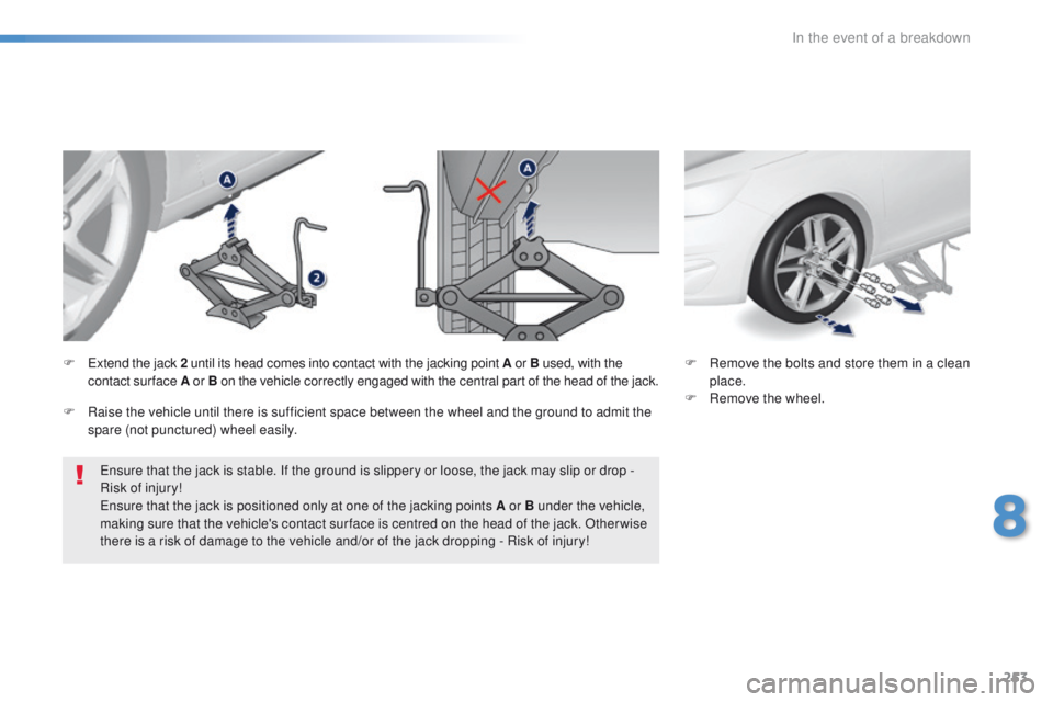
ensure that the jack is stable. If the ground is slippery or loose, the jack may slip or drop -
Risk of injury!
en
sure that the jack is positioned only at one of the jacking points A or B under the vehicle,
making sure that the vehicle's contact sur face is centred on the head of the jack. Other wise
there is a risk of damage to the vehicle and/or of the jack dropping - Risk of injury! F
R
emove the bolts and store them in a clean
place.
F
R
emove the wheel.
F
e
x
tend the jack 2
until its head comes into contact with the jacking point A or B used, with the
contact sur face A or B on the vehicle correctly engaged with the central part of the head of the jack.
F
Ra
ise the vehicle until there is sufficient space between the wheel and the ground to admit the
spare (not punctured) wheel easily.
8
In the event of a breakdown
Page 256 of 396
254
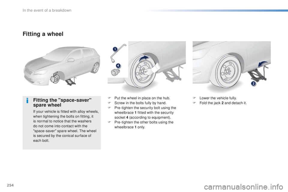
Fitting a wheel
Fitting the "space-saver"
spare wheel
If your vehicle is fitted with alloy wheels,
when tightening the bolts on fitting, it
is normal to notice that the washers
do not come into contact with the
"space-saver" spare wheel. t
h
e wheel
is secured by the conical sur face of
each bolt. F
P
ut the wheel in place on the hub.
F
S
crew in the bolts fully by hand.
F P re-tighten the security bolt using the
wheelbrace 1 fitted with the security
socket 4 (according to equipment).
F
P
re-tighten the other bolts using the
wheelbrace 1 o n l y. F
L
ower the vehicle fully.
F
F
old the jack 2 and detach it.
In the event of a breakdown
Page 257 of 396
255
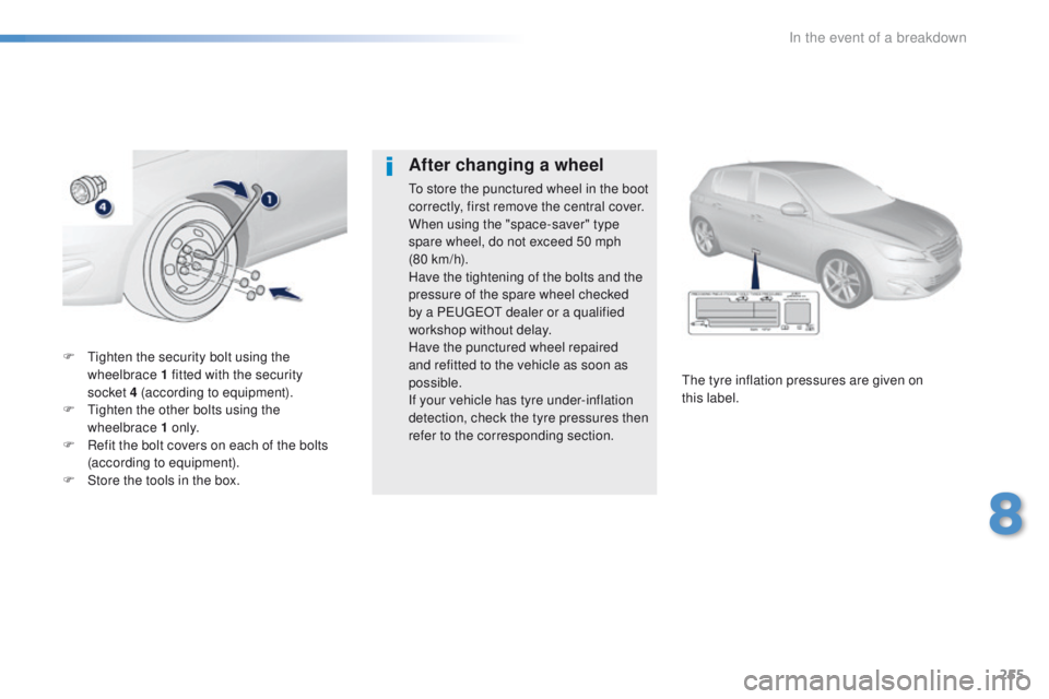
F tighten the security bolt using the wheelbrace 1 fitted with the security
socket
4 (according to equipment).
F
t
i
ghten the other bolts using the
wheelbrace 1 o n l y.
F
R
efit the bolt covers on each of the bolts
(according to equipment).
F
S
tore the tools in the box.
th
e tyre inflation pressures are given on
this
label.
After changing a wheel
to store the punctured wheel in the boot
correctly, first remove the central cover.
When using the "space-saver" type
spare wheel, do not exceed 50 mph
(80
km/h).
Have the tightening of the bolts and the
pressure of the spare wheel checked
by a P
e
uge
Ot
dealer or a qualified
workshop without delay.
Have the punctured wheel repaired
and refitted to the vehicle as soon as
possible.
If your vehicle has tyre under-inflation
detection, check the tyre pressures then
refer to the corresponding section.
8
In the event of a breakdown
Page 258 of 396
256
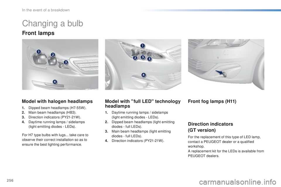
Changing a bulb
Front lamps
Model with "full LED" technology
headlamps
1. Daytime running lamps / sidelamps (light emitting diodes - LeD s).
2.
D
ipped beam headlamps (light emitting
diodes - full L
eD
s).
3.
M
ain beam headlamps (light emitting
diodes - full L
eD
s).
4.
D
irection indicators (PY21-21W).
Model with halogen headlamps
1. Dipped beam headlamps (H7-55W).
2. M ain beam headlamps (HB3).
3.
D
irection indicators (PY21-21W).
4.
D
aytime running lamps / sidelamps
(light emitting diodes - L
eD
s).
For H7 type bulbs with lugs... take care to
observe their correct installation so as to
ensure the best lighting performance.
Front fog lamps (H11)
Direction indicators
(GT version)
For the replacement of this type of LeD l amp,
contact a Pe ugeOt dealer or a qualified
workshop.
A replacement kit for the L
eD
s is available from
P
e
uge
Ot d
ealers.
In the event of a breakdown
Page 259 of 396
257
In some weather conditions (e.g. low
temperature or humidity), the presence
of misting on the internal sur face of the
glass of the headlamps and rear lamps
is normal; it disappears after the lamps
have been on for a few minutes.th
e headlamps are fitted with
polycarbonate glass with a protective
coating:
F
d
o not clean them using a dr y
or abrasive cloth, nor with a
detergent or solvent product,
F
u
se a sponge and soapy water or a
pH neutral product,
F
w
hen using a high pressure washer
on persistent marks, do not keep
the lance directed towards the
lamps or their edges for too long,
so as not to damage their protective
coating and seals.
Changing a bulb should only be done
after the headlamp has been switched
off for several minutes (risk of serious
burns).
F
D
o not touch the bulb directly with
your fingers, use a lint-free cloth.
It is imperative to use only anti-
ultraviolet (
uV
) type bulbs to avoid
damaging the headlamp.
Always replace a failed bulb with a
new bulb with the same type and
specification.
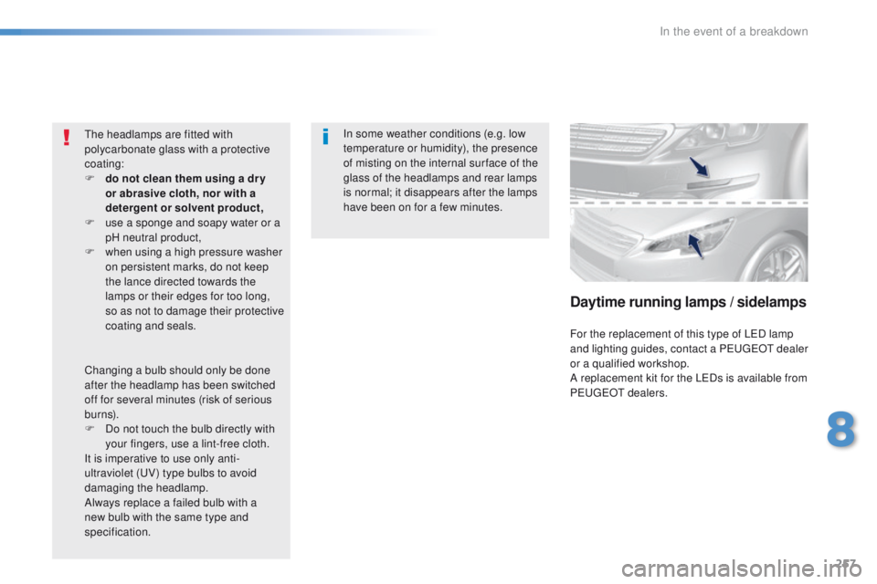
Daytime running lamps / sidelamps
For the replacement of this type of LeD l amp
and lighting guides, contact a Pe ugeOt dealer
or a qualified workshop.
A replacement kit for the L
eD
s is available from
P
e
uge
Ot d
ealers.
8
In the event of a breakdown
Page 260 of 396
258
Main beam headlamps
(halogen model)
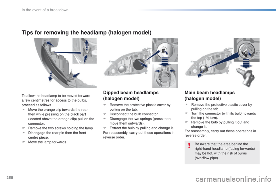
F Remove the protective plastic cover by pulling on the tab.
F
t
u
rn the connector (with its bulb) towards
the top (1/4 turn).
F
R
emove the bulb by pulling it out and
change it.
For reassembly, carry out these operations in
reverse order.
Dipped beam headlamps
(halogen model)
F Remove the protective plastic cover by
pulling on the tab.
F
D
isconnect the bulb connector.
F
D
isengage the two springs (press then
move them outwards).
F
e
x
tract the bulb by pulling and change it.
For reassembly, carry out these operations in
reverse order.
Be aware that the area behind the
right-hand headlamp (facing forwards)
may be hot, with the risk of burns
(over flow
pipe).
to a
llow the headlamp to be moved for ward
a few centimetres for access to the bulbs,
proceed as follows:
F Move the orange clip towards the rear then while pressing on the black part
(located above the orange clip) pull on the
connector.
F
R
emove the two screws holding the lamp.
F
D
isengage the rear pin then the front
centre piece.
F
M
ove the lamp for wards.
Tips for removing the headlamp (halogen model)
In the event of a breakdown