PEUGEOT 308 2018 Owners Manual
Manufacturer: PEUGEOT, Model Year: 2018, Model line: 308, Model: Peugeot 308 2018Pages: 360, PDF Size: 12.38 MB
Page 251 of 360

249
Changing direction indicator
bulbs (on models with halogen
headlamps)
Quicker flashing of the direction indicator
lamp (left or right) indicates the failure of
one of the bulbs on the corresponding
side.
F
T
urn the bulb holder a quarter turn and pull
it out.
F
T
urn the bulb a quarter turn, pull it out and
fit a new bulb.
To refit, carry out these operations in reverse
o r d e r.
Amber colour bulbs, such as the direction
indicators, must be replaced by bulbs
with identical colour and specifications. To refit, close the protective cover very
carefully to guarantee the leak-tightness
of the lamp.
Changing dipped beam headlamp
bulbs (on models with halogen
headlamps)
F Remove the protective cover by pulling the
tongue.
F
P
ull the connector back to disconnect it.
F
P
ull the bulb back to extract it.
F
R
eplace the bulb.
To refit, carry out these operations in reverse
o r d e r.
Changing main beam headlamp
bulbs (on models with halogen
headlamps)
F Remove the protective cover by pulling the tongue.
F
T
urn the bulb holder a quarter turn and pull
it out.
F
P
ull the bulb out and replace it.
To refit, carry out these operations in reverse
o r d e r.
8
In the event of a breakdown
Page 252 of 360
250
To replace this type of bulb, you can also
contact a PEUGEOT dealer or a qualified
workshop.
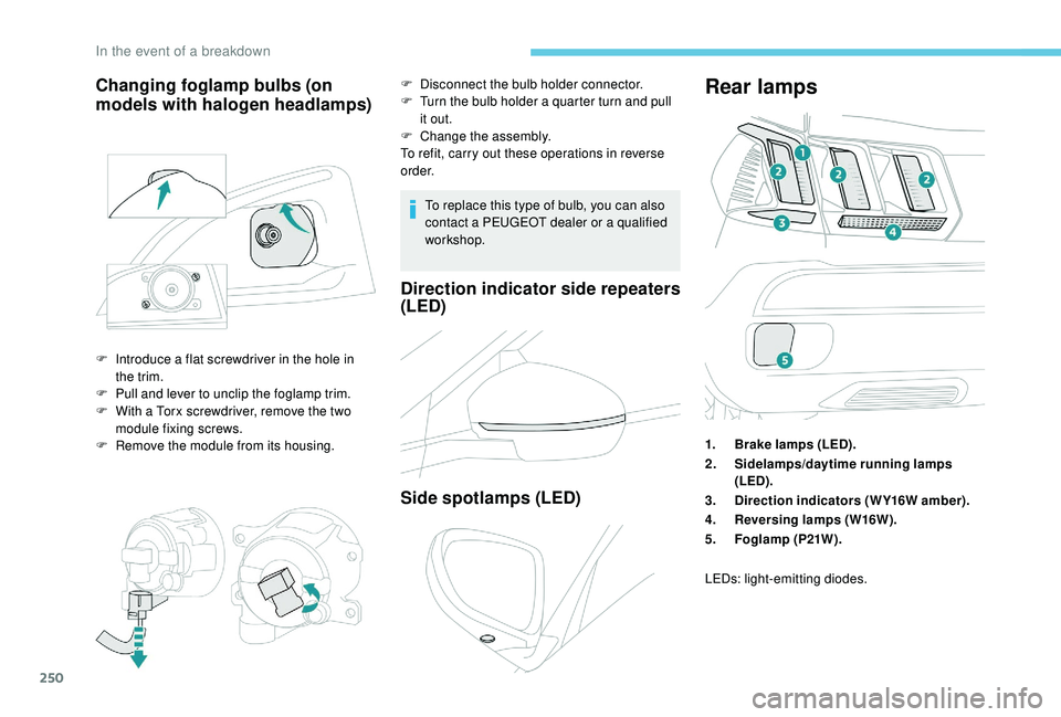
Direction indicator side repeaters
(LED)
Side spotlamps (LED)
Rear lamps
1.Brake lamps (LED).
2. Sidelamps/daytime running lamps
(LED).
3. Direction indicators (WY16W amber).
4. Reversing lamps (W16W).
5. Foglamp (P21W).
Changing foglamp bulbs (on
models with halogen headlamps)
F Introduce a flat screwdriver in the hole in
the trim.
F
P
ull and lever to unclip the foglamp trim.
F
W
ith a Torx screwdriver, remove the two
module fixing screws.
F
R
emove the module from its housing. F
D
isconnect the bulb holder connector.
F
T
urn the bulb holder a quarter turn and pull
it out.
F
C
hange the assembly.
To refit, carry out these operations in reverse
o r d e r.
LEDs: light-emitting diodes.
In the event of a breakdown
Page 253 of 360
251
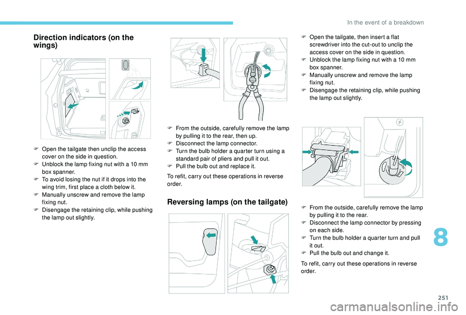
Direction indicators (on the
wings)
To refit, carry out these operations in reverse
o r d e r.
Reversing lamps (on the tailgate)
To refit, carry out these operations in reverse
o r d e r.
F
O
pen the tailgate then unclip the access
cover on the side in question.
F
U
nblock the lamp fixing nut with a 10
mm
box spanner.
F
T
o avoid losing the nut if it drops into the
wing trim, first place a cloth below it.
F
M
anually unscrew and remove the lamp
fixing nut.
F
D
isengage the retaining clip, while pushing
the lamp out slightly. F
F
rom the outside, carefully remove the lamp
by pulling it to the rear, then up.
F
D
isconnect the lamp connector.
F
T
urn the bulb holder a quarter turn using a
standard pair of pliers and pull it out.
F
P
ull the bulb out and replace it. F
O
pen the tailgate, then insert a flat
screwdriver into the cut-out to unclip the
access cover on the side in question.
F
U
nblock the lamp fixing nut with a 10 mm
box spanner.
F
M
anually unscrew and remove the lamp
fixing nut.
F
D
isengage the retaining clip, while pushing
the lamp out slightly.
F
F
rom the outside, carefully remove the lamp
by pulling it to the rear.
F
D
isconnect the lamp connector by pressing
on each side.
F
T
urn the bulb holder a quarter turn and pull
it out.
F
P
ull the bulb out and change it.
8
In the event of a breakdown
Page 254 of 360

252
If changing a bulb within a few minutes
of switching off the ignition, take care not
to touch the exhaust – there is a risk of
burns!
Third brake lamp (LED)
Licence plate lamps
F Insert a thin screwdriver into the slot in the lens.
F
P
ush it out to unclip it.
F
R
emove the lens.
F
P
ull the bulb out and change it.
Changing a wiper blade
Before removing a front
wiper
Removing
F Lift the corresponding wiper arm away from the windscreen.
F
U
nclip and remove the wiper blade.
Refitting
F Position and clip the new wiper blade to the arm.
F
C
arefully lower the wiper arm.
Foglamps
These bulbs are replaced from outside the rear
bumper:
F
P
ass your hand under the bumper,
F
T
urn the bulb holder a quarter turn and
remove it,
F
T
urn the bulb a quarter turn, pull it out and
change it.
To refit, carry out these operations in reverse
o r d e r. F
W
ithin one minute after switching off the
ignition, operate the wiper control stalk to
position the wiper blades in the middle of
the windscreen (maintenance position).
In the event of a breakdown
Page 255 of 360
253
After refitting a front wiper
F Switch on the ignition.
F O perate the wiper control stalk again to
park the wiper blades.
Changing a fuse
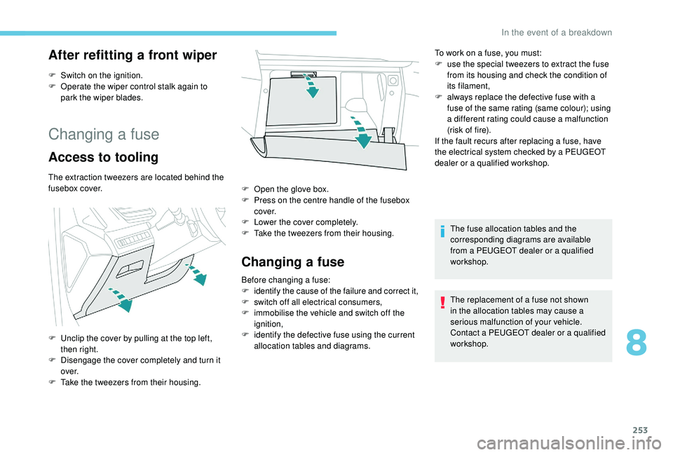
Access to tooling
The extraction tweezers are located behind the
fusebox cover.
F
U
nclip the cover by pulling at the top left,
then right.
F
D
isengage the cover completely and turn it
ove r.
F
T
ake the tweezers from their housing. F
O
pen the glove box.
F
P
ress on the centre handle of the fusebox
c ove r.
F
L
ower the cover completely.
F
T
ake the tweezers from their housing.
Changing a fuse
Before changing a fuse:
F identify the cause of the failure and correct it,
F
s
witch off all electrical consumers,
F
i
mmobilise the vehicle and switch off the
ignition,
F
i
dentify the defective fuse using the current
allocation tables and diagrams. To work on a fuse, you must:
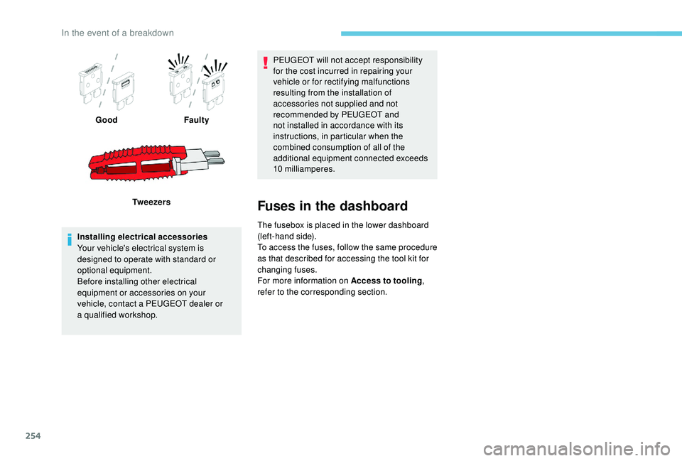
F
u
se the special tweezers to extract the fuse
from its housing and check the condition of
its filament,
F
a
lways replace the defective fuse with a
fuse of the same rating (same colour); using
a different rating could cause a malfunction
(risk of fire).
If the fault recurs after replacing a fuse, have
the electrical system checked by a PEUGEOT
dealer or a qualified workshop.
The fuse allocation tables and the
corresponding diagrams are available
from a PEUGEOT dealer or a qualified
workshop.
The replacement of a fuse not shown
in the allocation tables may cause a
serious malfunction of your vehicle.
Contact a PEUGEOT dealer or a qualified
workshop.
8
In the event of a breakdown
Page 256 of 360
254
GoodFaulty
Tw e e z e r s
Installing electrical accessories
Your vehicle's electrical system is
designed to operate with standard or
optional equipment.
Before installing other electrical
equipment or accessories on your
vehicle, contact a PEUGEOT dealer or
a
qualified workshop. PEUGEOT will not accept responsibility
for the cost incurred in repairing your
vehicle or for rectifying malfunctions
resulting from the installation of
accessories not supplied and not
recommended by PEUGEOT and
not installed in accordance with its
instructions, in particular when the
combined consumption of all of the
additional equipment connected exceeds
10
milliamperes.
Fuses in the dashboard
The fusebox is placed in the lower dashboard
(left-hand side).
To access the fuses, follow the same procedure
as that described for accessing the tool kit for
changing fuses.
For more information on Access to tooling,
refer to the corresponding section.
In the event of a breakdown
Page 257 of 360
255
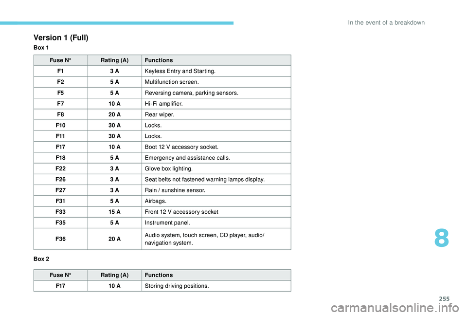
Version 1 (Full)
Box 1Fuse N° Rating (A) Functions
F1 3
A
K
eyless Entry and Starting.
F2 5
AMultifunction screen.
F5 5
AReversing camera, parking sensors.
F7 10
AHi-Fi amplifier.
F8 20
ARear wiper.
F10 30
ALocks.
F11 30
ALocks.
F17 10
ABoot 12
V accessory socket.
F18 5
AEmergency and assistance calls.
F22 3
AGlove box lighting.
F26 3
ASeat belts not fastened warning lamps display.
F27 3
ARain / sunshine sensor.
F31 5
AAirbags.
F33 15
AFront 12
V accessory socket
F35 5
AInstrument panel.
F36 20
AAudio system, touch screen, CD player, audio/
navigation system.
Fuse N° Rating (A) Functions
F17 10
AStoring driving positions.
Box 2
8
In the event of a breakdown
Page 258 of 360
256
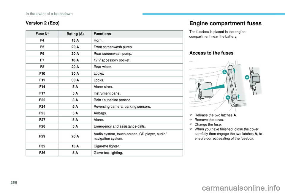
Version 2 (Eco)
Fuse N°Rating (A) Functions
F4 15
AHorn.
F5 20
AFront screenwash pump.
F6 20
ARear screenwash pump.
F7 10
A12
V accessory socket.
F8 20
ARear wiper.
F10 30
ALocks.
F11 30
ALocks.
F14 5
AAlarm siren.
F17 5
AInstrument panel.
F22 3
ARain / sunshine sensor.
F24 5
AReversing camera, parking sensors.
F25 5
AAirbags.
F27 5
AAlarm.
F28 5
AEmergency and assistance calls.
F29 20
AAudio system, touch screen, CD player, audio/
navigation system.
F32 15
ACigarette lighter.
F36 5
AGlove box lighting.
Engine compartment fuses
The fusebox is placed in the engine
compartment near the battery.
Access to the fuses
F Release the two latches A .
F R emove the cover.
F
C
hange the fuse.
F
W
hen you have finished, close the cover
carefully then engage the two latches A , to
ensure correct sealing of the fusebox.
In the event of a breakdown
Page 259 of 360
257
12 V battery
Procedure for starting the engine using another
battery or charging a discharged battery.
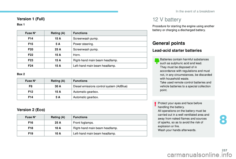
Version 1 (Full)
Fuse N° Rating (A) Functions
F14 15
AScreenwash pump.
F15 5
APower steering.
F20 25
AScreenwash pump.
F22 15
AHorn.
F23 15
ARight-hand main beam headlamp.
F24 15
ALeft-hand main beam headlamp.
Fuse N° Rating (A) Functions
F8 30
ADiesel emissions control system (AdBlue)
F12 15
AAutomatic gearbox.
F14 5
AAutomatic gearbox.
Version 2 (Eco)
Fuse N° Rating (A) Functions
F16 25
AFront foglamps.
F18 10
ARight-hand main beam headlamp.
F19 10
ALeft-hand main beam headlamp.
Box 1
Box 2
General points
Lead-acid starter batteries
Batteries contain harmful substances
such as sulphuric acid and lead.
They must be disposed of in
accordance with regulations and must
not, in any circumstances, be discarded
with household waste.
Take used remote control batteries and
vehicle batteries to a special collection
point.
Protect your eyes and face before
handling the battery.
All operations on the battery must be
carried out in a well ventilated area and
away from naked flames and sources
of sparks, so as to avoid the risk of
explosion or fire.
Wash your hands afterwards.
8
In the event of a breakdown
Page 260 of 360
258
Access to the battery Starting using another battery
When your vehicle's battery is discharged, the
engine can be started using a backup battery
(external or from another vehicle) and jump
leads or using a battery booster.
Never try to start the engine by
connecting a battery charger.
Never use a 24
V or higher battery
b o o s t e r.
Check beforehand that the backup
battery has a nominal voltage of 12
V and
a capacity at least equal to that of the
discharged battery.
The two vehicles must not be in contact
with each other.
Switch off all the electrical consumers
on both vehicles (audio system, wipers,
lighting, etc.).
Make sure that the jump leads are not
close to moving parts of the engine (fan,
belts, etc.).
Do not disconnect the (+) terminal while
the engine is running.
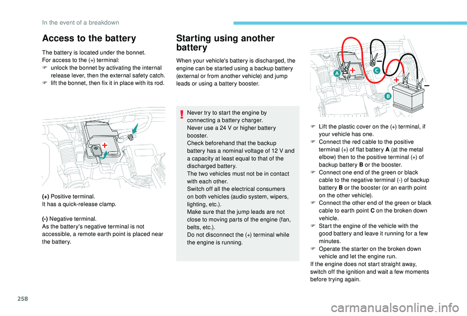
The battery is located under the bonnet.
For access to the (+) terminal:
F
u
nlock the bonnet by activating the internal
release lever, then the external safety catch.
F
l
ift the bonnet, then fix it in place with its rod.
(+) Positive terminal.
It has a quick-release clamp.
(-) Negative terminal.
As the battery's negative terminal is not
accessible, a remote earth point is placed near
the battery. F
L
ift the plastic cover on the (+) terminal, if
your vehicle has one.
F
C
onnect the red cable to the positive
terminal (+) of flat battery A (at the metal
elbow) then to the positive terminal (+) of
backup battery B or the booster.
F
C
onnect one end of the green or black
cable to the negative terminal (-) of backup
battery B or the booster (or an earth point
on the other vehicle).
F
C
onnect the other end of the green or black
cable to earth point C on the broken down
vehicle.
F
S
tart the engine of the vehicle with the
good battery and leave it running for a few
minutes.
F
O
perate the starter on the broken down
vehicle and let the engine run.
If the engine does not start straight away,
switch off the ignition and wait a few moments
before trying again.
In the event of a breakdown