brake Peugeot Bipper 2008.5 User Guide
[x] Cancel search | Manufacturer: PEUGEOT, Model Year: 2008.5, Model line: Bipper, Model: Peugeot Bipper 2008.5Pages: 140, PDF Size: 1.65 MB
Page 92 of 140

86
Driving safety
HANDBRAKE
Applying
Pull the handbrake to immobilise your
vehicle.
Check that the handbrake is applied firmly
before leaving the vehicle. If the handbrake is still on or has
not been released properly, this is
indicated by this warning light which
comes on on the instrument panel.
When parking on a slope, direct your wheels
towards the pavement and pull the handbrake.
There is no advantage in engaging a gear
after parking the vehicle, particularly if the
vehicle is loaded.
Releasing
Pull the handle and press the button to lower
the handbrake.
HAZARD WARNING LIGHTS
Press this button, the two direction
indicators flash.
They operate with the ignition off.
When the hazard warning lights are switched
on, the change of direction function, via the
right-hand or left-hand direction indicator,
is deactivated.
Page 93 of 140

87
5
SAFETY
Driving safety
HORN
Press the centre of the steering wheel.
ABS ANTI-LOCK BRAKING SYSTEM
The ABS increases the stability and
manoeuvrability of your vehicle when
braking, particularly on poor or slippery road
surfaces.
Note: when changing wheels (tyres and
rims), make sure that they conform to the
manufacturer ’s recommendations.
The anti-lock braking system comes into
operation automatically when there is a risk
of wheel lock.
Normal operation of the ABS may make
itself felt by slight vibrations of the brake
pedal.
In emergency braking, press very firmly
without releasing the pressure.
If the ABS warning light on the
instrument panel comes on, this
indicates a malfunction of the
anti-lock braking system which
could result in a loss of control of the vehicle
on braking.
Stop immediately.
Consult a PEUGEOT dealer.
Good practice
The anti-lock braking system comes into
operation automatically when there is a risk
of wheel lock. It does not permit shorter
braking. On very slippery road surfaces
(ice, oil, etc.) the ABS may lengthen the
braking distances. In emergency braking,
do not hesitate to press the brake pedal
firmly, without releasing the pressure, even
on slippery roads, you will then be able to
continue to manoeuvre the vehicle to avoid
an obstacle.
Page 111 of 140
102
Towing a trailer
In certain cases of particularly arduous
use (towing the maximum load up a steep
slope in high temperatures), the engine
automatically limits its power. In this
case, the automatic cutting off of the air
conditioning allows the engine power to be
recovered.
If the coolant temperature
warning light comes on, stop the
vehicle and switch off the engine
as soon as possible.
See the "Levels" section of chapter 7.
Tyres: check the tyre pressures of the
towing vehicle (see the "Identification
features" section of chapter 7) and of
the trailer, observing the recommended
pressure.
Brakes: towing increases the braking
distance. Drive at a moderate speed,
change down early and brake gradually.
Side wind: sensitivity to side wind is
increased. Drive smoothly and at a
moderate speed.
ABS: the system only controls the vehicle,
not the trailer.
Rear parking assistance: the
assistance will be deactivated
automatically when an original PEUGEOT
towbar is used (see the "Rear parking
assistance" section of chapter 4).
Towbar
We recommend the use of original
PEUGEOT towbars and their harnesses,
which have been tested and approved from
the design stage of your vehicle, and that
the fitting of this equipment is entrusted to a
PEUGEOT dealer .
If this equipment is not fitted by a PEUGEOT
dealer , it is essential that it is fitted using
the electrical pre-equipment located at the
rear of the vehicle in accordance with the
manufacturer ’s instructions.
The operation of the sensors is deactivated
automatically when the pin of the trailer
cable is inserted in the towbar socket.
When the trailer cable pin is removed, the
sensors are re-activated.
Distribution of loads
Dis t r ibut e t he load in t he t r ailer s o t hat t he
heav ies t objec t s ar e as c los e as pos s ible
t o t he ax le and t he nos e weight is c los e
t o t he max imum aut hor is ed wit hout ,
howev er, ex c eeding it . T he air dens it y
dec r eas es wit h alt it ude, s o r educ ing t he
per f or manc e of t he engine. T he max imum
t owed load mus t be r educ ed by 10 % f or
eac h 1 000 met r es of alt it ude. Ref er t o
t he " Tec hnic al dat a" c hapt er f or det ails of
t he weight s and t owed loads applic able t o
y our v ehic le and als o t o t he adminis t r at iv e
doc ument s ( V5 r egis t r at ion doc ument , . . . ) .
Page 117 of 140
107
7
TROUBLESHOOTING
Changing a wheel
CHANGING A WHEEL
Parking the vehicle
As far as possible, park the vehicle on level,
stable and non-slippery ground.
Apply the handbrake, switch off the ignition
and engage first gear (on a hill).
If possible, place a chock under the
wheel diagonally opposite the wheel to be
changed.
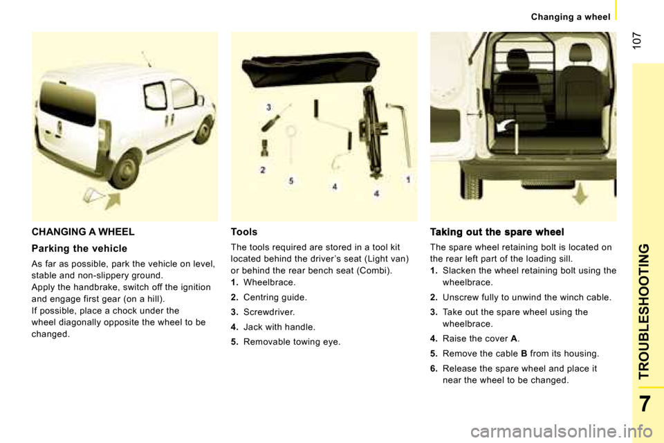
Tools
The tools required are stored in a tool kit
located behind the driver ’s seat (Light van)
or behind the rear bench seat (Combi).
1. Wheelbrace.
2. Centring guide.
3. Screwdriver.
4. Jack with handle.
5. Removable towing eye. The spare wheel retaining bolt is located on
the rear left part of the loading sill.
1. Slacken the wheel retaining bolt using the
wheelbrace.
2. Unscrew fully to unwind the winch cable.
3. Take out the spare wheel using the
wheelbrace.
4. Raise the cover A .
5. Remove the cable B from its housing.
6. Release the spare wheel and place it
near the wheel to be changed.
Page 118 of 140

108
Changing a wheel
Removing
1. Park the vehicle on level, stable and non-
slippery ground. Apply the handbrake.
Switch off the ignition and engage first
gear or reverse, depending on the slope.
2. Detach the trim (large model) using
the wheelbrace 1 , pulling at the valve
passage.
Slide the screwdriver 3 into the notch on
the trim (small model) and use the tool as
a lever, pressing to unclip the trim.
3. Slacken the wheel bolts using the
wheelbrace.
4. Position the jack underneath the body,
in accordance with the illustration, at
the mark A (in the side member recess)
as close as possible to the wheel to be
changed.
5. Extend the jack 4 until its base is in
contact with the ground. Ensure that the
centreline of the jack base is vertical in
relation to the location used.
6. Raise the vehicle.
7. Remove the bolts and detach the wheel.
Putting the wheel back in place
1. Install the support on the wheel.
2. Place the cable B in position.
3. Lower the cover A .
4. Position the wheel.
5. Turn the wheelbrace clockwise to raise
the spare wheel completely.
Page 126 of 140
115
7
TROUBLESHOOTING
Changing a bulb
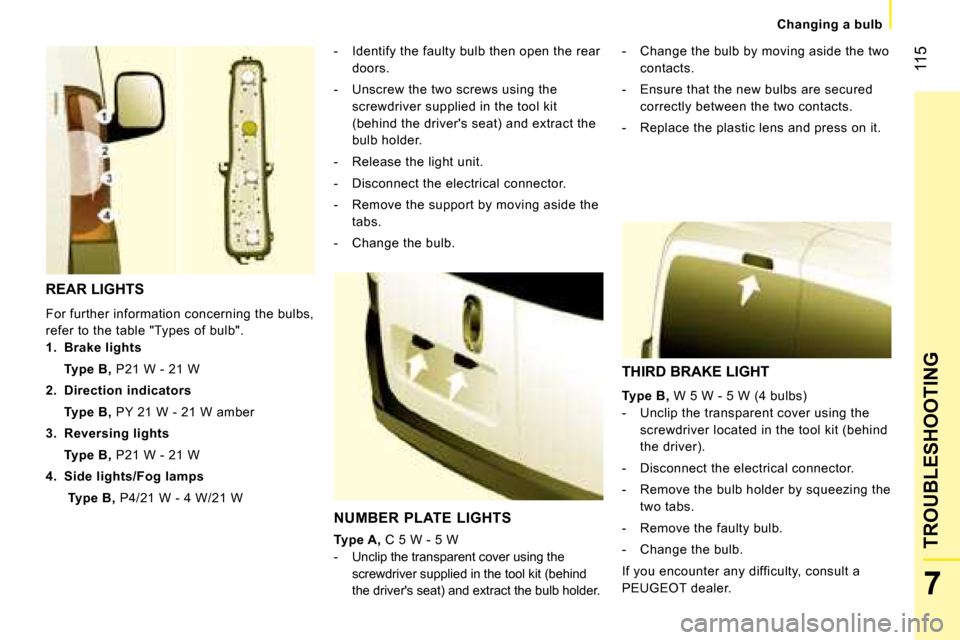
REAR LIGHTS
For further information concerning the bulbs,
refer to the table "Types of bulb".
1. Brake lights
Type B, P21 W - 21 W
2. Direction indicators
Type B, PY 21 W - 21 W amber
3. Reversing lights
Type B, P21 W - 21 W
4. Side lights/Fog lamps
Type B, P4/21 W - 4 W/21 W - Identify the faulty bulb then open the rear
doors.
- Unscrew the two screws using the screwdriver supplied in the tool kit
(behind the driver's seat) and extract the
bulb holder.
- Release the light unit.
- Disconnect the electrical connector.
- Remove the support by moving aside the tabs.
- Change the bulb.
NUMBER PLATE LIGHTS
Type A, C 5 W - 5 W
- Unclip the transparent cover using the screwdriver supplied in the tool kit (behind
the driver's seat) and extract the bulb holder. - Change the bulb by moving aside the two
contacts.
- Ensure that the new bulbs are secured correctly between the two contacts.
- Replace the plastic lens and press on it.
THIRD BRAKE LIGHT
Type B, W 5 W - 5 W (4 bulbs)
- Unclip the transparent cover using the screwdriver located in the tool kit (behind
the driver).
- Disconnect the electrical connector.
- Remove the bulb holder by squeezing the two tabs.
- Remove the faulty bulb.
- Change the bulb.
If you encounter any difficulty, consult a
PEUGEOT dealer.
Page 131 of 140

118
Changing a fuse
DRIVER’S SIDE FASCIA PANEL FUSES
Identifi cation mark
Amperage
Functions
F12 7.5 A Right-hand dipped headlamp supply
F13 7.5 A Left-hand dipped headlamp supply - headlamp height adjuster
F31 5 A Engine control unit supply switch
F32 7.5 A Front light - front courtesy light - rear courtesy light lamp
F36 10 A Audio equipment - mobile telephone pre-equipment - air conditioning control panel - EODB
F37 5 A Brake light - instrument panel
F38 20 A Locking of the doors
F43 15 A Wipers pump
F47 20 A Driver ’s electric window motor supply
F48 20 A Passenger ’s electric window motor supply
F49 5 A Parking assistance control unit - rear lighting sw itch - electric exterior mirrors
F50 7.5 A Air bags control unit
F51 5 A Switch on brake pedal - switch on clutch pedal
F53 5 A Instrument panel - rear fog lamps
Page 136 of 140

125
7
TROUBLESHOOTING
Under the bonnet
Diesel engine
UNDER THE BONNET
4. Brake and clutch fluid reservoir.
5. Air filter.
6. Dipstick.
7. Engine oil filler cap.
8. Power steering fluid reservoir.
1. Windscreen wash reservoir.
2. Fuse box.
3. Engine coolant reservoir.
Page 137 of 140

126
Under the bonnet
Petrol engine
UNDER THE BONNET
4. Brake and clutch fluid reservoir.
5. Air filter.
6. Dipstick.
7. Engine oil filler cap.
8. Power steering fluid reservoir.
1. Windscreen wash reservoir.
2. Fuse box.
3. Engine coolant reservoir.
Page 138 of 140

127
7
TROUBLESHOOTING
Levels
These regular maintenance operations
will keep your vehicle in good
running order. Consult the instructions at
a PEUGEOT dealership or in the servicing
booklet enclosed in the handbook pack.
LEVELS
Oil level
Check the level regularly and top up
between changes. The maximum
consumption is 0.5 l per 600 miles
(1 000 km). Check the level with the vehicle
level, engine cold, using the dipstick.
Dipstick
There are two marks on the
dipstick:
A = maximum
If you fill past this mark,
consult a dealer.
B = minimum
Never allow the level to fall
below this mark.
To maintain the reliability of engines and
emission control systems, the use of
additives in engine oil is prohibited.
Oil change
It is imperative that this is carried out at the
intervals specified and the viscosity grade of
the oil selected must fulfil the requirements
in accordance with the manufacturer ’s
servicing schedule. Consult the instructions
at a PEUGEOT dealership.
Remove the dipstick before filling.
Check the level after filling (never exceed
the maximum mark).
Screw the cap back onto the sump before
closing the bonnet.
Changing the brake fluid
The brake fluid must be changed at
the intervals stated, according to the
manufacturer ’s servicing schedule.
Use fluids recommended by the
manufacturer, which fulfil DOT4 standards.
The level must be between the MIN and
MAX marks on the reservoir.
If fluid has to be added frequently, this
indicates a failure which must be checked by
a PEUGEOT dealer as soon as possible.
Warning lights
Checking by means of the warning
lights on the instrument panel
is described in chapter 1, refer to the
"Instruments and controls" section.