heating Peugeot Partner Tepee 2015 Owner's Manual
[x] Cancel search | Manufacturer: PEUGEOT, Model Year: 2015, Model line: Partner Tepee, Model: Peugeot Partner Tepee 2015Pages: 276, PDF Size: 12.76 MB
Page 4 of 276
2
Partner_2_VP_en_Chap00a_Sommaire_ed02-2014
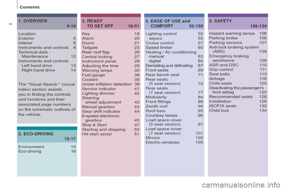
Key 18
Alarm 20
Doors
21tailgate
23
Rear roof flap
26
Central locking
27
Instrument panel
28
Adjusting the time
29
W
arning lamps
30
Fuel gauge
38
Coolant
38
Under-inflation detection
39
Service indicator
41
Lighting dimmer
42
Steering
wheel adjustment
43
Manual gearbox
43g
ear shift indicator
44
6-speed electronic
gearbox
45
Stop & Start
47
Starting and stopping
50
Hill start assist
51Lighting control
52
wipers 55
Cruise control
57
Speed limiter
60
Heating /
Air conditioning
manual
63 digital
65
Demisting and defrosting
6
7
Front seats
69
Rear bench seat
71
Rear seats
(5 seat version)
74
Rear seats
(7 seat version)
77
Modularity
84
Front fittings
86
Zenith roof
90
Roof bars
95
Courtesy lamps
96
Load space cover
(5 seat version)
97
Load space cover
(7 seat version)
101
Mirrors
103e
lectric windows
105
READY
TO SET OFF
3.
18-51 SAFETY
5.
106-134
Locatione
xterior 5
Interior
6
Instruments and controls
8technical data - Maintenance
12
Instruments and controls Left hand drive
13
Right hand drive
14
OVERVIEW
1.
4-14
Hazard warning lamps 106
Parking brake 106
Parking sensors
107
Anti-lock braking system (ABS)
109
e
mergency braking assistance
109
ASR and DSC
1
10
g
rip control
1
11
Seat belts
1
13
Airbags
1
16
Child seats
120
Deactivating the passenger's
front airbag
1
23
Recommended seats
126
Installation
128
ISOFIX seats
132
Child lock
134
EASE OF USE and
COMFORT
4.
52-105
2.
15-17
ECO-DRIVING
environment 15
Eco-driving 16
t
he "Visual Search " (visual
index) section assists
you in finding the controls
and functions and their
associated page numbers
on the schematic outlines of
the vehicle.
Contents
Page 11 of 276
9
Partner_2_VP_en_Chap01_vue-ensemble_ed02-2014
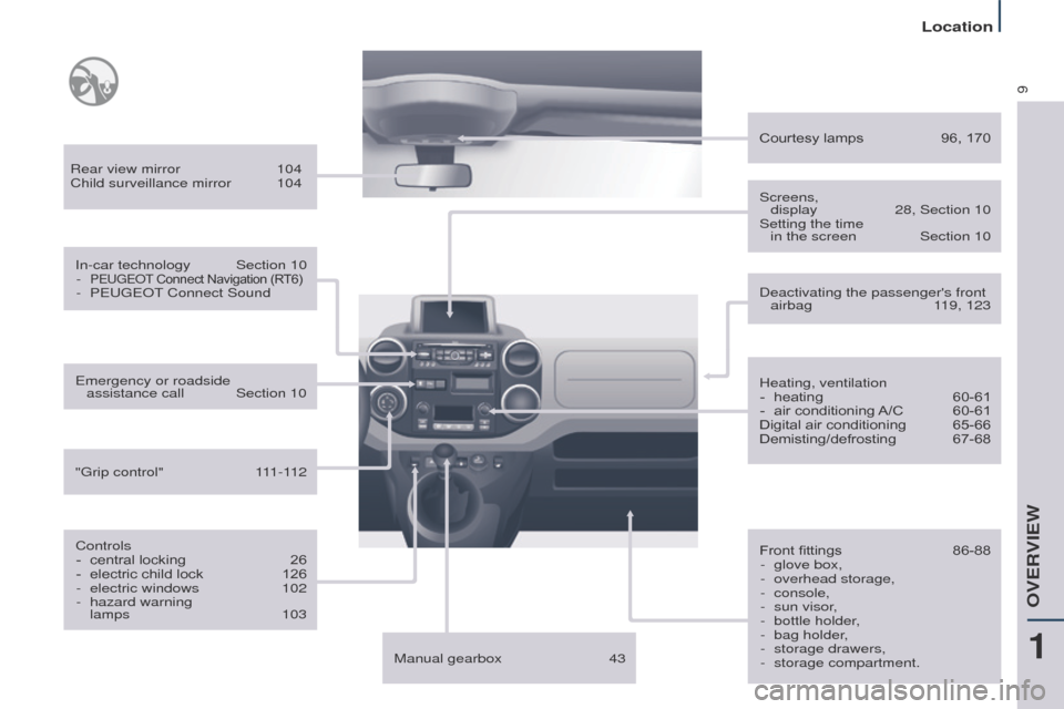
Rear view mirror 104
Child surveillance mirror 104
In-car technology
Section 10
-
PeugeOt Connect Navigation (R T6)- PeugeO t Connect Sound
Controls -
central locking
26
-
electric child lock
126
-
electric windows
102
-
hazard warning
lamps
103
e
mergency or roadside assistance call
Section 10
"
g rip control"
1
11-112 Heating, ventilation
-
heating
60-61
-
air conditioning
A/C
60-61
Digital air conditioning
65-66
Demisting/defrosting
67-68
Courtesy lamps
96, 170
Front fittings
86-88
-
glove box,
-
overhead storage,
-
console,
-
sun visor
,
-
bottle holder
,
-
bag holder
,
-
storage drawers,
-
storage compartment.
Screens,
display
28, Section 10
Setting the time
in the screen
Section 10
Deactivating the passenger's front airbag
1 19, 123
Manual gearbox
43
1
OVeRVIeW
Location
Page 13 of 276
11
Partner_2_VP_en_Chap01_vue-ensemble_ed02-2014
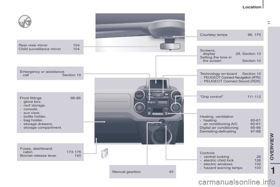
Fuses, dashboard, cabin 173-175
Bonnet release lever
140
Front fititngs
86-88
-
glove box,
-
roof storage,
-
console,
-
sun visor
,
-
bottle holder
,
-
bag holder
,
-
storage drawers,
-
storage compartment.
Rear view mirror
104
Child surveillance mirror
104
e
mergency or assistance
call
Section 10
Manual gearbox
43
technology on-board
Section 10
-
PeugeOt
Connect Navigation (R T6)- PeugeO t Connect Sound (RD5)
Controls -
central locking
26
-
electric child lock
126
-
electric windows
102
-
hazard warning lamps
103
"
g rip control"
1
11-112
Heating, ventilation -
heating
60-61
-
air conditioning
A/C
60-61
Digital air conditioning
65-66
Demisting-defrosting
67-68
Courtesy lamps
96, 170
Screens,
display
28, Section 10
Setting the time in
the screen
Section 10
1
OVeRVIeW
Location
Page 15 of 276
13
Partner_2_VP_en_Chap01_vue-ensemble_ed02-2014
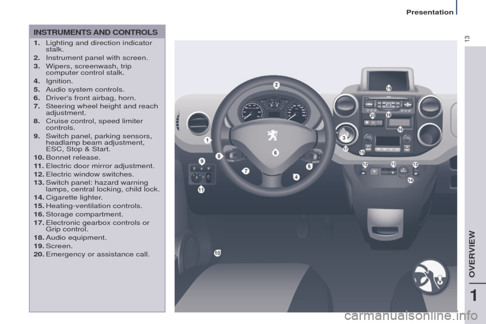
INSTRUMENTS AND CONTROLS
1. Lighting and direction indicator
stalk.
2.
Instrument panel with screen.
3.
Wipers, screenwash, trip
computer control stalk.
4.
Ignition.
5.
Audio system controls.
6.
Driver's front airbag, horn.
7.
Steering wheel height and reach
adjustment.
8.
Cruise control, speed limiter
controls.
9.
Switch panel, parking sensors,
headlamp beam adjustment,
e
SC, Stop & Start.
10.
Bonnet
release.
11 .
e lectric door mirror adjustment.
12.
e lectric window switches.
13.
Switch panel: hazard warning
lamps, central locking, child lock.
14.
Cigarette
lighter.
15.
Heating-ventilation
controls.
16.
Storage
compartment.
17.
e lectronic gearbox controls or
g
rip control.
18.
Audio
equipment.
19.
Screen.
20.
e mergency or assistance call.
1
OVeRVIeW
Presentation
Page 16 of 276
14
Partner_2_VP_en_Chap01_vue-ensemble_ed02-2014
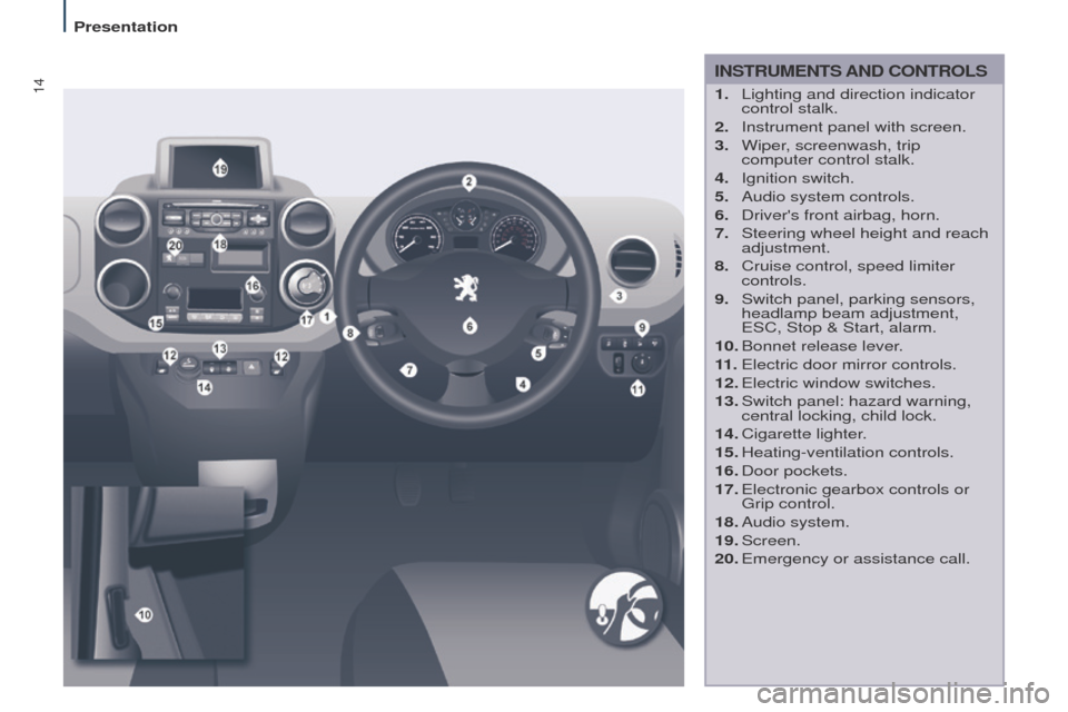
INSTRUMENTS AND CONTROLS
1. Lighting and direction indicator
control stalk.
2.
Instrument panel with screen.
3.
Wiper
, screenwash, trip
computer control stalk.
4.
Ignition switch.
5.
Audio system controls.
6.
Driver's front airbag, horn.
7.
Steering wheel height and reach
adjustment.
8.
Cruise control, speed limiter
controls.
9.
Switch panel, parking sensors,
headlamp beam adjustment,
e
SC, Stop & Start, alarm.
10.
Bonnet release lever
.
11 .
e lectric door mirror controls.
12.
e lectric window switches.
13.
Switch panel: hazard warning,
central locking, child lock.
14.
Cigarette
lighter.
15.
Heating-ventilation
controls.
16.
Door
pockets.
17.
e lectronic gearbox controls or
g
rip control.
18.
Audio
system.
19.
Screen.
20.
e mergency or assistance call.
Presentation
Page 30 of 276
28
Partner_2_VP_en_Chap03_Pret-a-partir_ed02-2014
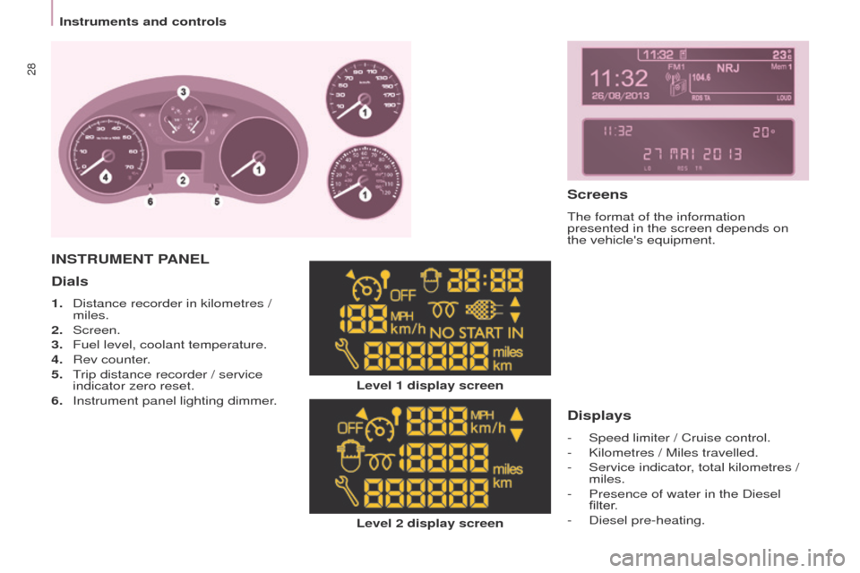
Dials
1. Distance recorder in kilometres /
miles.
2.
Screen.
3.
Fuel level, coolant temperature.
4.
Rev counter
.
5.
t
rip distance recorder / service
indicator zero reset.
6.
Instrument panel lighting dimmer
.
Level 2 display screen
INSTRUMENT PANEL
Level 1 display screen
Displays
- Speed limiter / Cruise control.
-
Kilometres / Miles travelled.
-
Service indicator
, total kilometres /
miles.
-
Presence of water in the Diesel
filter
.
-
Diesel pre-heating.
Screens
the format of the information
presented in the screen depends on
the vehicle's equipment.
Instruments and controls
Page 39 of 276
37
Partner_2_VP_en_Chap03_Pret-a-partir_ed02-2014
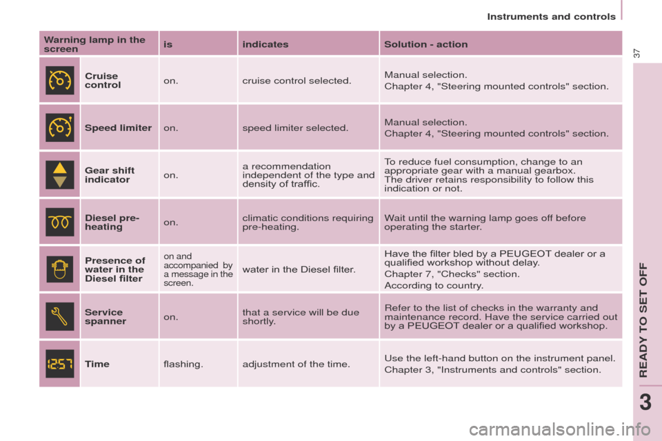
Warning lamp in the
screenis
indicates Solution - action
Cruise
control on.
cruise control selected. Manual selection.
Chapter 4, "Steering mounted controls" section.
Speed limiter on.speed limiter selected. Manual selection.
Chapter 4, "Steering mounted controls" section.
Gear shift
indicator on.a recommendation
independent of the type and
density of traffic.
to reduce fuel consumption, change to an
appropriate gear with a manual gearbox.
t
he driver retains responsibility to follow this
indication or not.
Diesel pre-
heating on.climatic conditions requiring
pre-heating. Wait until the warning lamp goes off before
operating the starter.
Presence of
water in the
Diesel filter
on and
accompanied by
a message in the
screen.
water in the Diesel filter. Have the filter bled by a PEUGEOT dealer or a
qualified workshop without delay.
Chapter 7, "Checks" section.
According to country.
Service
spanner on.that a service will be due
shortly. Refer to the list of checks in the warranty and
maintenance record. Have the service carried out
by a PEUGEOT dealer or a qualified workshop.
Time flashing.adjustment of the time.
u
se the left-hand button on the instrument panel.
Chapter 3, "Instruments and controls" section.
Instruments and controls
ReADY tO Set OFF
3
Page 52 of 276
50
Partner_2_VP_en_Chap03_Pret-a-partir_ed02-2014
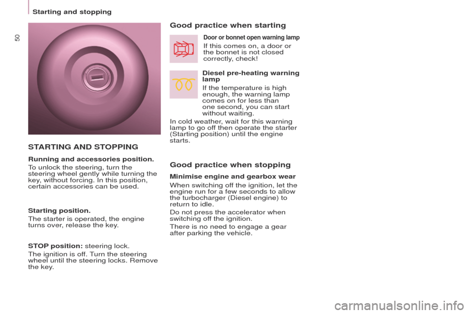
Good practice when stopping Good practice when starting
Diesel pre-heating warning
lamp
If the temperature is high
enough, the warning lamp
comes on for less than
one second, you can start
without waiting.
In cold weather, wait for this warning
lamp to go off then operate the starter
(Starting position) until the engine
starts.
Door or bonnet open warning lamp
If this comes on, a door or
the bonnet is not closed
correctly, check!
Minimise engine and gearbox wear
When switching off the ignition, let the
engine run for a few seconds to allow
the turbocharger (Diesel engine) to
return to idle.
Do not press the accelerator when
switching off the ignition.
t
here is no need to engage a gear
after parking the vehicle.
STARTING AND STOPPING
Running and accessories position.
to unlock the steering, turn the
steering wheel gently while turning the
key
, without forcing. In this position,
certain accessories can be used.
Starting position.
t
he starter is operated, the engine
turns over, release the key.
STOP position: steering lock.
t
he ignition is off.
turn the steering
wheel until the steering locks. Remove
the key
.
Starting and stopping
Page 65 of 276
63
Partner_2_VP_en_Chap04_ergonomie_ed02-2014
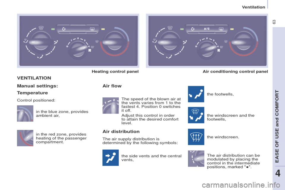
VENTILATION
the side vents and the central
vents,
Air flow
the footwells,
the windscreen and the
footwells,
the windscreen.
t
he air distribution can be
modulated by placing the
control in the intermediate
positions, marked "●".
Manual settings:
Air distribution
the air supply distribution is
determined by the following symbols:
in the red zone, provides
heating of the passenger
compartment. in the blue zone, provides
ambient air
,
t
he speed of the blown air at
the vents varies from 1 to the
fastest 4. Position 0 switches
it off.
Adjust this control in order
to attain the desired comfort
level.
Heating control panel
Air conditioning control panel
Temperature
Control positioned:
Ventilation
eASe OF uSe and COMFORt
4
Page 67 of 276
65
Partner_2_VP_en_Chap04_ergonomie_ed02-2014
Good practice
For maximum cooling or heating of the
passenger compartment, it is possible
to exceed the value 15 by turning until
LO is displayed or the value 27 by
turning until HI is displayed.
On entering the vehicle, the inside
temperature may be much colder (or
warmer) than is comfortable.
t
here is
no advantage in changing the value
displayed in order to quickly reach the
level of comfort required.
t
he system
will use its maximum performance to
reach the comfort value set.
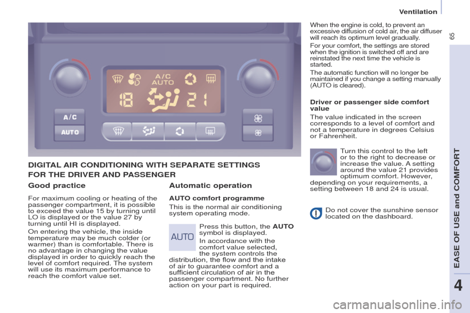
DIGITAL AIR CONDITIONING WITH SEPARATE SETTINGS
Automatic operation
AUTO comfort programme
t
his is the normal air conditioning
system operating mode. Driver or passenger side comfort
value
t
he value indicated in the screen
corresponds to a level of comfort and
not a temperature in degrees Celsius
or Fahrenheit.
turn this control to the left
or to the right to decrease or
increase the value.
A setting
around the value 21 provides
optimum comfort. However,
depending on your requirements, a
setting between 18 and 24 is usual.
Do not cover the sunshine sensor
located on the dashboard.
Press this button, the AUTO
symbol is displayed.
In accordance with the
comfort value selected,
the system controls the
distribution, the flow and the intake
of air to guarantee comfort and a
sufficient circulation of air in the
passenger compartment. No further
action on your part is required.
When the engine is cold, to prevent an
excessive diffusion of cold air, the air diffuser
will reach its optimum level gradually.
For your comfort, the settings are stored
when the ignition is switched off and are
reinstated the next time the vehicle is
started.
t
he automatic function will no longer be
maintained if you change a setting manually
(A
ut
O is cleared).
FOR THE DRIVER AND PASSENGER
Ventilation
eASe OF uSe and COMFORt
4