heating PONTIAC FIERO 1988 Service User Guide
[x] Cancel search | Manufacturer: PONTIAC, Model Year: 1988, Model line: FIERO, Model: PONTIAC FIERO 1988Pages: 1825, PDF Size: 99.44 MB
Page 34 of 1825
HEATING AND VENTILATION 1 A-1 1
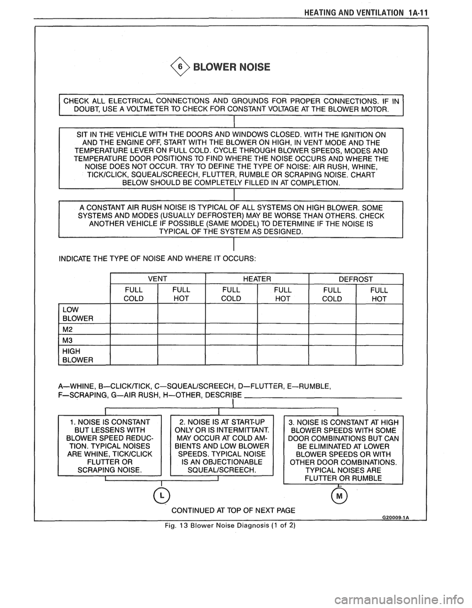
~ @ BLOWER NOISE
SIT IN THE VEHICLE WlTH THE DOORS AND WINDOWS CLOSED. WlTH THE IGNITION ON
AND THE ENGINE OFF, START WITH THE BLOWER ON HIGH, IN VENT MODE AND THE
TEMPERATURE LEVER ON FULL COLD. CYCLE THROUGH BLOWER SPEEDS, MODES AND
TEMPERATURE DOOR POSITIONS TO FIND WHERE THE NOISE OCCURS AND WHERE THE
SYSTEMS AND MODES (USUALLY DEFROSTER) MAY BE WORSE THAN OTHERS. CHECK
ANOTHER VEHICLE IF POSSIBLE (SAME MODEL) TO DETERMINE IF THE NOISE IS
TYPICAL OF THE SYSTEM AS DESIGNED.
INDICATE THE TYPE OF NOISE AND WHERE IT OCCURS:
A-WHINE,
B-CLICKTTICK, C-SQUEALISCREECH, D-FLUTTER, E-RUMBLE,
F-SCRAPING, G--AIR RUSH,
H-OTHER, DESCRIBE
I
BLOWER SPEED REDUC- MAY OCCUR AT COLD AM- DOOR COMBINATIONS BUT CAN
0
CONTINUED AT TOP OF NEXT PAGE G20009-1 A
Fig. 13 Blower Noise Diagnosis (1 of 2)
Page 35 of 1825
1A-12 HEATING AND VENTILATION
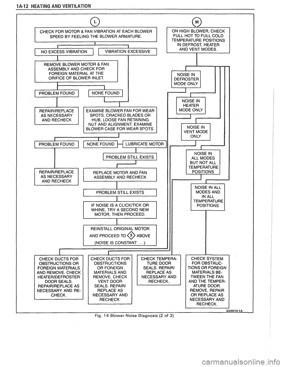
EXAMINE BLOWER FAN FOR WEAR
SPOTS, CRACKED BLADES OR
HUB, LOOSE FAN RETAINING
NUT AND ALIGNMENT. EXAMINE
BLOWER CASE FOR WEAR SPOTS.
REPAIRIREPLACE ASNECESSARY
ANDRECHECK ALL MODES
BUT NOT ALL
TEMPERATURE POSITIONS
AND REMOVE. CHECK MATERIALS AND
HEATERIDEFROSTER REMOVE. CHECK NECESSARY AND
DOOR SEALS. VENT DOOR CHECK SYSTEM
FOR OBSTRUC-
TIONS OR FOREIGN
MATERIALS BE-
TWEEN THE FAN
AND THE TEMPER- ATURE DOOR.
REMOVE, REPAIR
OR REPLACE AS
NECESSARY AND
RECHECK.
Fig.
14 Blower Noise Diagnosis (2 of 2)
Page 36 of 1825
HEATING AND VENTILATION 1.4-1 3
ON-VEHICLE SERVICE
HEATER ELECTRICAL WIRING
The heater wiring diagrams are shown in
Electrical Diagnosis, Section
8A, and should be
referred to for diagnosis of electrical problems in the
heater system.
HEATER CONTROL ASSEMBLY AND BLOWER
SWITCH
Remove or Disconnect
1. Negative battery cable.
2.
Control/radio console trim plate.
3. Three
(3) controller retaining screws and pull
controller out from console.
4. Control cables and electrical connections.
5. Blower switch from controller if either switch or
controller requires replacement. If controller is
being replaced, transfer blower switch to new
controller.
Install or Connect
1. When installing controller, install lower right
screw first to properly align controller in console.
2. Blower switch to controller.
3. Control cables and electrical connections.
4. Three (3) controller retaining screws and
controller to console.
5. Control/radio console trim plate.
6. Negative battery cable.
TEMPERATURE CONTROL, POWER VENT,
HEATER DEFROST CABLE
Remove or Disconnect
1. Hush panel(s) (see Section 8C):
a. Temperature
cable - R.H. hush panel.
b.
Heateddefrost cable - R.H. hush panel.
c. Vent
cable
- L.H. hush panel.
2.
Control/radio console trim plate.
3. Three (3) controller retaining screws and pull
controller out from console.
4. Control cable requiring replacement at control
end.
5. Cable at mode control end (temperature cable:
remove cable link cover at crank location).
Install or Connect
1. When installing controller, install right lower
screw first to align control in console.
2. Cable
at mode control end (temperature cable:
install cable link cover at crank location).
3. Control cable at control end.
4. Three (3) controller retaining screws and
contoller in console.
5. Control/radio console trim plate.
6. Hush panel(s) (see Section 8C).
7. Fully cycle controls to adjust cables and check for
proper operation.
HEATER CORE
Remove or Disconnect
Battery ground cable.
Drain cooling system.
Heater inlet and outlet hoses from heater core.
Right lower hush panel (see Section
8C).
ECM attaching screw and move aside.
Right lower I.P. trim panel (see Section
8C).
Lower right I.P. carrier-to-cowl screw.
Four (4) heater case cover screws. Upper left screw
may be reached with a long socket extension through
the I.P. openings exposed by removal of the lower
right I.P. trim panel. Carefully lift the lower right
corner of the I.P. to align socket extension.
Heater case cover.
Core support plate and baffle screws.
Heater core, support plate and baffle from case.
Install or Connect
1. Heater core, support plate and baffle to case.
2. Core support
plate and baffle screws.
3. Heater case cover.
4. Four (4) heater case cover screws.
5. Lower right I.P. carrier-to-cowl screw.
6. Right lower I.P. trim panel (see Section 8C).
7. ECM.
8. Right lower hush panel (see Section
8C).
9. Heater inlet and outlet hoses to heater core.
10. Refill cooling system and check for leaks.
11. Battery ground cable.
VENT CONTROL CABLE (RAM VENT)
Remove or Disconnect 1
1. Hush panel(s) (see Section 8C). R.H. cable
replacement will require removal of both L.H.
and R.H. hush panels.
2. Two
(2) retaining screws and individual vent
control.
3. Unclip
cable control clamp at vent duct and
disengage formed end of cable from door lever.
1 Install or Connect
1. Cable control clamp at vent duct and install
formed end of cable on door lever.
2, Two (2) retaining screws and individual vent
control.
3. Hush
panel@) (see Section 8C).
4. Cycle
control fully and check for proper
operation.
HEATER CONTROL WIRING I
Remove or Disconnect
1. Negative battery cable.
Page 37 of 1825
1A-14 HEATING AND VENTILATION
2. Control/radio console trim plate and hush
panels.
3. Three (3) screws holding controller in console
and pull controller out far enough to disconnect
electrical connectors.
4. Blower motor and blower resistor electrical
connections.
5. Carefully pull cowl grommet from cowl and pull
wiring harness through cowl hole into engine
compartment.
Install or Connect
1. When reinstalling controller, install lower right
screw first to align controller.
2. Cowl grommet on cowl and wiring harness.
3. Blower motor and blower resistor electrical
connections.
4. Three (3) screws holding controller in console
and connect electrical connectors.
5. Control/radio console trim plate and hush
panels.
6. Negative battery cable.
HEATER/VENTILATION/DEFROSTER DUCTS
See section 8C for removal.
LOWER (FLOOR) HEATER OUTLET
Remove or Disconnect
1. Console (see Section 8C).
2. L.H. and R.H. hush panels. (see Section 8C).
3. Two (2) floor outlet retaining screws.
4. Floor outlet from core case.
Install or Connect
1. Floor outlet to core case.
2. Two (2) floor outlet retaining screws.
3. L.H. and R.H. hush panels.
4. Console.
BLOWER MOTOR
Remove or Disconnect
1. Negative battery cable.
2. Electrical connections at blower motor and
blower resistor.
3. Blower motor cooling tube.
4. Blower motor retaining screws and remove
motor/cage assembly from case.
5. Holding blower motor cage, remove cage
retaining screw and slide cage from motor shaft.
Install or Connect
1. Blower motor cage and retaining screw.
2. Blower
motor retaining screws and
motor/cage
assembly in case.
3. Blower motor cooling tube.
4. Electrical connections at blower motor and
blower resistor.
5. Negative battery cable.
6. Reinstall radio capacitor in proper location, if so
equipped.
Page 39 of 1825
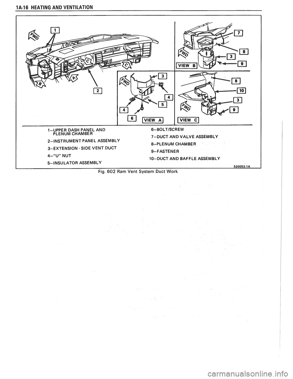
1A-16 HEATING AND VENTILATION
1-UPPER DASH PANEL AND 6- BO LT/SC R E W PLENUM CHAMBER
7-DUCT AND VALVE ASSEMBLY
2-INSTRUMENT PANEL ASSEMBLY
8-PLENUM CHAMBER
3-EXTENSION
- SIDE VENT DUCT
9-FASTENER
4-"U" NUT
10-DUCT AND BAFFLE ASSEMBLY
5-INSU LATOR ASSEMBLY 520052-1A
Fig. 602 Ram Vent System Duct Work
Page 40 of 1825
HEATING AND VENTILATION 1A-17
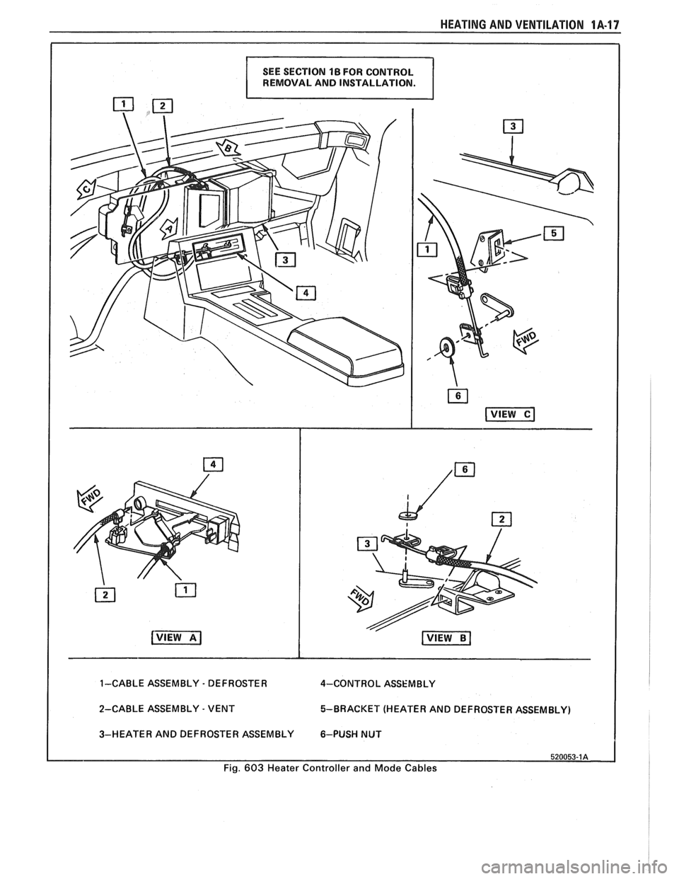
REMOVAL AND INSTALLATION.
1-CABLE ASSEMBLY - DEFROSTER
4-CONTRO L ASSEMBLY
2-CABLE ASSEMBLY
- VENT 5-BRACKET (HEATER
AND DEFROSTER ASSEMBLY)
3-HEATER AND DEFROSTER ASSEMBLY 6-PUSH NUT
520053-1A
Fig. 603 Heater Controller and Mode Cables
Page 41 of 1825
!A-18 HEATING AND VENTILATION
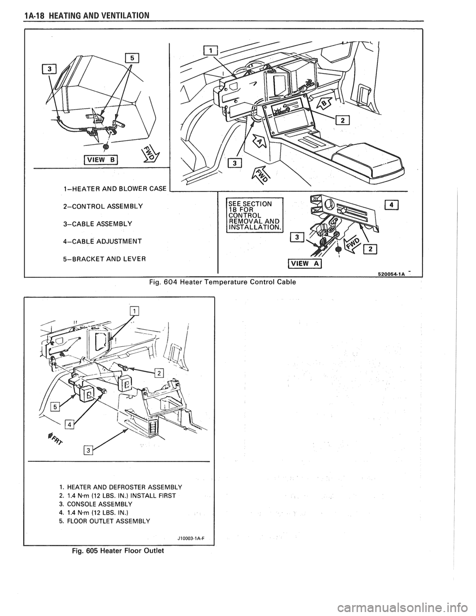
2-CONTROL ASSEMBLY
3-CABLE ASSEMBLY
4-CABLE ADJUSTMENT
Fig. 604 Heater Temperature Control Cable
1. HEATER AND DEFROSTER ASSEMBLY
2. 1.4
N.rn (12 LBS. IN.) INSTALL FIRST
3. CONSOLE ASSEMBLY
4. 1.4 N.rn (12 LBS. IN.)
5. FLOOR OUTLET ASSEMBLY
Fig. 605 Heater Floor Outlet
Page 42 of 1825
HEATING AND VENTILATION 1A-19
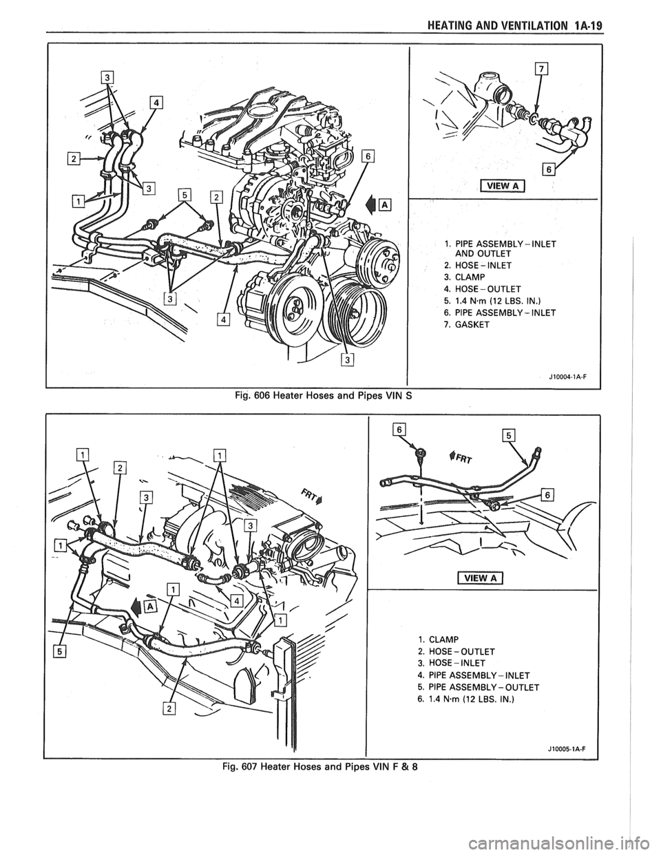
1. PlPE ASSEMBLY - INLET
AND OUTLET
2. HOSE
- INLET
3. CLAMP
4. HOSE -OUTLET
5. 1.4 N.rn (12 LBS. IN.)
6. PlPE ASSEMBLY - INLET
7. GASKET
Fig. 606 Heater Hoses and Pipes VIN S
1. CLAMP
2. HOSE - OUTLET
3. HOSE - INLET
4. PlPE ASSEMBLY - INLET
5. PIPE ASSEMBLY -OUTLET
6. 1.4 N-rn (12 LBS. IN.)
Fig. 607 Heater Hoses and Pipes VIN F & 8
Page 62 of 1825
AIR CONDITIONING 18-19
3. Push the tube into the fitting, bottoming it out.
Tighten
@ Torque nut to 15 Nam (11 lbs. ft.).
4. Dissasemble the joint.
5. Lubricate the
"0" ring with clean 525 viscosity
refrigerant oil.
6. Install the
"0" ring
on the tube. (See figure 17b)
7. Reassemble joint.
Tighten
@ Torque nut to 15 Nem (11 lbs. ft.).
8. Evacuate, charge, and leak test the system.
EXPANSlON "%BE (ORIFICE) SERVlCE
Remove or Disconnect
1. Discharge system.
2. Loosen fitting
at liquid line to evaporator inlet
pipe and remove tube carefully with needle
nosed pliers or Tool
5-26549-C or equivalent.
Install or Connect
1. Install
new orifice tube with shorter screen end
in first.
2. Install
liquid line and torque to proper
specification.
3. Evacuate and charge system.
In the event that difficulty is encountered during
the removal of a restricted or plugged expansion tube
(orifice tube), the following procedure is recom-
mended:
1. Remove
as much of any impacted residue as
possible.
2. Carefully apply heat with heat gun (hair drier,
epoxy drier or equivalent) approximately
114
inch from dimples on inlet pipe. Do not over-
heat pipe.
NOTICE: If the system has a pressure switch
near the orifice tube location, it should be
removed prior to heating the pipe to avoid dam-
age to switch.
3. While applying heat, use orifice removal tool
5-26549-C to grip the orifice tube. Use a turning
motion along with a push-pull motion to loosen
to the impacted orifice tube and remove it.
4. Swab inside of evaporator inlet pipe with R-11.
5, Add
1 oz. of 525 viscosity refrigerant oil to
system.
6. Lubricate new orifice tube and O-ring with 525'
viscosity refrigerant oil and insert into inlet
pipe. Install in proper direction (smaller screen
first).
ACCUMULATOR ASSEMBLY SERVICE
The accumulator assembly for the refrigerant
system has a service replacement which includes two
(2) O-rings (for the inlet and outlet connections). The
desiccant within the shell is NOT serviced separately
- it is part of the sealed accumulator assembly. See
REFRIGERANT OIL DISTRIBUTION for condi-
tions when the accumulator must be removed from the
vehicle to measure the amount of oil present inside the
accumulator.
The accumulator assembly should ONLY be
replaced when:
1. A physical perforation to the accumulator is
found, resulting in a leak.
2. If the system is open to air for an extended
period of time (due to a front-end collision,
removed parts, ect.). The desiccant bag will be
saturated with moisture.
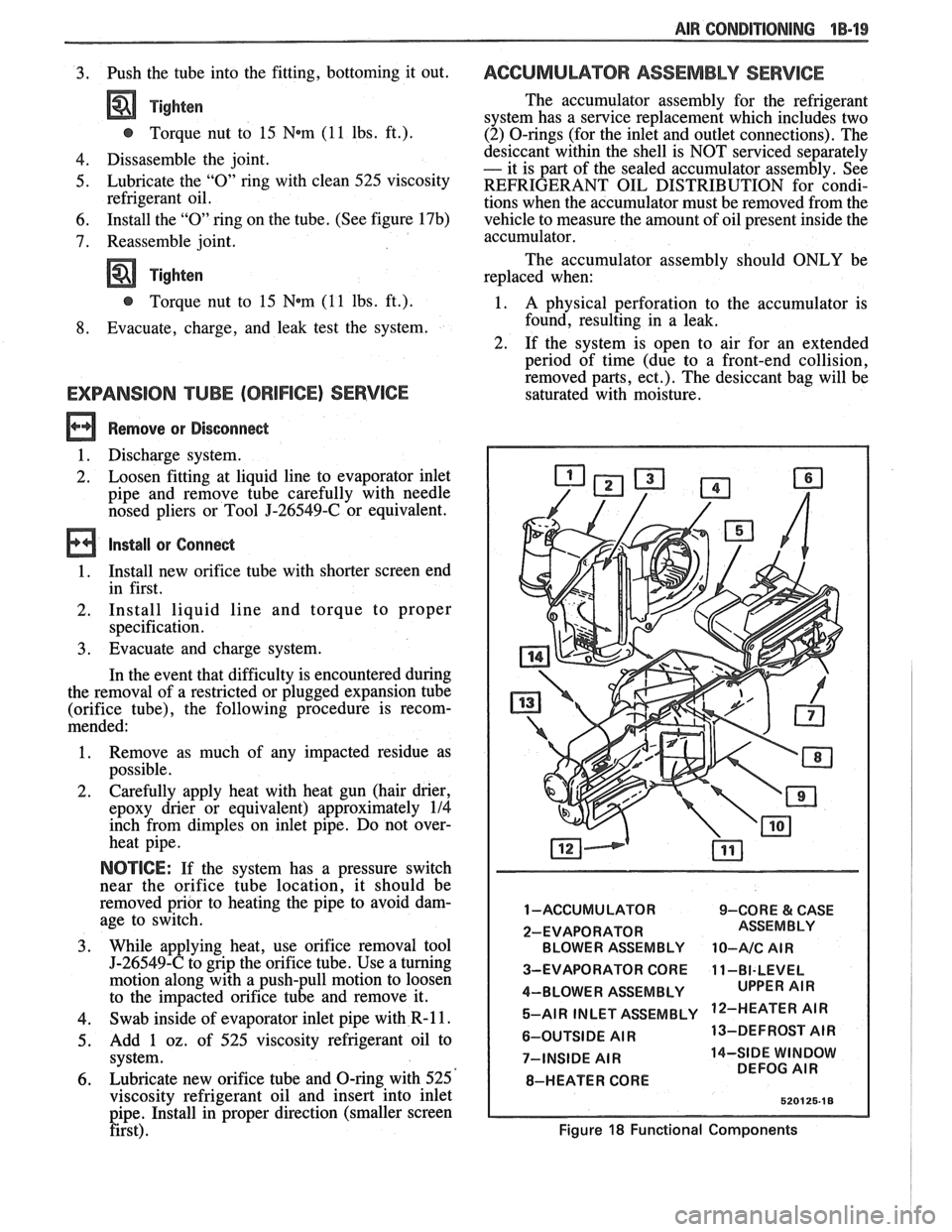
1 -ACCUMULATOR 9-CORE & CASE
2-EVAPORATOR BLOWER ASSEMBLY
10-A/C AIR
3-EVAPORATOR CORE 11-BI-LEVEL
4-BLOWER ASSEMBLY 5-AIR INLET ASSEMBLY
'IR
6-OUTSIDE AIR 13-DEFROST
AIR
7-INSIDE
AIR 14-SIDE WINDOW
DEFOG AIR
8-HEATER CORE
Figure 18 Functional Components
Page 110 of 1825

CHASSIS SHEET METAL 2C-3
3. Allow hood to open, and tighten latch bolts in
new location.
FENDER PANEL
An outer fender panel with a plastic inner panel
is used. Care should be used in handling raw fenders
due to the lack of fender rigidity prior to installation.
Body surfaces at molding areas must be cleaned
thoroughly with suitable organic solvent immediately
prior to installation to ensure adhesion. Do not allow
adhesive surface of molding to come in contact with
wet solvent, dirt, or foreign matter.
NO"FICE: If heat source is used to condition
moldings prior to installation, the source is to
provide
uniform heating, not to exceed 85°F.
Application is to be made in a clean area with
ambient and body surface temperatures of at least
65°F.
The moldings are to be secured with two appli-
cations of a force of 20 pounds for the full length of
each section using a roller or other suitable tool.
Any section of molding removed once in contact
with the body surface must be replaced.
ALUMINUM PANEL REPAIR PROCEDURES
An aluminum hood (inner and outer panel) is
used on some vehicles. An aluminum panel can be
identified by checking it with a magnet, preferably in
the front corners to avoid any possible damage to the
paint. Aluminum will not attract a magnet.
Aluminum panels can be repaired successfully
with only slight changes of materials and techniques
commonly used to refinish steel panels. The necessary
modifications fall into two categories: 1) metal
preparation; and 2) painting.
Metal Preparation
1. Because aluminum is relatively easy to grind,
care must be taken not to use overly coarse abra-
sive discs or excessive grinder speeds (greater
than 2,000 rpm), both of which will cause
excessive heat and unnecessary metal removal.
2. Surface scratches should normally be removed
with 180 or 120 grit paper with scalloped edges.
Hand sanding with 80 grit paper will usually be
sufficient to remove excessive body filler or
heavy scratches, again followed with 180 grit
paper.
NOTICE: Avoid scratching aluminum when
sanding with 80 grit paper by hand.
3. Foam backed pads are recommended for
grinders used on aluminum, rather than the
stiffer rubber pads used for mounting abrasive
discs used on steel. The foam pad helps to
reduce heat build-up and improves blending for
feathering.
4. Localized heat, generated by grinding, can be
minimized by the use of a grease stick, such as
Formax F-160 or equivalent. This does, how-
ever, tend to load up the grinding discs quickly,
which should be periodically cleaned by rotating
them against a brush wetted with solvent.
5. If out-dings or minor convex defects need to be
filed, it is recommended to use a round edge,
double cut, flexible file with 22 teeth per inch
overlaid with 52 teeth per inch (such as
Nicholson
#50-412 or equivalent).
NOTICE: Keep file clean so that chips do not
scratch aluminum.
The use of heat is not recommended, since the
structural characteristics of aluminum are noticeably
affected by heat. A bent or buckled aluminum hood,
which exhibits strain cracks either before or after
straightening, should be replaced.
Both steel and aluminum panels can be metal
prepped and repaired with two-part polyester filler
materials in the same number of operations. The only
differences are that less aggressive type files and abra- sive discs should be used, with care being taken not to
overheat the aluminum.
Painting
Painting procedures for aluminum panels differ
very little from those used on steel panels. Two pre-
cautions should, however, be observed:
1. Alkaline base paint removers are not recom-
mended and should not be used.
2. Aluminum also requires a chemical cleaner such
as
DuPont 2253, Ditzler DX-533, or equivalent
be used on bare metal to remove contaminants
and corrosion. After cleaning, a conversion
coating such as DuPont
226S, Ditzler DX-503
or equivalent should be applied to promote
adhesion.
Beyond these considerations, painting alumi-
num panels should present no increases in difficulty or
changes in procedure and technique.
PAINTING AND REPAIRING NONMETAL
EXTERIOR PARTS 1
FiberglassIABS Plastic Panel Repair ~
A Plastic Solder Repair Kit can be used to repair
cracks, dents, or pits in fiberglass or ABS panels. A
Glass Woven Cloth should be installed on the under
side of a crack in the panel to structurally reinforce the
panel. The following procedure can be used to repair
the panels:
1. With a lacquer removing solvent, remove paint
from damaged area down to the fiberglass or
, ABS material. I
2. Scuff-sand area surrounding damaged area to
provide a good bonding surface.