heating PONTIAC FIERO 1988 Service Owner's Manual
[x] Cancel search | Manufacturer: PONTIAC, Model Year: 1988, Model line: FIERO, Model: PONTIAC FIERO 1988Pages: 1825, PDF Size: 99.44 MB
Page 145 of 1825
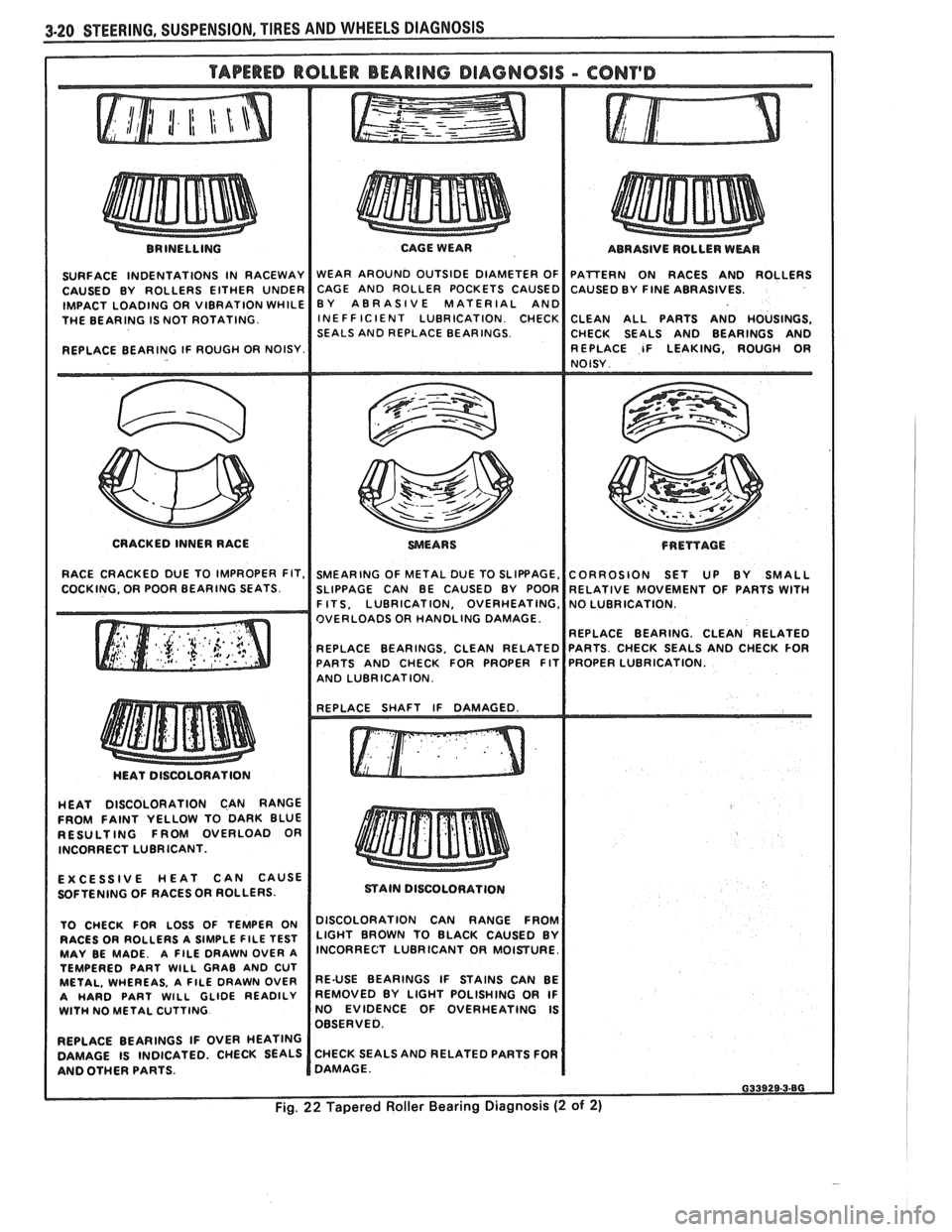
BRINELLING
SURFACE INDENTATIONS IN RACEWAY
CAUSED BY ROLLERS EITHER UNDER
IMPACT LOADING OR VIBRATION WHILE
THE BEARING IS NOT ROTATING.
REPLACE BEARING IF ROUGH OR NOISY. CAGE WEAR
WEAR AROUND OUTSIDE DIAMETER OF
CAGE AND ROLLER POCKETS CAUSED
BY ABRASIVE MATERIAL AND
INE FF IClENT LUBRICATION CHECK
SEALS AND REPLACE BEARINGS. ABRASIVE
ROLLER WEAR
PATTERN ON RACES AND ROLLERS
CAUSED BY
FINE ABRASIVES.
CLEAN ALL PARTS AND HOUSINGS,
CHECK SEALS AND BEARINGS AND
REPLACE IF LEAKING, ROUGH
OR NOISY
CRACKED INNER RACE
WEARS FRETfAGE
RACE CRACKED DUE TO IMPROPER FIT, SMEARING OF METAL DUE TO SLIPBAGE, CORROSION SET UP BY SMALL
COCKING. OR POOR BEARING SEATS. SLIPPAGE CAN BE CAUSED BY POOR RELATIVE MOVEMENT OF PARTS WITH I F ITS. LUBRICATION, OVERHEATING,
OVERLOADS OR HANDLING DAMAGE
REPLACE BEARING. CLEAN RELATED
REPLACE BEARINGS, CLEAN RELATED
PARTS AND CHECK FOR PROPER FIT
I AND LUBRICATION. I I
HEAT DISCOLORATION CAN RANGE
FROM FAINT YELLOW TO DARK BLUE
RESULTING FROM OVERLOAD OR
INCORRECT LUBRICANT.
EXCESSIVE HEAT CAN CAUSE
SOFTENING OF RACES
OR ROLLERS.
TO CHECK FOR LOSS OF TEMPER ON
RACES OR ROLLERS A SIMPLE
FlLE TEST MAY BE MADE. A FILE DRAWN OVER A
TEMPERED PART WlLL GRAB AND CUT
METAL. WHEREAS, A FlLE DRAWN OVER
A HARD PART WlLL GLIDE READILY WlTH NO METAL CUTTING
REPLACE BEARINGS IF OVER HEATING
DAMAGE IS INDICATED. CHECK SEALS
AND OTHER PARTS.
mAIN DISCOLORATION
I DISCOLORATION CAN RANGE FROM
LIGHT BROWN TO BLACK CAUSED BY
INCORRECT LUBRICANT OR MOISTURE.
RE-USE BEARINGS IF STAINS CAN BE
REMOVED BY LIGHT POLISHING OR IF
NO EVIDENCE OF OVERHEATING IS
OBSERVED.
CHECK SEALS AND RELATED PARTS FOR
DAMAGE.
Page 233 of 1825
3E.2 TIRES AND WHEELS
P-METRIC SIZED TIRES
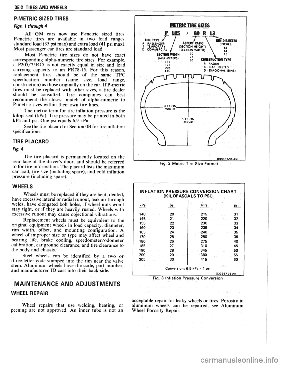
Figs. 1 through 4
All GM cars now use P-metric sized tires.
P-metric tires are available in two load ranges,
standard load
(35 psi max) and extra load (41 psi max).
Most passenger car tires are standard load.
Most P-metric tire sizes do not have exact
corresponding alpha-numeric tire sizes. For example,
a
P205/75R15 is not exactly equal in size and load
carrying capacity to an
FR78-15. For this reason,
replacement tires should be of the same TPC
specification number (same size, load range,
construction) as those originally on the car. If P-metric
tires must be replaced with other sizes, a tire dealer
should be consulted. Tire companies can best
recommend the closest match of alpha-numeric to
P-metric sizes within their own tire lines.
The metric term for tire inflation pressure is the
kilopascal
(kPa). Tire pressure may be printed in both
kPa and psi. One psi equals 6.9 kPa.
See the tire placard or Section OB for tire inflation
specifications.
TlRE PLACARD
Fig. 4
The tire placard is permanently located on the
rear
face of the driver's door, and should be referred
to for tire information. The placard lists the maximum
car load, tire size (including spare), and cold inflation
pressure (including spare).
WHEELS
Wheels must be replaced if they are bent, dented,
have excessive lateral or radial
runout, leak air through
welds, have elongated bolt holes, if wheel nuts won't
stay tight, or if they are heavily rusted. Wheels with
excessive
runout may cause objectional vibrations.
Replacement wheels must be equivalent to the
original equipment wheels in load capacity, diameter,
rim width, offset, and mounting configuration.
A
wheel of improper size or type may affect wheel and
bearing life, brake cooling,
speedometer/odometer
calibration, car ground clearance, and tire clearance to
the body and chassis.
Steel wheels can be identified by a two or
three-letter code stamped into the rim near the valve
stem. Aluminum wheels have the code, part number,
and manufacturer
ID cast into their back side.
MAINTENANCE AND ADJUSTMENTS
WHEEL REPAIR
Wheel repairs that use welding, heating, or
peening are not approved. An inner tube is not an
Fig. 2 Metric Tire Size Format
INFLATION PRESSURE CONVERSION CHART (KI LOPASCALS TO PSI)
Fig. 3 Inflation Pressure Conversion
acceptable repair for leaky wheels or tires. Porosity in
aluminum wheels can be repaired, see Aluminum
Wheel Porosity Repair.
Page 245 of 1825
4A-4 PROPELLER SHAFT
PROPELLER SHAFT BALANCING
Hose Clamp Method
Figures 4A- 1 1 thru 4A-13
1. Place the vehicle on a twin post hoist so that the
rear of the vehicle is supported on the rear axle
housing and the rear wheels are free to rotate.
Remove both rear wheel assemblies and reinstall
wheel lug nuts with flat sides next to
drums/discs.
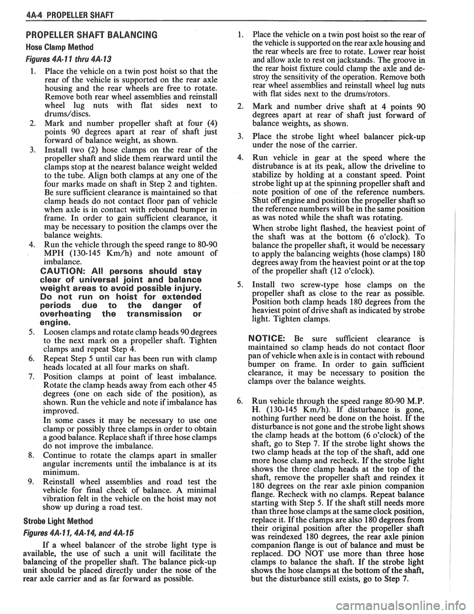
2. Mark and number propeller shaft at four (4)
points 90 degrees apart at rear of shaft just
forward of balance weight, as shown.
3. Install two (2) hose clamps on the rear of the
propeller shaft and slide them rearward until the
clamps stop at the nearest balance weight welded
to the tube. Align both clamps at any one of the
four marks made on shaft in Step 2 and tighten.
Be sure sufficient clearance is maintained so that
clamp heads do not contact floor pan of vehicle
when axle is in contact with rebound bumper in
frame. In order to gain sufficient clearance, it
may be necessary to position the clamps over the
balance weights.
4. Run the vehicle through the speed range to 80-90
MPH (130-145
Km/h) and note amount of
imbalance.
CAUTION: All persons should stay
clear of universal joint and balance
weight areas to avoid possible injury.
Do not run on hoist for extended
periods due to the danger of
overheating the transmission or
engine.
5. Loosen clamps and rotate clamp heads 90 degrees
to the next mark on a propeller shaft. Tighten
clamps and repeat Step 4.
6. Repeat Step 5 until car has been run with clamp
heads located at all four marks on shaft.
7. Position clamps at point of least imbalance.
Rotate the clamp heads away from each other 45
degrees (one on each side of the position), as
shown. Run the vehicle and note if imbalance has
improved.
In some cases it may be necessary to use one
clamp or possibly three clamps in order to obtain
a good balance. Replace shaft if three hose clamps
do not improve the imbalance.
8. Continue to rotate the clamps apart in smaller
angular increments until the imbalance is at its
minimum.
9. Reinstall wheel assemblies and road test the
vehicle for final check of balance. A minimal
vibration felt in the vehicle on the hoist may not
show up during a road test.
Strobe Light Method
Figures 461- 1 1, $A- 14, and 4A- 15
If a wheel balancer of the strobe light type is
available, the use of such a unit will facilitate the
balancing of the propeller shaft. The balance pick-up
unit should be placed directly under the nose of the
rear axle carrier and as far forward as possible. 1.
Place
the vehicle on a twin post hoist so the rear of
the vehicle is supported on the rear axle housing and
the rear wheels are free to rotate. Lower rear hoist
and allow axle to rest on jackstands. The groove in
the rear hoist fixture could clamp the axle and de-
stroy the sensitivity of the operation. Remove both
rear wheel assemblies and reinstall wheel lug nuts
with flat sides next to the
drums/rotors.
2.
Mark and number drive shaft at 4 points 90
degrees apart at rear of shaft just forward of
balance weights, as shown.
3. Place the strobe light wheel balancer pick-up
under the nose of the carrier.
4. Run vehicle in gear at the speed where the
distrubance is at its peak, allow the driveline to
stabilize by holding at a constant speed. Point
strobe light up at the spinning propeller shaft and
note position of one of the reference numbers.
Shut off engine and position the propeller shaft so
the reference numbers will be in the same position
as was noted while the shaft was rotating.
When strobe light flashed, the heaviest point of
the shaft was at the bottom (6 o'clock). To
balance the propeller shaft, it would be necessary
to apply the balancing weights (hose clamps) 180
degrees away from the heaviest point or at the top
of the propeller shaft (12 o'clock).
5. Install two screw-type hose clamps on the
propeller shaft as close to the rear as possible.
Position both clamp heads 180 degrees from the
heaviest point of drive shaft as indicated by strobe
light. Tighten clamps.
NOTICE: Be sure sufficient clearance is
maintained so clamp heads do not contact floor
pan of vehicle when axle is in contact with rebound
bumper on frame. In order to gain. sufficient
clearance, it may be necessary to position the
clamps over the balance weights.
6. Run vehicle through the speed range 80-90
M.P.
H. (130-145 Km/h). If disturbance is gone,
nothing further need be done on the hoist. If the
disturbance is not gone and the strobe light shows
the clamp heads at the bottom (6 o'clock) of the
shaft, go to Step
7. If the strobe light shows the
two clamp heads at the top of the shaft, add one
more hose clamp and recheck. If the strobe light
shows the three clamp heads at the top of the
shaft, remove the propeller shaft and
reindex it
180 degrees on the rear axle pinion companion
flange. Recheck with no clamps. Repeat balance
starting with Step 5. If the shaft still needs more
than three hose clamps at the same clock position,
replace it. If the clamps are also 180 degrees from
their original position after the propeller shaft
was reindexed 180 degrees, the rear axle pinion
companion flange is out of balance and must be
replaced. DO NOT use more than three hose
clamps to balance the shaft. If the strobe light
shows the hose clamps at the bottom of the shaft,
but the disturbance still exists, go to Step
7.
Page 259 of 1825
4B1-6 REAR AXLE
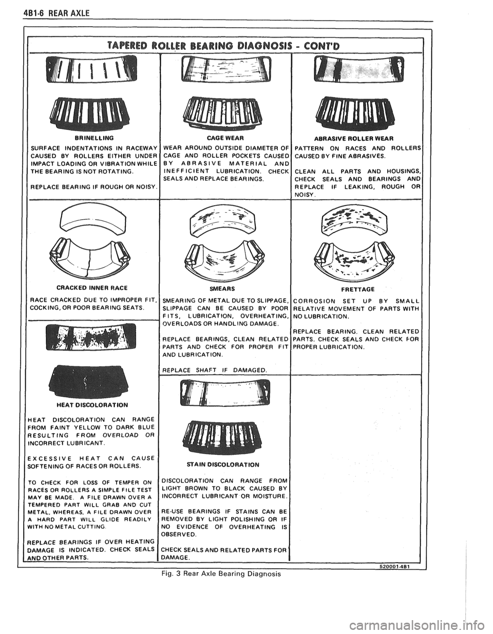
THE BEARING IS NOT ROTATING.
SEALS AND REPLACE BEARINGS. CHECK SEALS AND BEARINGS AND
CRACKED INNER RACE
F R ETTAGE
OVERLOADS OR HANDLING DAMAGE.
AND LUBRICATION.
HEAT DISCOLORATION CAN RANGE
FROM FAINT YELLOW TO DARK BLUE
RESULTING FROM OVERLOAD OR
INCORRECT LUBRICANT.
EXCESSIVE HEAT CAN CAUSE
SOFTENING OF RACES OR ROLLERS.
STAIN DISCOLORATION
TEMPERED PART
WILL GRAB AND CUT
WITH NO METAL CUTTING. NO EVIDENCE OF OVERHEATING IS
Fig. 3 Rear Axle Bearing Diagnosis
Page 278 of 1825
REAR AXLE 48-5
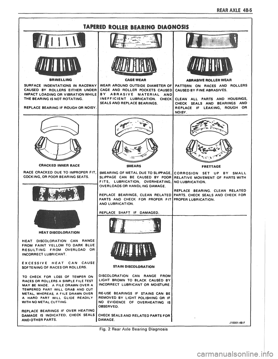
BRINELLIM
SURFACE INDENTATIONS IN RACEWAY
CAUSED BY ROLLERS EITHER UNDER
IMPACT LOADING OR VIBRATION WHILE
THE BEARING IS NOT ROTATING.
REPLACE BEARING IF ROUGH OR NOISY.
I
CRACKED INNER RACE
RACE CRACKED DUE TO IMPROPER FIT,
COCKING, OR POOR BEARING SEATS.
mOE WEAR
WEAR AROUND OUTSIDE DIAMETER OF
CAGE AND ROLLER POCKETS CAUSEC
BY ABRASIVE MATERIAL
AN0 INEFFICIENT LUBRICATION. CHECK
SEALS AND REPLACE BEARINGS.
SMEARING OF METAL DUE TO SLIPPAGE,
SLIPPAGE CAN BE CAUSED BY POOR
F ITS, LUBRICATION, OVERHEATING,
OVERLOADS OR HANDLING DAMAGE.
REPLACE BEARINGS. CLEAN RELATED
PARTS AND CHECK FOR PROPER FIT
AND LUBRICATION. ABRASIVE
ROLLER
WUR
PAmERN ON RACES AND ROLLERS
CAUSED BY FINE ABRASIVES.
CLEAN ALL PARTS AND HOUSINGS,
CHECK SEALS AND BEARINGS AND
REPLACE IF LEAKING, ROUGH
OR NOISY.
FRETTACE
CORROSION SET UP BY SMALL
RELATIVE MOVEMENT OF PARTS WlTH
NO LUBRICATION.
REPLACE BEARING. CLEAN RELATED
PARTS. CHECK SEALS AND CHECK FOR
PROPER LUBRICATION.
HEAT DISCOLORATION CAN RANGE
FROM FAINT YELLOW TO DARK BLUE
RESULTING FROM OVERLOAD OR
INCORRECT LUBRICANT.
EXCESSIVE
HEAT CAN CAUSE
SOFTENING OF RACES OR ROLLERS.
TO CHECK FOR LOSS OF TEMPER ON
DISCOLORATION CAN RANGE FFmM RACES OR ROLLERS A SIMPLE FILE TEST LIGHT BROWN TO BLACK CAUSED BY MAY BE MADE. A FILE DRAWN OVER A lNCORRECT LUBRICANT OR MOISTURE.
TEMPERED PART
WlLL GRAB AND CUT METAL, WHEREAS. A FILE DRAWN OVER RE-USE BEARINGS IF STAINS CAN BE
A HARD PART WILL GLIDE READILY REMOVED BY LIGHT POLISHING OR IF WITH NO METAL CUTTING NO EVIDENCE OF OVERHEATING IS
OBSERVED.
REPLACE BEARINGS IF OVER
HEATING
DAMAGE IS INDICATED. CHECK SEALS CHECK SEALS AND RELATED PARTS FOR
AND OTHER PARTS. DAMAGE.
J10001-40-F
Fig. 2 Rear Axle Bearing Diagnosis
Page 412 of 1825
ENGINE COOLING 6B-1
SECTION 6B
NE COOL
General Description ................................ 6B- 1 Off-Vehicle Leak Testing ............................... 6B-9
Radiator
...................................................... 6B- 1 Repairable Leaks ........................ ... .......... 6B- 10
Radiator Cap
......................... .. ............... 6B- 1 Repair Methods ................................................ 6B- 10
Recovery Bottle ......................................... 6B-2 Cooling Fin Removal ................................ 6B- 10 - ............................................. Fans ............................................................... 6B-2 Tube Blocking 6B- 1 1 ............ Header Repair ....................... .... 6B- 1 1 Temperature Switch ..................................... 6B-2 General Core Repair 6B- 1 1 ....................................
........................... Coolant Temperature Fan Switch ................ 6B-2 Tank
Gasket ~eik Repair 6B- 12
................... Thermostat .. 6B-3 Oil
Cooler Gasket Replacement
6B- 13 ............... ................................
...........................................................
Coolant Recovery System 6B-3 Recore 6B- 14 ............................. Special Tools ..................................................... 6B- 14 Diagnosis ..................................................... 6B-3
.............................. ..................................... Service Procedures 6B-3 On-Vehicle Service 6B-14
Cooling System Care
............................... 6B-3 Thermostat ....................................... 6B-14
Draining and Refilling the Cooling Electric Cooling Fan ............................. 6B-15
System
................................................... 6B-7 Water Pump .................... .... ......... 6B-15
Drive Belt
...................... .. .......................... 6B-7 Coolant Recovery Bottle ........................ 6B-16
.......................................... Aluminum Radiator Service .................... 6B-8 Radiator 6B-17
Diagnosis .................................................... 6B-8
Leak Testing
.............................................. 6B-8
On-Vehicle Pressure Testing
...................... .... 6B-9
GENERAL DESCRIPnIBN
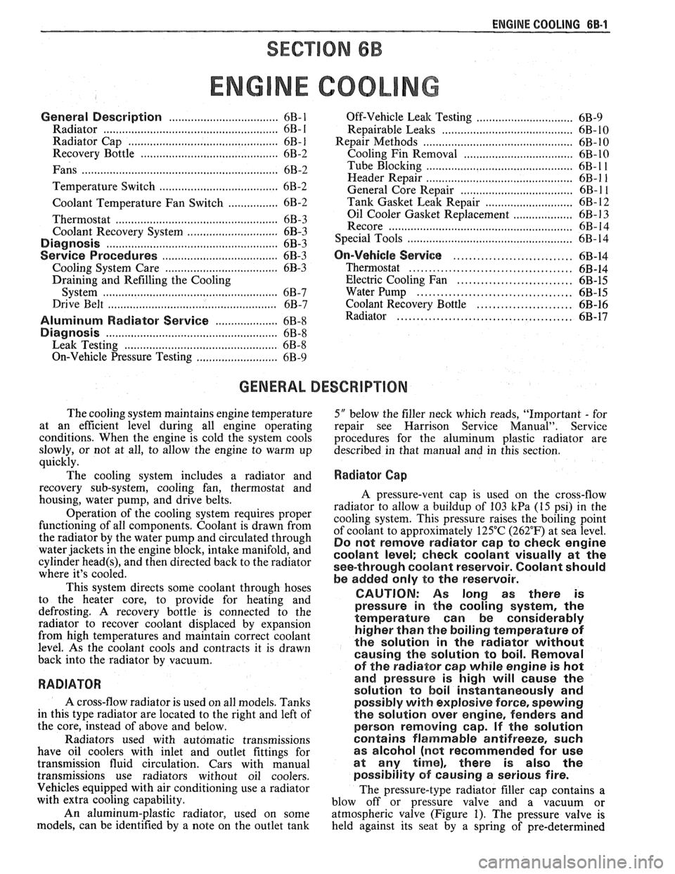
The cooling system maintains engine temperature
5" below the filler neck which reads, "Important - for
at an efficient level during all engine operating repair see Harrison Service Manual". Service
conditions. When the engine is cold the system cools procedures for the aluminum plastic radiator are
slowly, or not at all, to allow the engine to warm up described in that manual and in this section.
quickly.
The cooling system includes a radiator and
Radiator Cap
recovery sub-system, cooling fan, thermostat and
housing, water pump, and drive belts.
Operation of the cooling system requires proper
functioning of all components. Coolant is drawn from
the radiator by the water pump and circulated through
water jackets in the engine block, intake manifold, and
cylinder
head(s), and then directed back to the radiator
where it's cooled.
This system directs some coolant through hoses
to the heater core, to provide for heating and
defrosting. A recovery bottle is connected to the
radiator to recover coolant displaced by expansion
from high temperatures and maintain correct coolant
level. As the coolant cools and contracts it is drawn
back into the radiator by vacuum.
RADIATOR
A cross-flow radiator is used on all models. Tanks
in this type radiator are located to the right and left of
the core, instead of above and below.
Radiators used with automatic transmissions
have oil coolers with inlet and outlet fittings for
transmission fluid circulation. Cars with manual
transmissions use radiators without oil coolers.
Vehicles equipped with air conditioning use a radiator
with extra cooling capability.
An aluminum-plastic radiator, used on some
models, can be identified by a note on the outlet tank A pressure-vent
cap is used on the cross-flow
radiator to allow a buildup of
103 kPa (15 psi) in the
cooling system. This pressure raises the boiling point
of coolant to approximately 125°C (262°F) at sea level.
Do not remove radiator cap to check engine
coolant level; check coolant visually at the
see-through coolant reservoir. Coolant should
be added only
to the reservoir.
CAUTION: As long as there
is
pressure in the cooling system, the
temperature can be considerably
higher than the boiling temperature
of
the solution in the radiator without
causing the solution to boil. Removal
of the radiator cap while engine is hot
and pressure is high will cause
the
solution to boil instantaneously and
possibly with explosive
force, spewing
the solution over engine, fenders and
person removing cap. If the solution
contains flammable antifreeze, such
as alcohol (not recommended for use
at any time), there is also the
possibility
of causing a serious fire.
The pressure-type radiator filler cap contains a
blow off or pressure valve and a vacuum or
atmospheric valve (Figure
1). The pressure valve is
held against its seat by a spring of pre-determined
Page 415 of 1825
BB.4 ENGINE COOLING
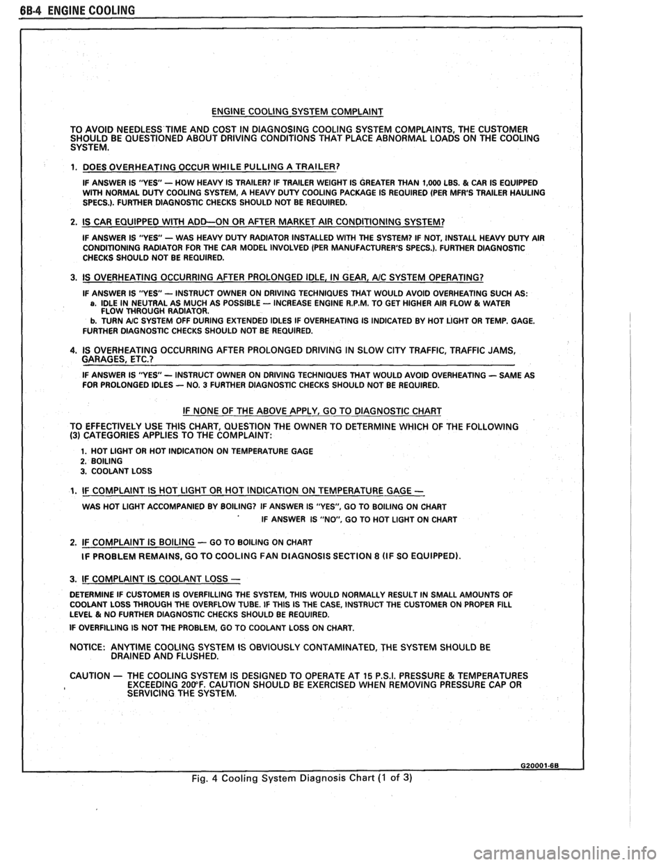
ENGINE COOLING SYSTEM COMPLAINT
TO AVOID NEEDLESS
TIME AND COST IN DIAGNOSING COOLING SYSTEM COMPLAINTS, THE CUSTOMER
SHOULD BE QUESTIONED ABOUT DRIVING CONDITIONS THAT PLACE ABNORMAL LOADS ON THE COOLING
SYSTEM.
1. DOES OVERHEATING OCCUR WHILE PULLING A TRAILER?
IF ANSWER IS "YES'- HOW HEAVY IS TRAILER? IF TRAILER WEIGHT IS GREATER THAN 1,000 LBS. & CAR IS EQUIPPED
WITH NORMAL DUTY COOLING SYSTEM, A HEAVY DUTY COOLING PACKAGE IS REQUIRED (PER MFR'S TRAILER HAULING
SPECS.). FURTHER DIAGNOSTIC CHECKS SHOULD NOT BE REQUIRED.
2. IS CAR EQUIPPED WlTH ADD-ON OR AFTER MARKET AIR CONDITIONING SYSTEM?
IF ANSWER IS "YES"- WAS HEAVY DUTY RADIATOR INSTALLED WITH THE SYSTEM? IF NOT, INSTALL HEAVY DUTY AIR
CONDITIONING RADIATOR FOR THE CAR MODEL INVOLVED (PER MANUFACTURER'S SPECS.). FURTHER DlAGNOSTlC
CHECKS SHOULD NOT BE REQUIRED.
3. IS OVERHEATING OCCURRING AFTER PROLONGED IDLE, IN GEAR, AIC SYSTEM OPERATING?
IF ANSWER IS "YES - INSTRUCT OWNER ON DRIVING TECHNIQUES THAT WOULD AVOID OVERHEATING SUCH AS: a, IDLE IN NEUTRAL AS MUCH AS POSSIBLE - INCREASE ENGINE R.P.M. TO GET HIGHER AIR FLOW & WATER
FLOW THROUGH RADIATOR.
b. TURN A/C SYSTEM OFF DURING EXTENDED IDLES IF OVERHEATING IS INDICATED BY HOT LIGHT OR TEMP. GAGE.
FURTHER DIAGNOSTIC CHECKS SHOULD NOT BE REQUIRED.
4. IS OVERHEATING OCCURRING AFTER PROLONGED DRIVING IN SLOW CITY TRAFFIC, TRAFFIC JAMS,
GARAGES, ETC.?
IF ANSWER IS "YES - INSTRUCT OWNER ON DRIVING TECHNIQUES THAT WOULD AVOID OVERHEATING - SAME AS
FOR PROLONGED IDLES - NO. 3 FURTHER DIAGNOSTIC CHECKS SHOULD NOT BE REQUIRED.
IF NONE OF THE ABOVE APPLY, GO TO DIAGNOSTIC CHART
TO EFFECTIVELY USE THlS CHART, QUESTION THE OWNER TO DETERMINE WHICH OF THE FOLLOWING
(3) CATEGORIES APPLIES TO THE COMPLAINT:
1. HOT LlGHT OR HOT INDICATION ON TEMPERATURE GAGE 2. BOILING 3. COOLANT LOSS
1. IF COMPLAINT IS HOT LlGHT OR HOT INDICATION ON TEMPERATURE GAGE -
WAS HOT LlGHT ACCOMPANIED BY BOILING? IF ANSWER IS "YES", GO TO BOILING ON CHART
IF ANSWER IS "NO, GO TO HOT LlGHT ON CHART
2. IF COMPLAINT IS BOILING - GO TO BOILING ON CHART
IF PROBLEM REMAINS, GO TO COOLING
FAN DIAGNOSIS SECTION 8 (IF SO EQUIPPED).
I 3. IF COMPLAINT IS COOLANT LOSS -
DETERMINE IF CUSTOMER IS OVERFILLING THE SYSTEM, THlS WOULD NORMALLY RESULT IN SMALL AMOUNTS OF
I COOLANT LOSS THROUGH THE OVERFLOW TUBE. IF THlS IS THE CASE, INSTRUCT THE CUSTOMER ON PROPER FILL LEVEL & NO FURTHER DIAGNOSTIC CHECKS SHOULD BE REQUIRED.
I IF OVERFILLING IS NOT THE PROBLEM, GO TO COOLANT LOSS ON CHART.
NOTICE:
ANYTIME COOLING SYSTEM IS OBVIOUSLY CONTAMINATED, THE SYSTEM SHOULD BE
DRAINED AND FLUSHED.
1 CAUTION - THE COOLING SYSTEM IS DESIGNED TO OPERATE AT 15 P.S.I. PRESSURE & TEMPERATURES
EXCEEDING 200°F. CAUTION SHOULD BE EXERCISED WHEN REMOVING PRESSURE CAP OR
I SERVICING THE SYSTEM.
Fig. 4 Cooling System Diagnosis Chart (I of 3)
Page 417 of 1825
6B-8 ENGINE COOLING
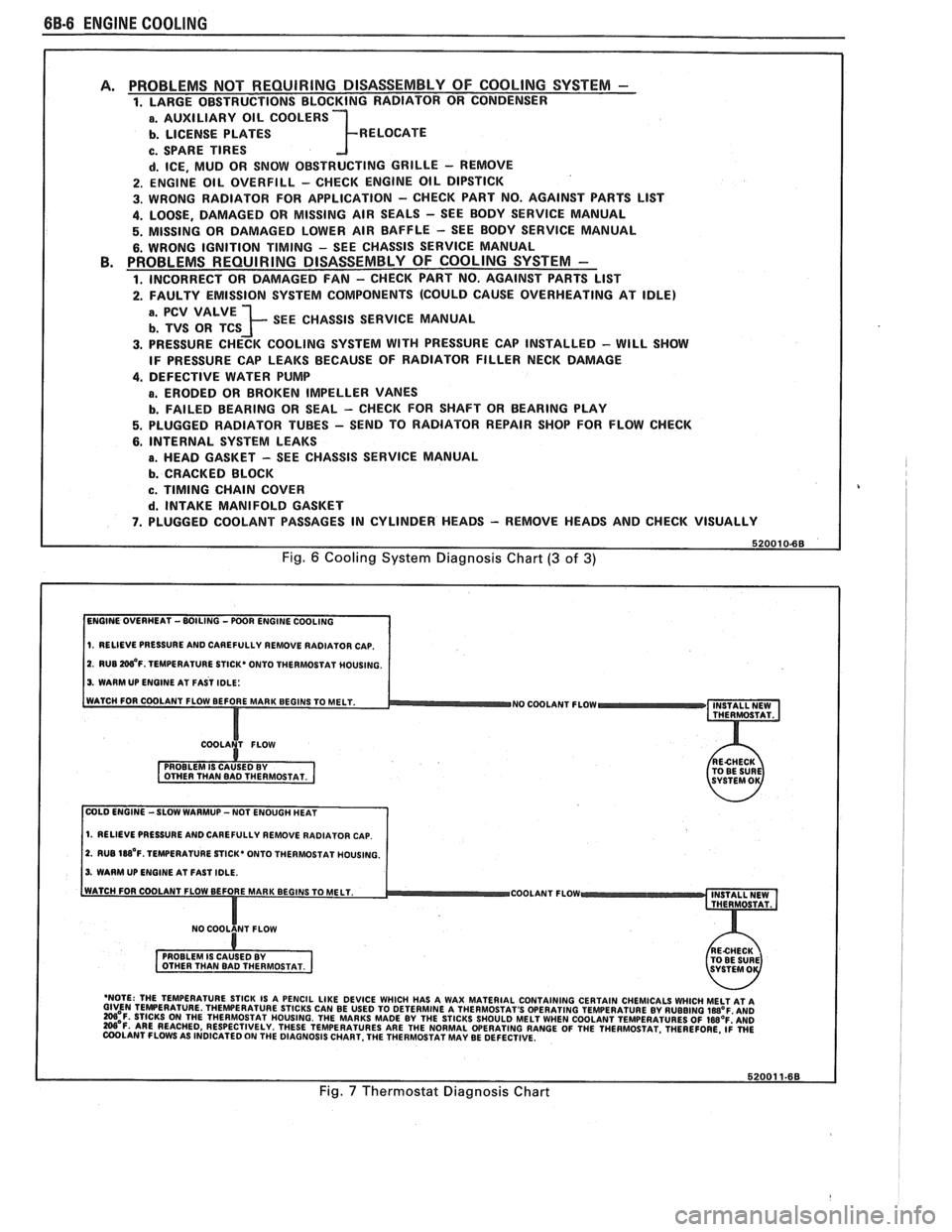
PROBLEMS NOT REQUIRING DISASSEMBLY OF COOLING SYSTEM - 1. LARGE OBSTRUCTIONS BLOCKING RADIATOR OR CONDENSER
a. AUXILIARY OIL COOLERS
b. LICENSE PLATES R ELOCATE
c. SPARE TIRES
d. ICE, MUD OR SNOW OBSTRUCTING GRILLE - REMOVE
2. ENGINE OIL OVERFILL - CHECK ENGINE OIL DIPSTICK
3. WRONG RADIATOR FOR
APPLICATION - CHECK PART NO. AGAINST PARTS LlST
4. LOOSE, DAMAGED OR MISSING AIR SEALS - SEE BODY SERVICE MANUAL
5. MISSING OR DAMAGED LOWER AIR BAFFLE - SEE BODY SERVICE MANUAL
6. WRONG IGNITION TIMING - SEE CHASSIS SERVICE MANUAL PROBLEMS REQUIRING DISASSEMBLY OF COOLING SYSTEM -
1. INCORRECT OR DAMAGED FAN - CHECK PART NO. AGAINST PARTS LlST
2. FAULTY EMISSION SYSTEM COMPONENTS (COULD CAUSE OVERHEATING AT IDLE)
; SEE CHASSIS SERVICE MANUAL
3. PRESSURE CHECK COOLING SYSTEM WITH PRESSURE CAP INSTALLED - WILL SHOW
IF PRESSURE CAP LEAKS BECAUSE OF RADIATOR FILLER NECK DAMAGE
4. DEFECTIVE WATER PUMP
a. ERODED OR BROKEN IMPELLER VANES
b. FAILED BEARING OR SEAL - CHECK FOR SHAFT OR BEARING PLAY
5. PLUGGED RADIATOR TUBES - SEND TO RADIATOR REPAIR SHOP FOR FLOW CHECK
6. INTERNAL SYSTEM LEAKS
B. HEAD GASKET - SEE CHASSIS SERVICE MANUAL
b. CRACKED BLOCK
c. TIMING CHAIN COVER
d. INTAKE MANIFOLD GASKET
7. PLUGGED COOLANT PASSAGES IN CYLINDER HEADS - REMOVE HEADS AND CHECK VISUALLY
Fig. 6 Cooling System Diagnosis Chart (3 of 3)
1. RELIEVE PRESSURE AND CAREFULLY REMOVE RADIATOR CAP.
2. RUB W'F. TEMPERATURE STICK* ONTO THERMOSTAT MOUSING.
3. WARM UP ENGINE AT FAST IDLE:
WATCH FOR COOLANT FLOW BEFORE MAR
NO COOLANT FLOW INSTALL NEW
THERMOSTAT.
COLD ENGINE -SLOW WARMUP -NOT ENOUGH HEAT
1. RELIEVE PRESSURE AND CAREFULLY REMOVE RADIATOR CAP.
2. RUB 188'~. TEMPERATURE STICK' ONTO THERMOSTAT HOUSING.
3. WARM UP ENGINE AT FAST IDLE.
COOLANT FLOW
- 'NOTE: THE TEMPERATURE STICK IS A PENCIL LIKE DEVICE WHICH HAS A WAX MATERIAL CONTAINING CERTAIN CHEMICALS WHICH MELT AT A GIVEN TEMPERATURE THEWERATURE STICKS CAN BE USED TO DETERMINE A THERMOSTAT'S OPERATING TEMPERATURE BY RUBBING laB°F AN0 =OF. STICKS ON THE THERMOSTAT HOUSING. THE MARKS MADE BY THE STICKS SHOULD MELT WHEN COOLANT TEMPERATURES OF IWOF'AND W'F. ARE REACHED, RESPECTIVELY. THESE TEMPERATURES ARE THE NORMAL WERATING RANGE OF THE THERMOSTAT. THEREFORE, ~i WE COOLANT FLOWS AS INDICATED ON THE DIAGNOSIS CHART. THE THERMOSTAT MAY BE DEFECTIVE.
Fig. 7 Thermostat Diagnosis Chart
Page 423 of 1825
88-12 ENGINE COOLING
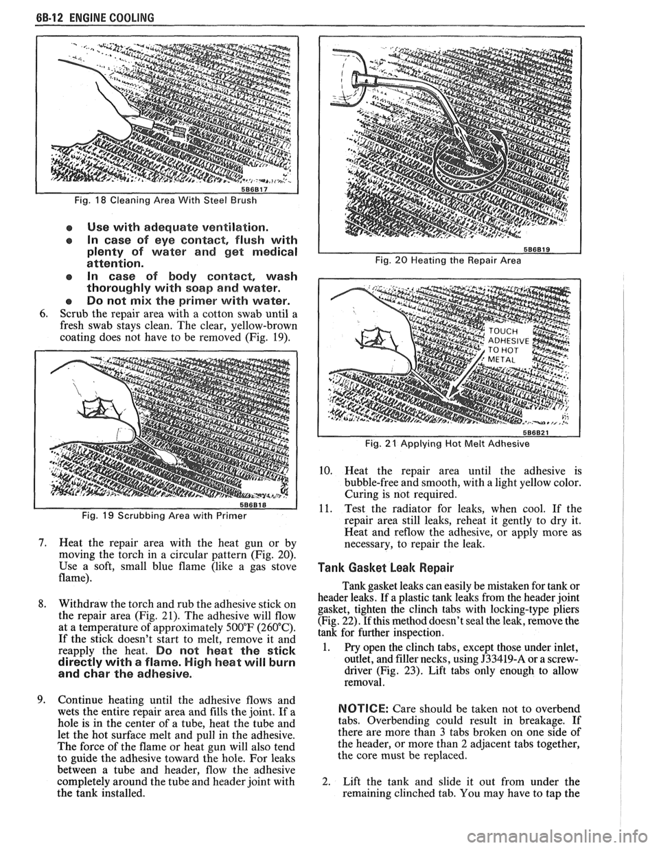
Fig. 18 Cleaning Area With Steel Brush
e Use with adequate ventilation.
In case of eye contact, flush with
plenty of water and get medical
attention.
In case of body
contact, wash
thoroughly with soap
and water.
Do not
mix the primer with water.
6. Scrub the repair area with a cotton swab until a
fresh swab stays clean. The clear, yellow-brown
coating does not have to be removed (Fig. 19).
Fig. 19 Scrubbing Area with Primer
7. Heat the repair area with the heat gun or by
moving the torch in a circular pattern (Fig. 20).
Use a soft, small blue flame (like a gas stove
flame).
8. Withdraw the torch and rub the adhesive stick on
the repair area (Fig. 21). The adhesive will flow
at a temperature of approximately 500°F (260°C).
If the stick doesn't start to melt, remove it and
reapply the heat.
Do not heat the stick
directly with
a flame. High heat will burn
and
char the adhesive.
9. Continue heating until the adhesive flows and
wets the entire repair area and fills the joint. If a
hole is in the center of a tube, heat the tube and
let the hot surface melt and pull in the adhesive.
The force of the flame or heat gun will also tend
to guide the adhesive toward the hole. For leaks
between a tube and header, flow the adhesive
completely around the tube and header joint with
the tank installed.
Fig. 20 Heating the Repair Area
I
Fig. 21 Applying Hot Melt Adhesive I
10. Heat the repair area until the adhesive is
bubble-free and smooth, with a light yellow color.
Curing is not required.
11. Test the radiator for leaks, when cool. If the
repair area still leaks, reheat it gently to dry it.
Heat and
reflow the adhesive, or apply more as
necessary, to repair the leak.
Tank Gasket beak Repair I 1
Tank gasket leaks can easily be mistaken for tank or
header leaks. If a plastic tank leaks from the header joint
gasket, tighten the clinch tabs with locking-type pliers
(Fig. 22). If this method doesn't seal the leak, remove the
tank for further inspection.
1. Pry open the clinch tabs, except those under inlet,
outlet, and filler necks, using
J33419-A or a screw-
driver (Fig.
23). Lift tabs only enough to allow
removal.
NOTICE: Care should be taken not to overbend
tabs. Overbending could result in breakage. If
there are more than
3 tabs broken on one side of
the header, or more than
2 adjacent tabs together,
the core must be replaced.
2. Lift the tank and slide it out from under the
remaining clinched tab. You may have to tap the
Page 453 of 1825
6D2-2 CRANKING SYSTEM
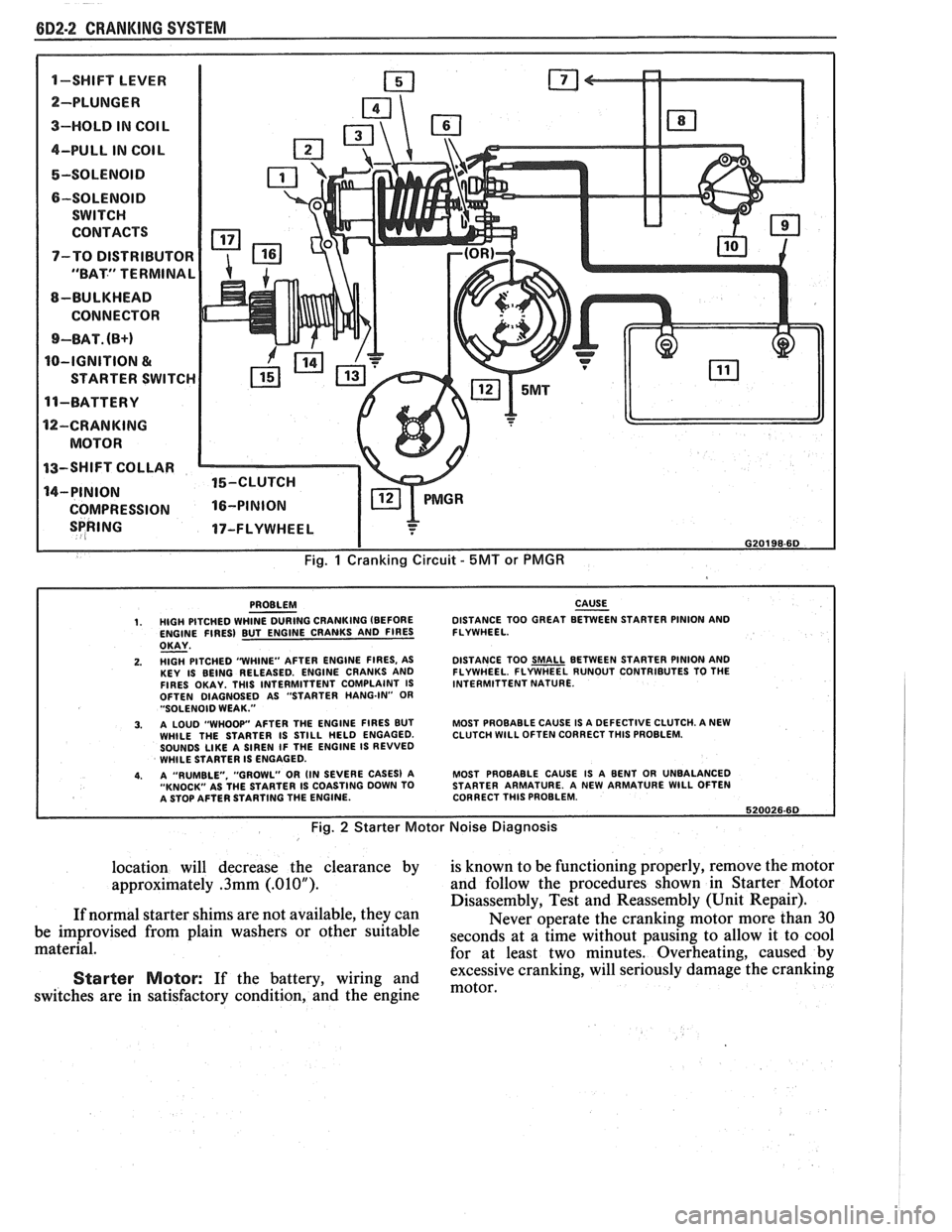
1-SWIFT LEVER m
SPRING 17-FLYWHEEL I
I G20198-6D
Fig. 1 Cranking Circuit - 5MT or PMGR
PROBLEM CAUSE - 1. HIGH PITCHED WHINE DURING CRANKING (BEFORE DISTANCE
TOO GREAT BETWEEN STARTER PINION AND
ENGINE FIRES) BUT ENGINE CRANKS AND FIRES FLYWHEEL.
OKAY - 2. HlGH PITCHED "WHINE"
AFTER ENGINE FIRES, AS
KEY IS BEING RELEASED. ENGINE CRANKS AND
FIRES OKAY. THlS INTERMITTENT COMPLAINT IS
OFTEN DIAGNOSED AS "STARTER HANG-IN"
OR "SOLENOID WEAK."
3. A LOUD "WHOOP" AFTER THE ENGINE FIRES BUT
WHILE THE STARTER IS STILL HELD ENGAGED.
SOUNDS
LIKE A SIREN IF THE ENGINE IS REVVED
WHILE STARTER IS ENGAGED.
4. A "RUMBLE. "GROWL" OR (IN SEVERE CASES) A
"KNOCK" AS THE STARTER IS COASTING DOWN TO
A STOP AFTER STARTING THE ENGINE. DISTANCE
TOO
SMALL BETWEEN STARTER PINION AND
FLYWHEEL. FLYWHEEL RUNOUT CONTRIBUTES TO THE
INTERMITTENT NATURE.
MOST PROBABLE CAUSE IS A DEFECTIVE CLUTCH. A NEW
CLUTCH
WlLL OFTEN CORRECT THlS PROBLEM.
MOST PROBABLE CAUSE IS A BENT OR UNBALANCED
STARTER ARMATURE. A NEW ARMATURE
WlLL OFTEN
CORRECT THlS PROBLEM.
620026.60
Fig. 2 Starter Motor Noise Diagnosis
location will decrease the clearance by is known to be functioning properly, remove the motor
approximately
.3mm (.01OU). and follow the procedures shown in Starter Motor
Disassembly, Test and Reassembly (Unit Repair).
If normal starter shims are not available, they can
Never operate the cranking motor more than 30
be improvised from plain washers or other suitable
seconds at a time without pausing to allow it to cool material.
for at least two minutes. Overheating, caused by
excessive cranking, will seriously
damage the cranking Starter Motor: If the battery, wiring and motor, switches are in satisfactory condition, and the engine