low oil pressure PONTIAC FIERO 1988 Service User Guide
[x] Cancel search | Manufacturer: PONTIAC, Model Year: 1988, Model line: FIERO, Model: PONTIAC FIERO 1988Pages: 1825, PDF Size: 99.44 MB
Page 61 of 1825
LlOQllD LiNE FILTER INSTALLATION
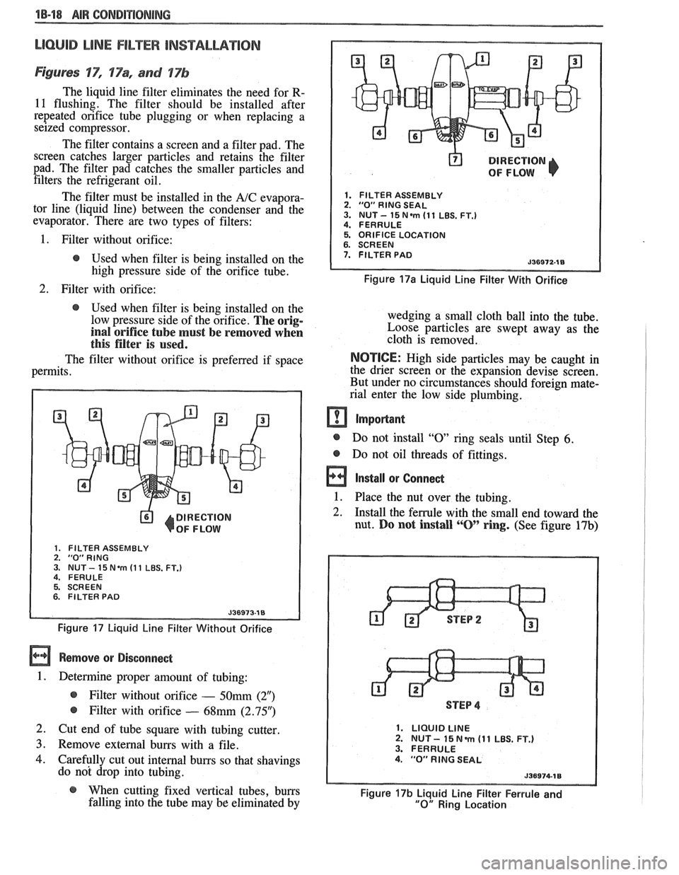
Figures 'IT", 17% and 17b
The liquid line filter eliminates the need for R-
11 flushing. The filter should be installed after
repeated orifice tube plugging or when replacing a
seized compressor.
The filter contains a screen and a filter pad. The
screen catches larger particles and retains the filter
pad. The filter pad catches the smaller particles and filters the refrigerant oil.
The filter must be installed in the
A/C evapora-
tor line (liquid line) between the condenser and the
evaporator. There are two types of filters:
@ DIRECTION
OF FLOW
1. FILTER ASSEMBLY 2. "0" RlNG SEAL 3. NUT- 15N.m (11 LBS. FT.) 4. FERRULE
1. Filter without orifice: 5. ORIFICE LOCATION
@ Used when filter is being installed on the 7. FILTER PAD
high pressure side of the orifice tube. Figure 17a Liquid Line Filter With Orifice
2. Filter with orifice:
@ Used when filter is being installed on the
low pressure side of the orifice.
The orig-
inal orifice tube must be removed when
this filter is used.
The filter without orifice is preferred if space
permits.
DIRECTION
OF FLOW
1. FILTER ASSEMBLY 2. "0"RING 3. NUT - 15 Nem (1 1 LBS. FT.) 4. FERULE
5. SCREEN
6. FILTER PAD
Figure 17 Liquid Line Filter Without Orifice
Remove or Disconnect
1. Determine proper amount of tubing:
@ Filter without orifice - 50mm (2")
@ Filter with orifice - 68mm (2.95")
2. Cut end of tube square with tubing cutter
3. Remove external burrs with a file.
4. Carefully cut out internal burrs so that shavings
do not drop into tubing. wedging a small cloth ball
into the tube.
Loose particles are swept away as the
cloth is removed.
NOTICE: High side particles may be caught in
the drier screen or the expansion devise screen.
But under no circumstances should foreign mate-
rial enter the low side plumbing.
m Important
@ Do not install "0 ring seals until Step 6.
@ Do not oil threads of fittings.
a Install or Connect
1. Place the nut over the tubing. -
2. Install the ferrule with the small end toward the
nut.
Do not install ""0' ring. (See figure 17b)
STEP 4
1. LIQUID LINE 2. NUT - 15 N m (1 1 LBS. FT.) 3. FERRULE 4. "0" RlNG SEAL
@ When cutting fixed vertical tubes, burrs Figure 17b Liquid Line Filter Ferrule and falling into the tube may be eliminated by "0" Ring Location
Page 62 of 1825
AIR CONDITIONING 18-19
3. Push the tube into the fitting, bottoming it out.
Tighten
@ Torque nut to 15 Nam (11 lbs. ft.).
4. Dissasemble the joint.
5. Lubricate the
"0" ring with clean 525 viscosity
refrigerant oil.
6. Install the
"0" ring
on the tube. (See figure 17b)
7. Reassemble joint.
Tighten
@ Torque nut to 15 Nem (11 lbs. ft.).
8. Evacuate, charge, and leak test the system.
EXPANSlON "%BE (ORIFICE) SERVlCE
Remove or Disconnect
1. Discharge system.
2. Loosen fitting
at liquid line to evaporator inlet
pipe and remove tube carefully with needle
nosed pliers or Tool
5-26549-C or equivalent.
Install or Connect
1. Install
new orifice tube with shorter screen end
in first.
2. Install
liquid line and torque to proper
specification.
3. Evacuate and charge system.
In the event that difficulty is encountered during
the removal of a restricted or plugged expansion tube
(orifice tube), the following procedure is recom-
mended:
1. Remove
as much of any impacted residue as
possible.
2. Carefully apply heat with heat gun (hair drier,
epoxy drier or equivalent) approximately
114
inch from dimples on inlet pipe. Do not over-
heat pipe.
NOTICE: If the system has a pressure switch
near the orifice tube location, it should be
removed prior to heating the pipe to avoid dam-
age to switch.
3. While applying heat, use orifice removal tool
5-26549-C to grip the orifice tube. Use a turning
motion along with a push-pull motion to loosen
to the impacted orifice tube and remove it.
4. Swab inside of evaporator inlet pipe with R-11.
5, Add
1 oz. of 525 viscosity refrigerant oil to
system.
6. Lubricate new orifice tube and O-ring with 525'
viscosity refrigerant oil and insert into inlet
pipe. Install in proper direction (smaller screen
first).
ACCUMULATOR ASSEMBLY SERVICE
The accumulator assembly for the refrigerant
system has a service replacement which includes two
(2) O-rings (for the inlet and outlet connections). The
desiccant within the shell is NOT serviced separately
- it is part of the sealed accumulator assembly. See
REFRIGERANT OIL DISTRIBUTION for condi-
tions when the accumulator must be removed from the
vehicle to measure the amount of oil present inside the
accumulator.
The accumulator assembly should ONLY be
replaced when:
1. A physical perforation to the accumulator is
found, resulting in a leak.
2. If the system is open to air for an extended
period of time (due to a front-end collision,
removed parts, ect.). The desiccant bag will be
saturated with moisture.
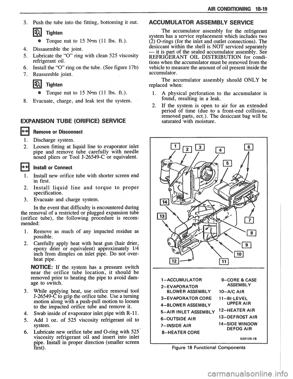
1 -ACCUMULATOR 9-CORE & CASE
2-EVAPORATOR BLOWER ASSEMBLY
10-A/C AIR
3-EVAPORATOR CORE 11-BI-LEVEL
4-BLOWER ASSEMBLY 5-AIR INLET ASSEMBLY
'IR
6-OUTSIDE AIR 13-DEFROST
AIR
7-INSIDE
AIR 14-SIDE WINDOW
DEFOG AIR
8-HEATER CORE
Figure 18 Functional Components
Page 66 of 1825
AIR CONDITIONING "18-23
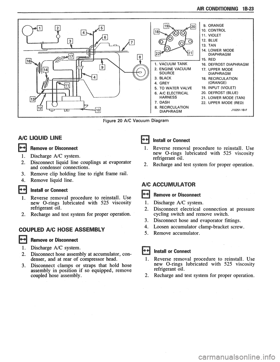
10. CONTROL
14. LOWER MODE
DIAPHRAGM
16. DEFROST DIAPHRAGM
17. UPPER MODE
DIAPHRAGM
18. RECIRCULATION
5. TO WATER VALVE 19. lfVPUT (VIOLET)
6. A/C ELECTRICAL 20. DEFROST (BLUE)
21. LOWER MODE (TAN)
22. UPPER MODE (RED)
8. RECIRCULATION
DIAPHRAGM J~OZ~~-IB-F
Figure 20 AIC Vacuum Diagram
NG LlCbUlB LINE
Remove or Disconnect
1. Discharge A!C system.
2. Disconnect liquid line couplings at evaporator
and condenser connections.
3. Remove clip holding line to right frame rail.
4. Remove liquid line.
lnstall or Conne&
1. Reverse removal procedure to reinstall. Use
new O-rings lubricated with
525 viscosity
refrigerant oil.
2. Recharge and test system for proper operation.
COUPLED NC HOSE ASSEMBLY
Remove or Disconne&
lnstall or Conne&
1. Reverse removal procedure to reinstall. Use
new O-rings lubricated with
525 viscosity
refrigerant oil.
2. Recharge and test system for proper operation.
Remove or Disconnect
1. Discharge A!C system.
2. Disconnect electrical connection at pressure
cycling switch and remove switch.
3. Disconnect hose and evaporator fittings.
4. Loosen accumulator clamp-bracket screw.
5. Remove accumulator.
1. Discharge
NC system.
2. Disconnect hose assembly at accumulator, con- Install or Connect
denser, and at rear of c6mpressor head. 1. Reverse removal procedure to reinstall. Use
3. Disconnect clamps or straps that hold hose new
O-rings lubricated with 525 viscosity
assembly in position if so equipped, remove refrigerant
oil.
coupled hose assembly.
2. Recharge and test system for proper operation.
Page 80 of 1825
W-4 AIR CONDITIONING COMPRESSOR OVERHAUL 1 Dl-l
SECTION 1 Dl
R COND NG COMPRESSOR
OVERHAUL
For Compressor REMOVAL AND INSTALLATION, see Air Conditioning Section 1B. For
DISCHARGING, ADDING OIL, EVACUATING AND CHARGING PROCEDURES FOR
A/C
SYSTEMS, see Air Conditioning Section 1B.
CONTENTS
General Description ............................... 1D1-1
Service Procedures .................................. 1D1-4
Minor Repair Procedures ....................... 1D1-4
Clutch Plate and Hub Assembly ............... 1D1-4
Clutch Rotor and Bearing: Four-Pole
Clutch
..................................................... 1D1-5
Clutch Rotor and Bearing: Six-Pole
Clutch
.......................... ... ....................... 1 D 1-7
Clutch Coil and Pulley Rim ...................... 1 D 1 - 10
Major Repair Procedures ....................... 1D1-12
Shaft Seal .................................................. 1Dl-12
Seal Leak Detection ........................... .... 1D1-12
Replacement (On Car) ........................... 1 D 1- 12
Replacement (Off Car)
........................... 1 D 1 - 13
Pressure Relief Valve
................................. 1 D 1 - 13
Nigh Pressure Cut-Off Switch
................... 1 D 1 - 13
Front Head and 0-Ring
............................ 1 D 1 - 14
Thrust and Belleville Washers
................... 1 D 1 - 16
Main Bearing
.............................................. 1 D 1- 16
Shell and 0-Ring
....................................... 1D 1- 17
Discharge Valve Plate and Retainer
......... 1 D 1 - 18
Cylinder and Shaft Assembly
.................... 1 D 1 - 19
Leak Testing (External and Internal)
........ 1D1- 19
Special Tools ..................................... ... .. 1D1-21
GENERAL DESCRIPTION
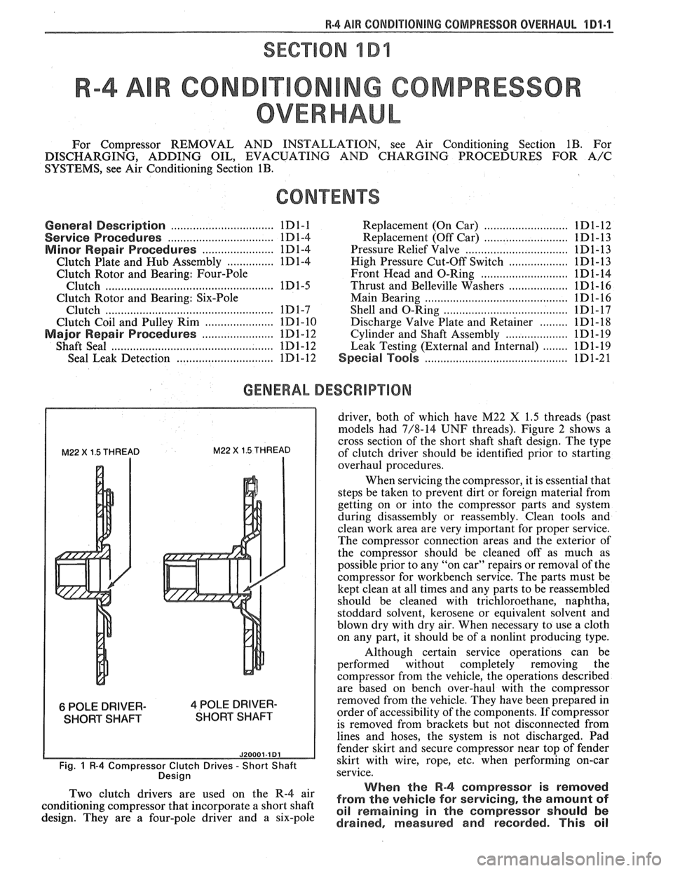
M22 X 1.5 THREAD M22 X 1.5 THREAD
6 POLE DRIVER- 4 POLE DRIVER-
SHORT SHAFT SHORT SHAFT
J20001.1 Dl
Fig. 1 R-4 Compressor Clutch Drives - Short Shaft
Desian
driver, both of which have M22 X 1.5 threads (past
models had 7/8-14
UNF threads). Figure 2 shows a
cross section of the short shaft shaft design. The type
of clutch driver should be identified prior to starting
overhaul procedures.
When servicing the compressor, it is essential that
steps be taken to prevent dirt or foreign material from
getting on or into the compressor parts and system
during disassembly or reassembly. Clean tools and
clean work area are very important for proper service.
The compressor connection areas and the exterior of
the compressor should be cleaned off as much as
possible prior to any "on car" repairs or removal of the
compressor for workbench service. The parts must be
kept clean at all times and any parts to be reassembled
should be cleaned with trichloroethane, naphtha,
stoddard solvent, kerosene or equivalent solvent and
blown dry with dry air. When necessary to use a cloth
on any part, it should be of a nonlint producing type.
Although certain service operations can be
performed without completely removing the
compressor from the vehicle, the operations described
are based on bench over-haul with the compressor
removed from the vehicle. They have been prepared in
order of accessibility of the components. If compressor
is removed from brackets but not disconnected from
lines and hoses, the system is not discharged. Pad
fender skirt and secure compressor near top of fender
skirt with wire, rope,
etc, when performing on-car
service.
., When the R-4 compressor is removed Two 'lutch drivers are wed On the R-4 air from the vehicle for servicing, the amount of conditioning compressor that incorporate a short shaft oil remaining in the should be design. They are a four-pole driver and a six-pole drained, measured and recorded. This oil
Page 83 of 1825
181-4 R-4 ABR CONDITIONING COMPRESSOR OVERHAUL
SERVICE PROCEDURES
MINOR REPAIR PROCEDURES
THE FOLLOWING OPERATIONS TO THE
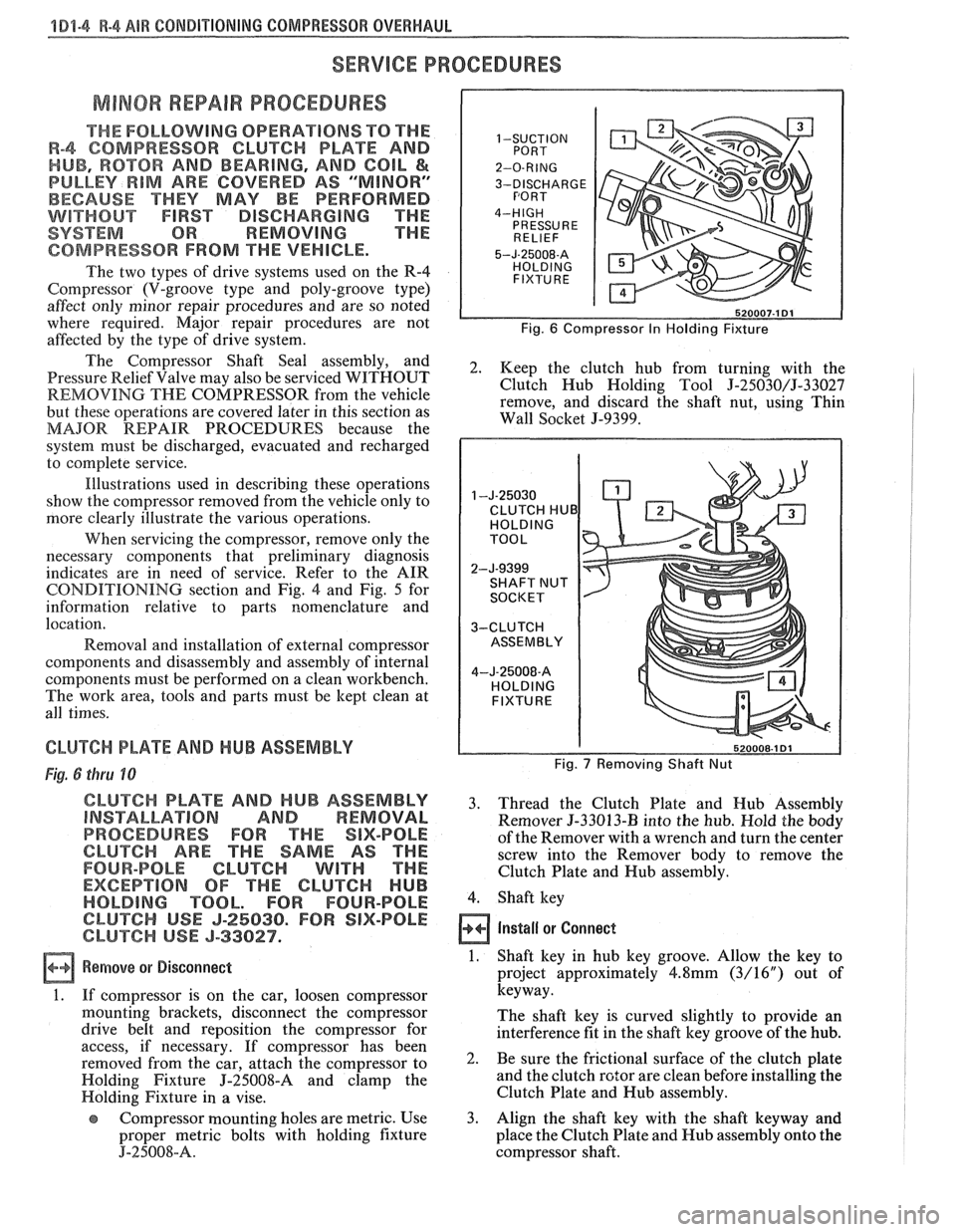
R-4 COMPRESSOR CLUTCH PLATE AND 1 -SUCTION
HUB, ROTOR AND BEARING, AND COIL &
PULLEY RIM ARE COVERED AS 'WINOR" 3-DISCHARGE
BECAUSE THEY MAY BE PERFORMED
WITHOUT FIRST DISCHARGING THE
SYSTEM OR REMOVING THE
COMPRESSOR FROM THE VEHICLE. 5-~-25008-~
The two types of drive systems used on the R-4
Compressor (\I-groove type and poly-groove type)
affect only minor repair procedures and are so noted
where required. Major repair procedures are not
Fig. 6 Compressor In Holding Fixture affected by the type of drive system.
The Shaft and 2. Keep the clutch hub from turning with the
Pressure Relief Valve may also be serviced WITHOUT
REMOVING THE COMPRESSOR from the vehicle Clutch
Hub Holding Tool 5-25030/J-33027
remove, and discard the shaft nut, using Thin
but these operations are covered later in this section as
MAJOR REPAIR PROCEDURES because the Wall Socket
5-9399.
system must be discharged, evacuated and recharged
to complete service.
Illustrations used in describing these operations
show the compressor removed from the vehicle only to
more clearly illustrate the various operations.
CLUTCH HUB
When servicing the compressor, remove only the
necessary components that preliminary diagnosis
indicates are in need of service. Refer to the AIR
CONDITIONING section and Fig.
4 and Fig. 5 for
information relative to parts nomenclature and
location.
Removal and installation of external compressor
components and disassembly and assembly of internal
components must be performed on a clean workbench.
The work area, tools and parts must be kept clean at
all times.
CLUTCH PLATE AND HUB ASSEMBLY Fig. 7 Removing Shaft Nut Fig. 6 thru 10
CLUTCH PLATE AND HUB ASSEMBLY 3. Thread the Clutch Plate and Hub Assembly INSTALLATION AND REMOVAL Remover 5-33013-I3 into the hub. Hold the body
PROCEDURES FOR THE SIX-POLE of the Remover with a wrench and turn the center
CLUTCH ARE THE SAME AS THE screw into the Remover body to remove the
FOUR-POLE CLUTCH WITH THE Clutch Plate and Hub assembly.
EXCEPTION OF THE CLUTCH HUB
HOLDING TOOL. FOR FOUR-POLE 4. Shaft key
CLUTCH USE J-25030. FOR SIX-POLE
CLUTCH USE J-33027. Install or Connect
a Remove or Disconnect 1. Shaft key in hub key groove. Allow the key to
project approximately
4.8mm (3/16") out of
1. If compressor is on the car, loosen compressor keyway.
mounting brackets, disconnect the compressor
The shaft key is curved slightly to provide an
drive belt and reposition the compressor for
interference fit in the shaft key groove of the hub.
access, if necessary. If compressor has been
removed from the car, attach the compressor to 2. Be Sure the frictional surface of the clutch plate
Holding Fixture
J-'25008-8 and clamp the and
the clutch rotor are clean before installing the
Holding Fixture
in a vise. Clutch
Plate and Hub assembly.
Compressor mounting holes are metric. Use 3.
Align the shaft key with the shaft keyway and
proper metric bolts with holding fixture place the Clutch Plate and Hub assembly onto the
J-25008-A. compressor shaft.
Page 91 of 1825
4 Dl-I 2 R-4 AIR CONDITIONING COMPRESSOR OVERHAUL
MAJOR REPAIR PROCEDURES
Service repair procedures to the
Compressor Shaft Seal,
Pressure Relief Valve
or disassembly
of the Internal Compressor
Cylinder and Shaft Assembly are considered
"MAJOR" SINCE THE REFRIGERATION
SYSTEM MUST BE DISCHARGED,
EVACUATED AND RECHARGED to complete
service and/or because major internal
operating and sealing components of the
compressor are being disassembled and
serviced.
When replacing the shaft seal assembly or
pressure relief valve, even if the compressor remains on
the vehicle during the operation, it will be necessary to
discharge the system of refrigerant (see Section
1B).
Other than clutch repair procedures, the same holds
true for any disassembly of the compressor.
If the compressor shell, front head or cylinder
and shaft assembly are to be serviced or replaced, the
oil in the compressor must be drained, measured and
replaced (see Section
1B) to determine addition of
proper oil quantity to new assembly.
A clean workbench, preferably covered with a
sheet of clean paper, orderliness in the work area and
a place for all parts being removed and replaced is of
great importance, as is the use of the proper, clean
service tools.
NOTICE: Any attempt to use make-shift or
inadequate equipment may result in damage
and/or improper compressor operation.
All parts required for servicing the internal
compressor are protected by a preservation process and
packaged in a manner which will eliminate the
necessity of cleaning, washing or flushing of the parts.
The parts can be used in the internal assembly just as
they are removed from the service package.
Seals and
protective packaging should be left in tact un
ti1 just
prior to installation.
SI-IAFT SEAL
Fig. 35 thru 40
Shaft Seal Design
The shaft seal is a one piece design.
Seal Leak Detection
A shaft seal should not be changed because of an
oil-line on the hood insulator. The Seal is designed to
seep some oil for lubrication purposes. Only change a
Shaft Seal when a leak is detected by evidence of oil
sprayed in large amounts and then only after actual
refrigerant leakage is found by using an approved leak
Detector such as J-29547 or equivalent.
Should an R-4 compressor shaft seal ever have to
be replaced, the accumulator in this R-4 system must
also be removed from the vehicle. The oil in the
accumulator then must be drained, measured and
replaced according to the directions in Section
1B to
determine oil loss.
On-Car
Remove
or Disconnect
1. Discharge A/C system
2. Loosen and reposition compressor in mounting
brackets
3. Clutch Plate and Hub assembly
4. Shaft seal seat retainer ring, using Snap Ring
Pliers J-5403-A
5. Thoroughly clean inside of compressor neck area
and O-ring groove surrounding the shaft, the
exposed portion of the seal seat and the shaft
itself. Any dirt or foreign material getting into
compressor may cause damage.
6. Remove Lip Seal:
e Fully engage the knurled tangs of Seal
Remover-Installer J-23 128-A into the
recessed portion of the Seal by turning the
handle clockwise. Remove the Seal from the
compressor with a rotary-pulling motion.
Discard the Seal. The handle must be
hand-tightened securely. Do not use a
wrench or pliers.
7. Discard the seal seat O-ring from the compressor
neck using 0-Ring Remover J-9553-01.
8. Recheck the shaft and inside of the compressor
neck and O-ring groove for dirt or foreign
material and be sure these areas are perfectly
clean before installing new parts.
Inspection
Seals should not be reused. Always use a new
specification service seal kit on rebuild. Care should be
taken to prevent damage to the lip of the one piece seal.
Make sure that the Seal Seat and Seal Lip are free of
lint and dirt that could damage the seal surface or
prevent sealing.
On-Car
Install
or Connect
1. Dip
the new seal O-ring in clean 525 viscosity
refrigerant oil and assemble onto 0-Ring
Installer J-33011.
2. Insert
the 0-Ring Installer
5-3301 1 completely
down into the compressor neck until the Installer
"bottoms." Lower the moveable slide of the
0-Ring Installer to release the 0-Ring into the
seal seat O-ring lower groove. (The compressor
neck top groove is for the shaft seal retainer ring.)
Rotate the Installer to seat the O-ring and remove
the Installer.
3. Prepare Lip Seal:
Assemble seal to Seal Installer J-23128-A,
by turning handle clockwise, and then push
Seal Protector J-34614, into seal lip. The
stamped steel case side of the lip seal must
be engaged with knurled tangs of installer so
that flared-out side of lip seal is facing and
installed towards the compressor.
4. Install Lip Seal:
Page 92 of 1825
R-4 AIR CONDITIONING COMPRESSOR OVERHAUL 101-13.
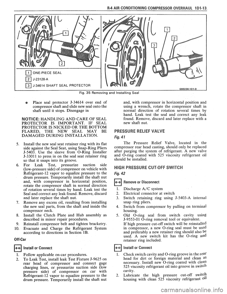
ONE-PIECE SEAL
J-34614 SHAFT SEAL PROTECTOR I G60230-181.8
Fig. 35 Removing and Installing Seal
Place seal protector 9-34614 over end of
compressor shaft and slide new seal onto the
shaft until it stops. Disengage in
NOTICE: HANDLING AND CARE OF SEAL
PROTECTOR IS IMPORTANT. IF SEAL
PROTECTOR IS NICKED OR THE BOTTOM
FLARED, THE NEW SEAL
MAY BE
DAMAGED DURING INSTALLATION.
5. Install the new seal seat retainer ring with its flat
side against the Seal Seat, using Snap-Ring Pliers
5-5403. Use the sleeve from O-Ring Installer
5-3301 1 to press in on the seal seat retainer ring
so that it snaps into its groove.
6. For Leak Test, pressurize suction side
(low-pressure side) of compressor on vehicle with
Refrigerant-12 vapor to equalize pressure to the
drum pressure. Temporarily install the shaft nut
and, with compressor in horizontal position,
rotate the compressor shaft in normal direction
of rotation several times by hand. Leak test the
Seal and correct any leak found. Remove, discard
and later replace the shaft nut.
7. Remove any excess oil, resulting from installing
the new seal parts, from the shaft and inside the
compressor neck.
8. Install the Clutch Plate and Hub assembly as
described in minor repair procedures.
9. Reinstall compressor belt and tighten bracketry.
10. Evacuate and Charge the Refrigerant System
according to directions in Section
1B.
Off-Car
Install or
Connect
1. Follow applicable on-car procedures.
2. To Leak Test, install leak Test Fixture 5-9625 on
rear head of compressor and connect gage
charging lines, or pressurize suction side (low
pressure side) of compressor on car with
Refrigerant-12 vapor to equalize pressure to the
drum pressure. Temporarily install the shaft nut and,
with compressor in horizontal position and
using a wrench, rotate the compressor shaft in
normal direction of rotation several times by
hand.
Leak test the seal and correct any leak
found. Remove, discard and later replace with a
new shaft nut.
PRESSURE RELIEF VALVE
Fig. 4 1
The Pressure Relief Valve, located in the
compressor rear head casting, should only be replaced
after purging the system of refrigerant,
A new valve
and O-ring coated with 525 viscosity refrigerant oil
should be installed.
HIGH PRESSURE CUT-OFF SWITCH
Fig. 42
Remove or Disconnect
1. Discharge A/C system
2. Electrical connector at switch
3. Switch retaining ring using
J-5403-A internal
snap ring pliers.
4. Switch from compressor by pulling on terminal
housing.
5. Old O-ring seal from switch cavity using
J-9553-01 O-ring removal tool or equivalent.
If high pressure cut-off switch will be reinstalled.
in compressor, a new O-ring seal must be
used
and preferably a new retainer ring should also be
used. A new switch kit has the O-ring and
retainer ring included.
install or Connect
1.
Check switch cavity and O-ring groove in the rear
head for dirt or foreign material and clean as
necessary. Install new O-ring coated with cleall
525 viscosity refrigerant oil into groove in switch
cavity.
2. Lubricate the high pressure cut-off
switgh
housing with clean 525 viscosity refrigerant
Page 98 of 1825
R-4 818 CONDITIONING COMPRESSOR OVERHAUL 1D1-19
retainers are to be removed, remove two sets and
then rotate compressor and Holding Fixture
J-25008-A in vise for access to the remaining two
valve plates and retainers.
Install or Connect
1. Install Discharge Valve Plates and/or Retainers.
Reposition compressor and Holding Fixture in
vise as necessary for access.
Valve plates must
be tight
following retainer assembly.
2. Reinstall compressor Shell as described in
SHELL AND O-RINGS replacement
procedures.
3. Evacuate and charge the refrigerant system
according to the directions in Section
1B.
CYLINDER AND SHAFT ASSSEMBLY
Remove or Disconnect
Discharge the refrigerant system according to the
directions in Section
1B.
Remove the Clutch Plate and Hub assembly as
described in CLUTCH PLATE AND HUB
removal procedure.
Perform Steps
1 through 4 of CLUTCH ROTOR
AND BEARING removal procedure but do not
loosen or remove the pulley rim mounting screws.
Remove the Clutch Rotor and Bearing, Clutch
Coil and Pulley Rim as an assembly. Be careful
not to drop the Puller Guide J-25031, when
removing the assembly.
Remove the shaft seal as described in SHAFT
SEAL removal procedure.
Remove the front head as described in FRONT
HEAD REMOVAL procedure.
Remove the thrust and belleville washers as
described in THRUST AND BELLEVILLE
WASHERS removal procedures.
Remove the compressor shell as described in
SHELL removal procedure.
Remove the discharge valve plate and retainer as
described in DISCHARGE VALVE PLATE
AND RETAINER removal procedure.
Remove the high pressure relief valve as
described in
HIGH PRESSURE RELIEF
VALVE REMOVAL PROCEDURE.
L
Install or Connect
1. Replace above parts in opposite order.
2. Evacuate and charge the refrigerant system
according to the directions in Section
1B.
LEAK TESVING (EXTERNAL AND INTERNAL)
Bench-Check Procedure
1. Install Test Plate J-9625-A on Rear Head of
compressor.
2. Attach center hose of Manifold Gage Set on
Charging Station to a refrigerant drum standing
in an upright position and open valve on drum.
3. Connect Charging Station high and low pressure
lines to corresponding fittings on Test Plate J-9625-A, using
5-5420 Gage
Adapters if hoses
are not equipped with valve depressors.
Suction port (low-side) of compressor has
large internal opening. Discharge port
(hi-side) has smaller internal opening into
compressor.
Open low-pressure control, high-pressure control
and refrigerant control on Charging Station to
allow refrigerant vapor to flow into compressor.
Using a Leak Detector, check for leaks at
Pressure Relief Valve, compressor shell to
cylinder, compressor front head seal, and
compressor Shaft Seal. After checking, shut off
low pressure control and high pressure control on
Charging Station.
If an external leak is present, perform the
necessary corrective measures and recheck for
leaks to make certain the leak has been corrected.
Loosen the Manifold Gage hose connections to
the Gage Adapters J-5420 connected to the low
and high sides and allow the vapor pressure to
release from the compressor.
Disconnect both Gage Adapters
5-5420 from the
Test Plate J-9625-A.
Rotate the complete compressor assembly (not
the crankshaft or drive plate hub) slowly several
turns to distribute oil to all cylinder and piston
areas.
Install a shaft nut on the compressor crankshaft
if the drive plate and clutch assembly are not
installed.
Using a box-end wrench or socket and handle,
rotate the compressor crankshaft or clutch drive
plate on the crankshaft several turns to ensure
piston assembly to cylinder wall lubrication.
Connect the Charging Station high pressure line
or a high pressure gage and Gage Adapter J-5420
to the Test Plate J-9625-A high side connector.
Attach an Adapter
9-5420 to the suction or low
pressure port of the Test Plate
J-9625-19 to open
the Schrader-type valve.
Oil will drain out of the compressor suction port
adapter if the compressor is positioned with the
suction port downward.
Attach the compressor to the Holding Fixture
J-25008-A using metric mounting screws. Clamp
the compressor Holding Fixture in a vise so that
the compressor can be manually turned with a
wrench.
Using a wrench, rotate the compressor crankshaft
or drive plate hub ten complete revolutions at a
speed of approximately one-revolution per
second.
Turning the compressor at less than
one-revolution per second can result in a lower
pump-up pressure and disqualify a good pumping
compressor.
Observe the reading on HIGH pressure gage at
the completion of the tenth revolution of the
compressor. The pressure reading for a good
pumping compressor should be 344.75
kPa (50 p.
s.i.) or above. A pressure reading of less than 3 10.
275 kPa (45 p.s.i.) would indicate one or more
Page 99 of 1825
101.20 R-4 AIR CONDITIONING COMPRESSOR OVERHAUL
suction and/or discharge valves leaking, an
internal leak or an inoperative valve, and the
compressor should be disassembled and checked
for cause of leak. Repair as needed, reassemble
and repeat the pump-up test. Externally leak test.
When the pressure pump-up test is completed,
release the air pressure from the HIGH side and
remove the Gage Adapters J-5420 and Test Plate
J-9625-A. 18. On the R-4 compressor, tilt the compressor so
that the compressor suction and discharge ports
are down. Drain the oil from the compressor.
19. Allow the compressor to drain for
10 minutes,
then charge with the proper amount of oil. The
oil may be poured into the suction port.
If further assembly or processing is required, a
shipping plate or Test Plate J-9625-A should be
installed to keep out air, dirt and moisture until
the compressor is installed.
Page 103 of 1825
2B-2 BUMPERS
REAR BUMPER FASCIA
Removal
Place a jack stand under fascia before removing
bolts to prevent it from dropping down when fascia
attaching bolts are removed. Fascia will pivot on the
opposite end when one end is disconnected. Do not
rotate energy absorber any more than necessary to
align mounting holes.
1. Remove fascia attaching bolts and fascia to
fender attaching screws on right and left side, and
remove fascia and spacers.
2. If energy absorber is to be replaced, remove the
bolts and nuts from the front of the unit and the
nut from the stud at the rear. The stud at the rear
of the absorber is attached to a bracket in the
frame. Remove the bolt holding this bracket in
the frame to remove the absorber.
Installation
1. Install energy absorber if removed.
2. Support fascia during installation to prevent
rotation of energy absorbers.
3. Install spacers and bolts at fascia to energy
absorber brackets.
4. Install fascia to fender attaching screws.
5. Check for proper clearance.
6. If adjustment is required to align the fascia, use
shims as necessary. Vertical and lateral
adjustment can be made at slots in fascia and
absorber brackets. Torque all bolts and nuts. (See
Specifications.)
FRONT BUMPER
Removal
1. Remove
front end fascia as shown in Section 2C.
2. Remove bumper barlenergy absorber assembly
from body.
3. If energy absorber must be replaced, drill out pop
rivets, and install new absorber with nuts, bolts,
and locking washers.
4. To install, reverse above procedure.
REAR BUMPER
Removal
1. Remove left hand rear quarter trim panel.
2. Remove right hand rear quataer trim panel.
3. Remove spare tire assembly.
4. Remove rear center trim panel.
5. Remove right tail light assembly.
6. Remove left tail light assembly.
7. Remove tail light center piece.
8. Remove bumper cover lower retainers.
9. Remove right-side bumper cover fasteners from
inside of compartment.
10. Remove left side bumper cover fasteners from
inside of compartment.
11. Remove bumper cover upper retainers.
12. Remove cover.
13. To dissasemble impact bar, proceed as follows:
a. Remove bolts attataching impact bar to
rear end panel.
b. Remove rivets retaining pad to impact
bar.
14. To install, reverse above procedure.
BUMPER ENERGY ABSORBING UNITS
The absorbing capability for both front and rear
bumper systems is achieved through two energy
absorbing devices in each bumper. These units convert
the energy of an impact into heat and restoration. The
energy absorbing device consists of two main
subassemblies: the piston tube assembly and the
cylinder tube assembly. The piston tube assembly is
filled with an inert gas under pressure and consists of
a bumper bracket, piston tube, orifice, seal, piston seal,
piston, and stop-ring. The cylinder tube assembly is
filled with a hydraulic fluid and consists of a frame
bracket, cylinder tube, mounting stud, and metering
pin.
Upon impact, as the energy absorber is collapsed,
the hydraulic fluid in the cylinder tube is forced into
the piston tube through the orifice. The metering pin
controls the rate at which this fluid passes from the
cylinder tube through the orifice and into the piston
tube. This controlled passage of fluid provides the
energy absorbing action.
The hydraulic fluid that is forced from the
cylinder tube into the piston tube displaces the floating
piston, compressing the gas behind the floating piston.
After impact, the pressure of the compressed gas
behind the floating piston forces the hydraulic fluid
back into the cylinder tube assembly, extending the
unit to its normal position.
Some front and rear bumpers (J and
F Models)
use a plastic honeycomb pad energy absorber (except
J wagon rear bumper). This energy absorber will
compress on impact, and both the energy absorber and
the urethane fascia will return to their original shape.
The energy absorber pad has no moving parts.
The J wagon rear bumper system uses a hydraulic
energy absorbing unit, more commonly known as a
"minisorber".
TESTING FRONT OR REAR ENERGY
ABSORBER OPERATION
The right and left energy absorbing devices are to
be diagnosed separately. The following checks are to be
made on each unit:
1. Leakage
Some oil wetting may be visible due to the grease
packed in the crimp recess. Therefore, a stain or trace
of oil on the piston tube near the crimp is normal.
However, if oil is dripping continuously from the crimp
or the stud end of the unit, a leak is indicated and the
unit should be replaced.