low oil pressure PONTIAC FIERO 1988 Service Owner's Manual
[x] Cancel search | Manufacturer: PONTIAC, Model Year: 1988, Model line: FIERO, Model: PONTIAC FIERO 1988Pages: 1825, PDF Size: 99.44 MB
Page 229 of 1825
3D-8 REAR SUSPENSION
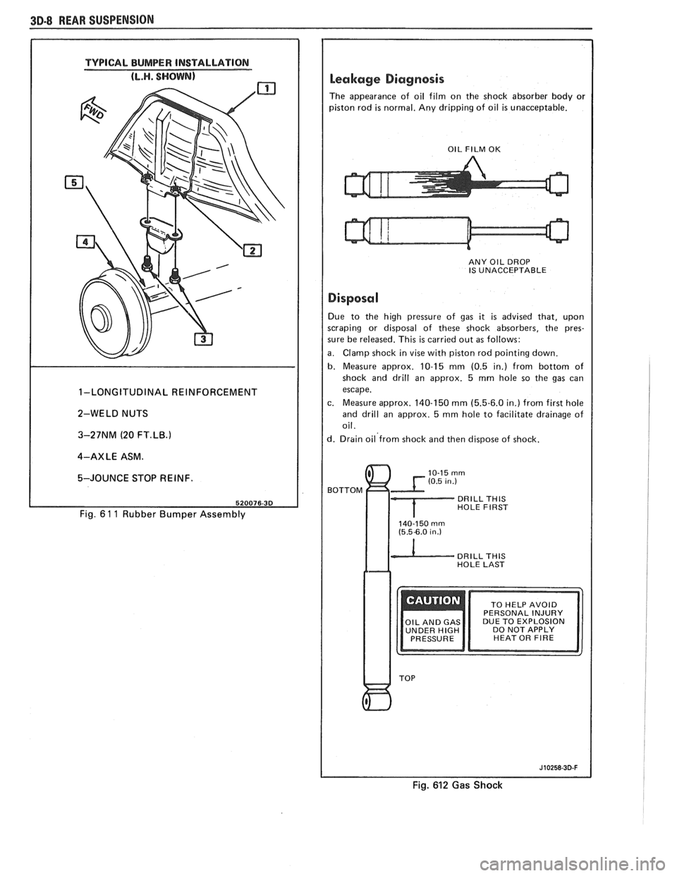
TYPICAL BUMPER INSTALLATION
1-LONGITUDINAL REINFORCEMENT
2-WELD NUTS
3-27NM (20
FT.LB.1
4-AXLE ASM.
5-JOUNCE STOP REINF.
Fig. 6 1 1 Rubber Bumper Assembly
Leakage Diagnosis
The appearance of oil film on the shock absorber body or
piston rod
is normal. Any dripping of oil is unacceptable.
I OIL FILM OK I
ANY OIL DROP
IS UNACCEPTABLE
I Disposal I Due to the high pressure of gas it is advised that, upon
scraping or disposal of these shock absorbers, the pres-
sure be released. This
is carried out as follows:
a. Clamp shock in vise with piston rod pointing down.
b. Measure approx. 10-15 mm (0.5 in.) from bottom of
shock and drill an approx. 5
mm hole so the gas can
escape.
c. Measure approx. 140-150
mm (5.5-6.0 in.) from first hole
and drill an approx. 5
mm hole to facilitate drainage of
oil.
d. Drain oil'from shock and then dispose of shock.
BOTTOM
DRILL THlS HOLE FIRST
140-150 rnrn (5.5-6.0 in.)
DRILL THlS HOLE LAST
DUE TO EXPLOSION
UNDER
HIGH DO NOT APPLY
HEAT OR FIRE
Fig. 612 Gas Shock
Page 240 of 1825
TIRES AND WHEELS 3E-9
Another method is to dismount the tire and
rotate it 180 degrees on the rim. It is important that
this be done on tire and wheel assemblies which are
known to be causing a vibration as it is just as likely to
cause good assemblies to vibrate.
Refer to Section 3, "Vibration Diagnosis" for
more details.
ALUMINUM WHEEL CLEANING
Aluminum wheels should be cleaned and waxed
regularly. Do not use abrasive cleaners, as they could
damage the protective coating.
ALUMINUM WHEEL HUB CAP
Remove or Disconnect
1. Tire and wheel assembly
2. Place a block of wood approximately 2" in
diameter with a squared off end against the back
surface of the cap.
A sharp hammer biow on the
block of wood will
remove the cap.
Install or Connect
1. Place
cap into position at wheel opening and
place a block of wood at least three inches in
diameter against cap face. Install cap by striking
block of wood with hammer.
2. Tire and wheel assembly
NOTICE: Failure to hit cap squarely without the
load distributed evenly could result in permanent
damage to the cap.
ALUMINUM WHEEL POROSITY REPAIR
1. Remove tire and wheel assembly.
2. Locate
leaking areas by inflating tire to 345
kPa
(50 psi) and dipping tire and wheel assembly into
a water bath.
3. Mark
leak areas and remove tire from wheel.
4. Scuff inside surface at leak area with 80 grit
sandpaper and clean area with general purpose
cleaner such as
3M #08984 or equivalent.
5. Apply 1/8" thick layer of adhesive/sealant P/N
1052366 or equivalent to leak area and allow
twelve hours of drying time.
6. Mount tire on wheel, pressurize to 345 kPa (50
psi) and check for leaks.
CAUTION: To avoid serious personal
injury, do not stand over tire when
inflating. Bead may break when bead
snaps over safety hump. Do not
exceed
275 kPa (40 psi) pressure
when inflating any tire if beads are
not seated.
14 275 kPa (40 psi)
pressure will not seat beads, deflate,
relubricate the beads and reinflate.
Overinflation may cause the bead to
break and cause serious personal
injury.
7. Adjust
tire pressure to meet specifications.
8. Balance tire and wheel assembly.
9. Install tire and wheel assembly.
ALUMINUM WHEEL REFINISHING
A protective clear or color coating is applied to
the surface of original equipment cast aluminum
wheels.
A surface degradation condition can begin to
develop if frequent, repeated automatic car wash
cleaning abrades or wears off the factory applied
protective coating. This can happen at some automatic
car wash facilities using aggressive silicon carbide
tipped tire brushes
to clean white walls and tires. Once
the protective coating is
damaged, exposure to caustic
cleaners and/or road salt further causes surface
degradation. The following procedure details how to
strip, clean
and recoat aluminum wheels that are
affected by these conditions.
Required Materials:
A~nchern Alumi Prep #33 - stock
#DX533 or equivalent - cleaning and
conditioning chemical for aluminum.
Amchem Alodine
# 1001 - stock #DXSOT
or equivalent - coating chemical for
aluminum.
Ditzler Delclear Acrylic Urethane Clear
-
stock #DAU-75 or equivalent.
Ditzler Delthane Ultra-Urethane Additive
- stock DXR-80 or equivalent.
Service Procedure:
1. Mark wheel and wheel stud for position on car.
2. Remove tire and wheel assembly from car.
3. Mark location of outboard weights and remove.
4. Wash wheel inside and out with water base all
purpose cleaner. Remove grease and oil with
solvent cleaner.
5. Mask off tire prior to painting.
6. Select and follow the correct procedure,
"Aluminum Damage on Wheel Surface" or
"Clear Coat Damage on Unpainted Wheels".
7. Replace wheel weights with nylon coated
weights.
8. Install tire and wheel assembly on car and tighten
wheel nuts to proper torque.
Accent Color Preparation
1. Sand over painted areas that will not require
recoloring with 400 grit (wet or dry) to promote
adhesion of clear coat.
Aluminum Damage on Wheel Surface
1. Mount tire and wheel on brake lathe and spin
slowly.
2. Sand wheel with backing block or pad by holding
abrasive flat to surface of wheel and moving
slowly back and forth from center to outer edge
to remove damage. Use the following sandpaper
grits in the order listed.
A. Sand with 80 grit
B. Sand with 150 grit
C. Sand with 240 grit
3. Continue with "Recoating Procedure."
Page 286 of 1825
REAR AXLE 48-13
2. Drive
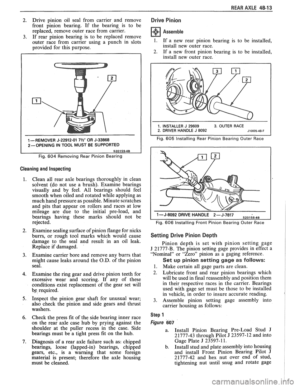
pinion oil seal from carrier and remove
front pinion bearing. If the bearing is to be
replaced, remove outer race from carrier.
3. If rear pinion bearing is to be replaced remove
outer race from carrier using a punch in slots
provided for this purpose.
1 -REMOVER J-22912-01 7%" OR J-33868
2-OPENING IN TOOL MUST BE SUPPORTED
Fig.
604 Removing Rear Pinion Bearing
Cleaning and Inspecting
1. Clean
all rear axle bearings thoroughly in clean
solvent (do not use a brush). Examine bearings
visually and by feel. All bearings should feel
smooth when oiled and rotated while applying as
much hand pressure as possible. Minute scratches
and pits that appear on rollers and races at low
mileage are due to the initial pre-load, and
bearings having these marks should not be
rejected.
2. Examine sealing surface of pinion flange for nicks
burrs, or rough tool marks which would cause
damage to the seal and result in an oil leak.
Replace if damaged.
'
3. Examine carrier bore and remove any burrs that
might cause leaks around the O.D. of the pinion
seal.
4. Examine the ring gear and drive pinion teeth for
excessive wear and scoring. If any of these
conditions exist replacement of the gear set will
bs required.
5. Inspect the pinion gear shaft for unusual wear;
also check the pinion and side gears and thrust
washers.
6. Check the press fit of the side bearing inner race
on the rear axle case hub by prying against the
shoulder at the puller recess in the case. Side
bearings must be a tight press fit on the hub.
7. Diagnosis of a rear axle failure such as: chipped
bearings, loose (lapped-in) bearings, chipped
gears, etc., is a warning that some foreign
material is present; therefore the axle housing
must be cleaned.
Drive Pinion
Assemble
I. If a new rear pinion bearing is to be installed,
install new outer race.
2. If a new front pinion bearing is to be installed,
install new outer race.
Fig. 605 Installing Rear Pinion Bearing Outer Race
1- J-8092 DRIVE H-,.wb- 6
Fig. 606 Installing Front Pinion Bearing Outer Race
Setting Drive Pinion Depth
Pinion depth is set with pinion setting gage
J 21777-B. The pinion setting gage provides in effect a
"Nominal" or "Zero" pinion as a gaging reference.
Set up pinion setting gage as follows:
1. Make certain all gage parts are clean.
2. Lubricate front and rear pinion bearings which
will be used in final reassembly and position them
in their respective races in the carrier. Bearings
used with gage set must be those to be installed
in vehicle, in order to insure accurate reading.
3. Assemble pinion setting gage assembly into
carrier housing as follows:
Step 1
Figure 607
a.
Install Pinion Bearing Pre-Load Stud J
21777-43 through Pilot J 23597-12 and into
Gage Plate
J 23597- 11.
b. Install stud and plate assembly into housing
and install Front Pinion Bearing Pilot
J
21777-42 and hex nut over end of stud,
tightening nut until snug and rotate gage
Page 296 of 1825
BRAKES 5-3
DIAGNOSIS AND INSPECTION
BRAKE SYSTEM TESTING
(Figures
2 through 4)
Brakes should be tested on dry, clean, reasonably
smooth and level roadway. A true test of brake performance
cannot be made if the roadway is wet, greasy or covered
with loose dirt so that all tires do not grip the road equally.
Testing will also be affected if the roadway is crowned
which would throw the weight of the car toward the wheels
on one side. If the roadway is too rough, the wheels will tend
to bounce. Test brakes at different car speeds with both light and
heavy pedal pressure, avoid locking the brakes and sliding
the tires. Locked brakes and sliding tires do not indicate
brake efficiency, because heavily braked, but turning
wheels will stop the car in less distance than locked brakes.
More tire-to-road friction is present with a heavily braked
turning tire than with a sliding tire. The brake system is designed and balanced to avoid
locking the wheels, except at very high deceleration levels.
The shortest stopping distance and best control is achieved
without brake lock-up.
Because of high deceleration capability, a firmer pedal
may be felt at higher deceleration levels.
External Conditions That Affect Brake Performance
1. Tires. Tires having unequal contact and grip on road
will cause unequal braking. Tires must be equally
inflated and tread pattern of right and left tires must
be approximately equal.
2. Car Loading. A heavily loaded car requires more
braking effort. When a car has unequal loading, the
most heavily loaded wheels require more braking
power than others.
3. Wheel Alignment. Misalignment of the wheels, par-
ticularly excessive camber and caster, will cause the
brakes to pull to one side.
4. Front Wheel Bearings. A loose front wheel bearing
BRAKE FLUID LEAKS
With engine running at idle and the transmission in neu-
tral, depress the brake pedal and hold a constant foot pres-
sure.
If the pedal gradually falls away with the constant
pressure, the hydraulic system may be leaking. Perform a
visual check to confirm any suspected leak.
Check the master cylinder fluid levels. While a slight drop
in reservoir level does result from normal lining wear, an
abnormally low level in either reservoir indicates
a leak in
the system. The hydraulic system may be leaking either
internally or externally. See "Master Cylinder Check."
Also, the system may appear to pass this test but still have
slight leakage.
If fluid levels are normal, check the vacuum booster
pushrod length. If an incorrect length pushrod is found,
adjust or replace the
pushrod. Check the service brake
pedal travel and the parking brake adjustment.
When checking the fluid levels, the master cylinder reser-
voir may be as low as
25 mm (1 inch) from the top if the front
linings are worn. This is not abnormal.
MASTER CYLINDER CHECK
These checks will help locate some master cylinder mal-
functions. Use the Brake Diagnosis Charts to help isolate
the problem if it is not found by using these tests.
1. Check for a cracked master cylinder casting or brake
fluid around the master cylinder. Leaks are indicated
only if there is at least a drop of fluid. A damp condi-
tion is not abnormal.
2. Check for a binding pedal linkage.
3. Disassemble the master cylinder and check for swol-
len or stretched piston
seal(s). If swollen seals are
found, substandard or contaminated brake fluid
should be suspected.
If contaminated, all compo-
nents should be disassembled and cleaned. All rub-
ber components should be replaced and all the pipes
should be flushed.
permits the front wheel to tilt and lose contact with the
SUBSTANDARD OR CONTAMINATED brake shoe linings causing erratic brake operation. BRAKE FLUID
WARNING LAMP OPERATION
The brake system uses a single red "BRAKE" warning
lamp located in the instrument panel cluster. When the
ignition switch is in the "START" position, the "BRAKE"
warning lamp should come on. It should go off when the
ignition switch returns to the "RUN" position.
The following conditions will activate the "BRAKE"
warning lamp:
1. Parking brake applied. The lamp should be on when
tfie parking brake is applied and the ignition switch is
"ON."
2. Pressure differential switch detects a failure. See
"Brake Pressure Differential Warning Switch" in this
section. Improper
brake fluid, mineral oil or water in the fluid may
cause the brake fluid to boil or the rubber components to
deteriorate.
If piston cups are swollen, the rubber parts have dete-
riorated. This deterioration may also be seen by swollen
wheel cylinder piston cups on the drum brake wheels or a
swollen master cylinder cover diaphragm.
If rubber deterioration is evident, disassemble all hydrau-
lic parts and wash with alcohol. Dry these parts with com-
pressed air before assembly to keep alcohol out of the
system. Replace all rubber parts in the system, including
hoses. Check for fluid on the linings. If excessive fluid is
found, replace the linings.
If master cylinder piston seals are satisfactory, check for
leakage or excessive heat conditions. If condition is not
found, drain fluid, flush with brake fluid, fill and bleed the
system.
Page 301 of 1825
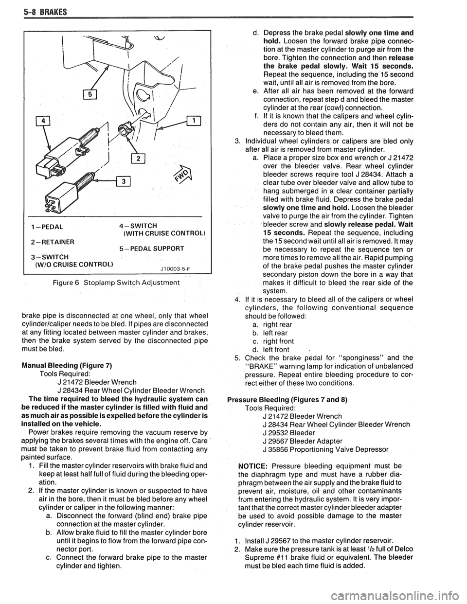
5-8 BRAKES
1 -PEDAL 4-SWITCH
(WITH CRUISE CONTROL)
2- RETAINER
5-PEDAL SUPPORT
3-SWITCH
I lWlO CRUISE CONTROLl J10003-5-F
Figure 6 Stoplamp Switch Adjustment
brake pipe is disconnected at one wheel, only that wheel
cylinderlcaliper needs to be bled. If pipes are disconnected
at any fitting located between master cylinder and brakes,
then the brake system served by the disconnected pipe
must be bled.
Manual Bleeding (Figure
7)
Tools Required:
J 21472 Bleeder Wrench
J 28434 Rear Wheel Cylinder Bleeder Wrench
The time required to bleed the hydraulic system can
be reduced if the master cylinder is filled with fluid and
as much air as possible is expelled before the cylinder is
installed on the vehicle.
Power brakes require removing the vacuum reserve by
applying the brakes several times with the engine off. Care
must be taken to prevent brake fluid from contacting any
painted surface.
1. Fill the master cylinder reservoirs with brake fluid and
keep at least half full of fluid during the bleeding oper-
ation.
2.
If the master cylinder is known or suspected to have
air in the bore, then it must be bled before any wheel
cylinder or caliper in the following manner:
a. Disconnect the forward (blind end) brake pipe
connection at the master cylinder.
b. Allow brake fluid to fill the master cylinder bore
until it begins to flow from the forward pipe con-
nector port.
c. Connect the forward brake pipe to the master
cylinder and tighten. d.
Depress the brake pedal slowly one time and
hold. Loosen the forward brake pipe connec-
tion at the master cylinder to purge air from the
bore. Tighten the connection and then release
the brake pedal slowly. Wait
15 seconds.
Repeat the sequence, including the
15 second
wait, until all air is removed from the bore.
e. After all air has been removed at the forward
connection, repeat step d and bleed the master
cylinder at the rear (cowl) connection.
f. If it is known that the calipers and wheel cylin-
ders do not
coiitain any air, then it will not be
necessary to bleed them.
Individual wheel cylinders or calipers are bled only
after all air is removed from master cylinder.
a. Place a proper size box end wrench or
J 21 472
over the bleeder valve. Rear wheel cylinder
bleeder screws require tool
J 28434. Attach a
clear tube over bleeder valve and allow tube to
hang submerged in a clear container partially
filled with brake fluid. Depress the brake pedal
slowly one time and hold. Loosen the bleeder
valve to purge the air from the cylinder. Tighten
bleeder screw and slowly release pedal. Wait
15 seconds. Repeat the sequence, including
the 15 second wait until all air is removed. It may
be necessary to repeat the sequence ten or
more times to remove all the air. Rapid pumping
of the brake pedal pushes the master cylinder
secondary piston down the bore in a way that
makes it difficult to bleed the rear side of the
system.
If it is necessary to bleed all of the calipers or wheel
cylinders, the following conventional sequence
should be followed: a. right rear
b. left rear
c. right front
d. left front
Check the brake pedal for "sponginess" and the
"BRAKE" warning lamp for indication of unbalanced
pressure. Repeat entire bleeding procedure to cor-
rect either of these two conditions.
Pressure Bleeding (Figures
7 and 8)
Tools Required:
J 21472 Bleeder Wrench
J 28434 Rear Wheel Cylinder Bleeder Wrench
J 29532 Bleeder
J 29567 Bleeder Adapter
J 35856 Proportioning Valve Depressor
NOTICE: Pressure bleeding equipment must be
the diaphragm type and must have a rubber dia-
phragm between the air supply and the brake fluid to
prevent air, moisture, oil and other contaminants
fram entering the hydraulic system. It is very impor-
tant that the correct master cylinder bleeder adapter
be used to avoid possible damage to the master
cylinder reservoir.
1. Install J 29567 to the master cylinder reservoir.
2. Make sure the pressure tank is at least
lh full of Delco
Supreme $1 1 brake fluid or equivalent. The bleeder
must be bled each time fluid is added.
Page 302 of 1825
BRAKES 5-9
TUBE hlUST BE
SUBMERGED IN
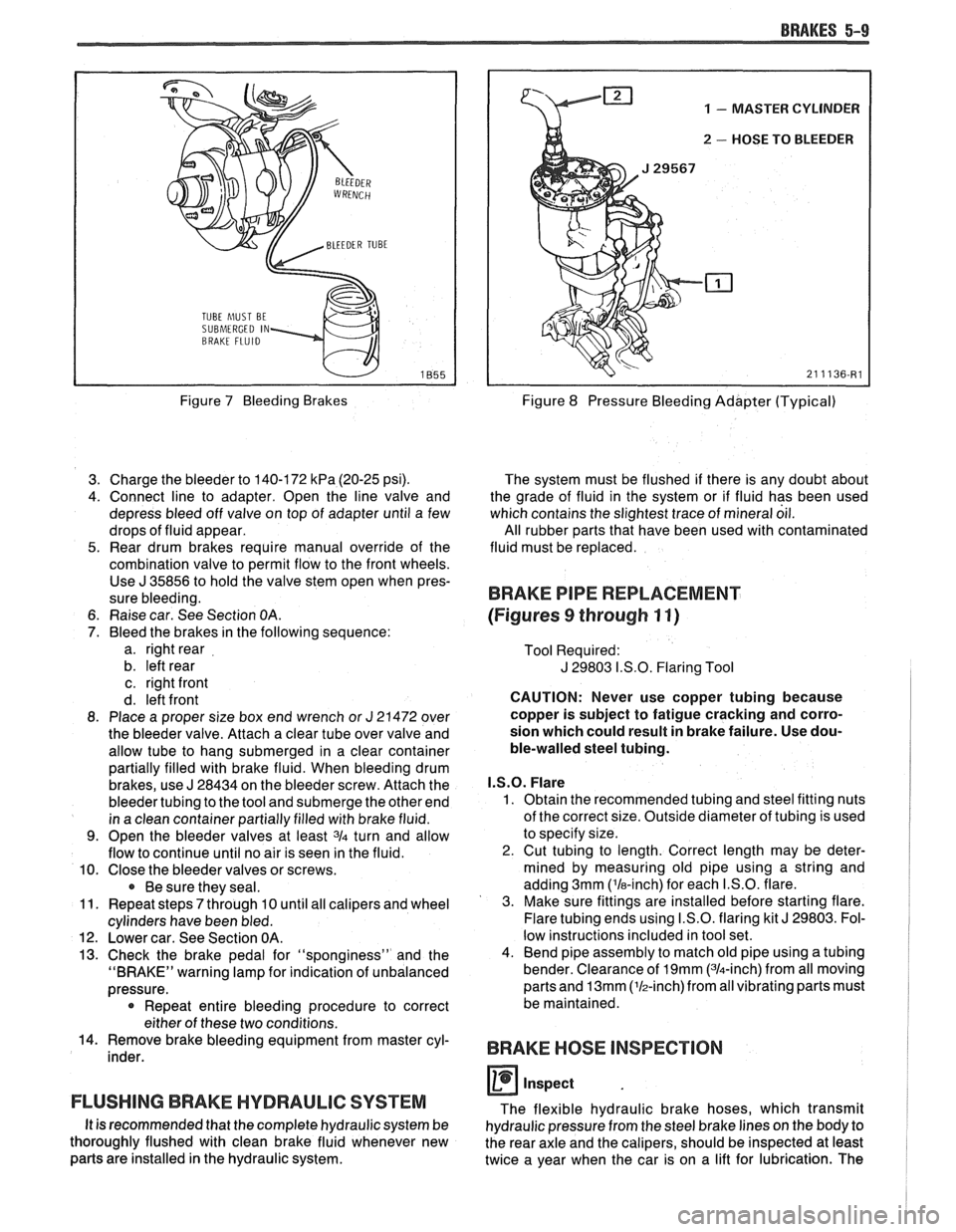
Figure 7 Bleeding Brakes
3. Charge the bleeder to 140-172
kPa (20-25 psi).
4. Connect line to adapter. Open the line valve and
depress bleed off valve on top of adapter until a few
drops of fluid appear.
5. Rear drum brakes require manual override of the
combination valve to permit flow to the front wheels. Use
J 35856 to hold the valve stem open when pres-
sure bleeding.
6. Raise car. See Section
OA.
7. Bleed the brakes in the following sequence:
a. right rear
b. left rear
c. right front
d. left front
8. Place a proper size box end wrench or
J 21472 over
the bleeder valve. Attach a clear tube over valve and
allow tube to hang submerged in a clear container
partially filled with brake fluid. When bleeding drum
brakes, use
J 28434 on the bleeder screw. Attach the
bleeder tubing to the tool and submerge the other end
in a clean container partially filled with brake fluid.
9. Open the bleeder valves at least 3/4 turn and allow
flow to continue until no air is seen in the fluid.
10. Close the bleeder valves or screws.
Be sure they seal.
11. Repeat steps
7 through 10 until all calipers and wheel
cylinders have been bled.
12. Lower car. See Section OA.
13. Check the brake pedal for "sponginess" and the
"BRAKE" warning lamp for indication of unbalanced
pressure.
* Repeat entire bleeding procedure to correct
either of these two conditions.
14. Remove brake bleeding equipment from master cyl-
inder.
FLUSHING BRAKE HYDRAULIC SYSTEM
It is recommended that the complete hydraulic system be
thoroughly flushed with clean brake fluid whenever new
parts are installed in the hydraulic system.
1 - MASTER CYLINDER
u 2 - HOSE TO BLEEDER
Figure 8 Pressure Bleeding Adapter (Typical)
The system must be flushed if there is any doubt about
the grade of fluid in the system or if fluid has been used
which contains the slightest trace of mineral oil.
All rubber parts that have been used with contaminated
fluid must be replaced.
BRAKE PIPE REPLACEMENT
(Figures
9 through 11)
Tool Required:
J 29803 I.S.O. Flaring Tool
CAUTION: Never use copper tubing because
copper is subject to fatigue cracking and corro-
sion which could result in brake failure. Use dou-
ble-walled steel tubing.
I.S.O. Flare
1. Obtain the recommended tubing and steel fitting nuts
of the correct size. Outside diameter of tubing is used
to specify size.
2. Cut tubing to length. Correct length may be deter-
mined by measuring old pipe using a string and
adding 3mm ('la-inch) for each I.S.O. flare.
3. Make sure fittings are installed before starting flare.
Flare tubing ends using I.S.O. flaring kit
J 29803. Fol-
low instructions included in tool set.
4. Bend pipe assembly to match old pipe using a tubing
bender. Clearance of
19mm (314-inch) from all moving
parts and
13mm (lh-inch)from all vibrating parts must
be maintained.
BRAKE HOSE INSPECTION
0 inspect
The flexible hydraulic brake hoses, which transmit
hydraulic pressure from the steel brake lines on the body to
the rear axle and the calipers, should be inspected at least
twice a year when the car is on a lift for lubrication. The
Page 313 of 1825
5A3-2 COMPOSlf E MASTER CYLINDER
GENERAL DESCRIPTION
This master cylinder is a composite design
(plastic reservoir and aluminum bore) incorporating
a
conventional front to rear brake system split. The
primary piston provides the fluid pressure to the front
brakes, while the secondary piston provides the fluid
pressure to the rear brakes. If pressure is lost from
either system, the remaining system will function to
stop the vehicle.
A quick take-up feature is incorporated which
provides a large volume of fluid to the wheel brakes at
low pressure with initial brake apply. The low pressure
fluid quickly provides the displacement requirements
created by the seal retraction of the pistons into the
front calipers.
Important
e Replace all components included in repair kits
used to service this master cylinder.
e Lubricate rubber parts with clean brake fluid to
ease assembly.
a Do not use lubricated shop air on brake parts as
damage to rubber components may result.
e If any hydraulic component is removed or
disconnected, it may be necessary to bleed all or
part of the brake system.
e The torque values specified are for dry,
unlubricated fasteners.
a Perform service operations on a clean bench free
from all mineral oil materials.
ON-CAR SERVICE
MASTER CYLINDER ASSEMBLY
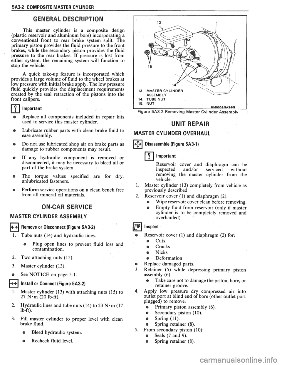
Remove or Disconnect (Figure 5,432)
1.
Tube nuts (14) and hydraulic lines.
e Plug open lines to prevent fluid loss and
contamination.
2. Two attaching nuts (15).
3. Master cylinder (13).
s See NOTICE on page 5-1.
Install or Connect (Figure 5A3-2)
1.
Master cylinder (13) with attaching nuts (15) to
27
N-m (20 lb-ft).
2. Hydraulic lines and tube nuts
(14) to 23 7%-m (17
lb-ft).
3. Fill master cylinder to proper level with clean
brake fluid.
e Bleed hydraulic system.
13. MASTER CYLINDER I ASSEMBLY
Figure 5A3-2 Removing Master Cylinder Assembly
MASTER CYLINDER OVERHAUL
+++ Disassemble (Figure 5A3-1) [I]
Important
Reservoir cover and diaphragm can be
inspected and/or serviced without
removing the master cylinder from the
vehicle.
1. Master cylinder (13) completely from vehicle as
previously described.
2. Reservoir cover (1) and diaphragm (2).
e Wipe reservoir cover clean before removing.
e Empty fluid from reservoir (only if master
cylinder is to be completely removed and
overhauled).
Inspect
s Reservoir cover (I) and diaphragm (2) for:
s Cuts
o Cracks
e Nicks
e Deformation
e Replace damaged parts.
3. Retainer
(5) while depressing primary piston
assembly (6).
e Take care not to damage the piston, bore, or
retainer groove.
4. Apply low pressure dry compressed air into
outlet port at blind end of bore (other outlet port
plugged) to remove:
@ Primary piston assembly (6).
s Secondary piston (10).
s Spring (1 1).
e Spring retainer (8).
5. From secondary piston (10):
e Seals (7 and 9).
Recheck fluid level. e Spring retainer (8).
Page 323 of 1825
586.2 DISC BRAKE CALIPER ASSEMBLY
GENERAL DESCRIPUON
This caliper has a single bore and is mounted to
the support bracket with two mounting bolts.
Hydraulic pressure, created by applying force to the
brake pedal, is converted by the caliper to a stopping
force. This force acts equally against the piston and the
bottom of the caliper bore to move the piston outward
and to move (slide) the caliper inward resulting in a
clamping action on the rotor. This clamping action
forces the linings against the rotor, creating friction to
stop the vehicle.
When the parking brake is applied, the lever turns
the actuator screw which is threaded into a nut in the
piston assembly. This causes the piston to move
outward and the caliper to slide inward mechanically,
forcing the linings against the rotor. The piston
assembly contains a self-adjusting mechanism to keep
the parking brake in proper adjustment.
NOTICE: Replace all components included in
repair kits used to service this caliper. Lubricate
rubber parts with clean brake fluid to ease
assembly. Do not
uhe lubricated shop air on brake
parts as damage to rubber components may result.
If any hydraulic
coniponent is removed or
disconnected,
it may he necessary to bleed all or
part of the brake system. Replace shoe and linings
in axle sets only. The torque values specified are
for dry,
unlubricated fasteners. Perform service
operations
011 a clean bench free from all mineral
oil materials.
ON-CAR SERVICE
CALIPER ASSEMBLY
Figures 2 thru 4
Remove or Disconnect
1. 2/3 of brake fluid from master cylinder assembly.
2. Raise car and suitably support.
e Mark relationship of wheel at axle flange.
3. Wheel and tire.
e Reinstall two lug liuts to retain rotor.
4. Loosen tension on parking brake cable at
equalizer.
5. Cable (29), return spring (3) and damper (37)
from return spring (3) (Figure 2).
6. Lock nut (1) while holding lever (2) (Figure 1).
7. Lever (2), lever seal (22), and anti-friction washer
(21) (Figure 1).
Inspect
e Lever, lever seal, and anti-friction washer
for:
-- Cuts
-- Nicks
-- Excessive wear
e Replace part(s) if any of the above are
found.
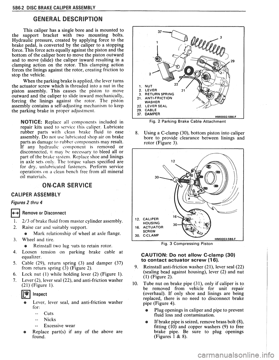
29
RETURN SPRING ANTI-FRICTION WASHER LEVER SEAL 1 29. CABLE I
Fig. 2 Parking Brake Cable Attachment
8. Using a C-clamp (30), bottom piston into caliper
bore to provide clearance between linings and
rotor (Figure 3).
30
CALIPER HOUSING ACTUATOR SCREW C-C LAMP
Fig. 3 Compressing Piston
CAUTION: Do not allow C-clamp (30)
to contact actuator screw (1 6).
9. Reinstall anti-friction washer (21), lever seal (22)
(sealing bead against housing), lever (2) and nut
(1) (Figure 2).
10. Tube nut on brake pipe
(31), only if caliper is to
be removed from vehicle for unit repair
(overhaul). If only shoe and linings are being
replaced, there is no need to disconnect brake
pipe (Figure
4).
Plug openings in caliper and pipe to prevent
fluid loss and contamination.
If brake pipe is seized, remove brass bolt
(8),
fitting (10) and copper washers (9) to free
brake pipe. Be sure to plug openings
(Figures 1
& 8).
Page 348 of 1825
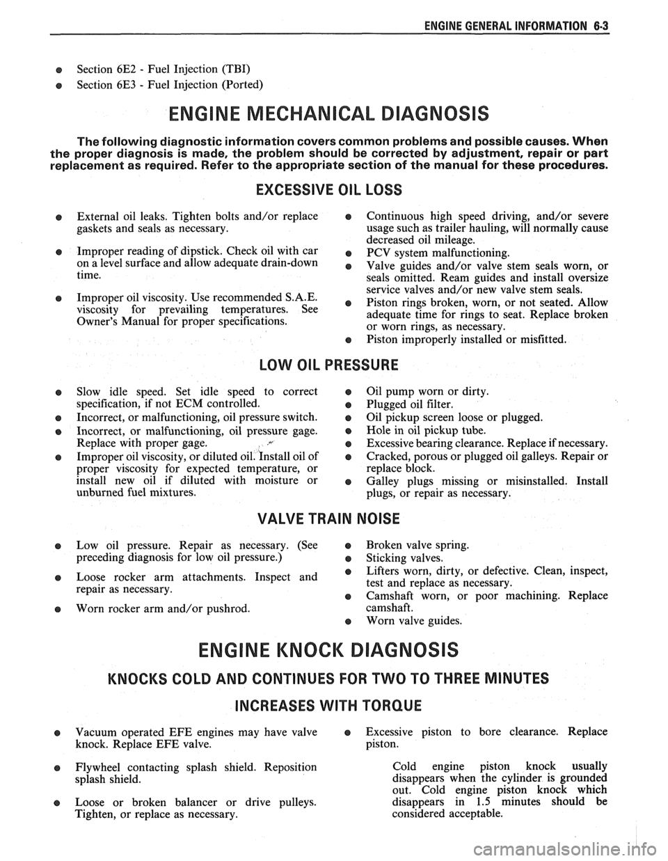
ENGINE GENERAL INFORMATION 6-3
B, Section 6E2 - Fuel Injection (TBI)
B, Section 6E3 - Fuel Injection (Ported)
ENGINE MECHANICAL DIAGNOSIS
The following diagnostic information covers common problems and possible causes. When
the proper diagnosis is made, the problem should be corrected by adjustment, repair or part
replacement as required. Refer to the appropriate section of the manual for these procedures.
EXCESSIVE OIL LOSS
B, External oil leaks. Tighten bolts and/or replace o Continuous high speed driving, and/or severe
gaskets and seals as necessary. usage
such as trailer hauling, will normally cause
decreased oil mileage.
e Improper reading of dipstick. Check oil with car PCV system malfunctioning. on a level surface and allow adequate drain-down Valve guides and/or valve stem seals worn, or time.
seals omitted. Ream guides and install oversize
service valves and/or new valve stem seals.
Improper Use S.A'E' Piston rings broken, worn, or not seateded. Allow viscosity for prevailing temperatures. See
adequate time for rings to seat. Replace broken
Owner's Manual for proper specifications.
or worn rings, as necessary.
Piston improperly installed or misfitted.
LOW OIL PRESSURE
Slow idle speed. Set idle speed to correct
specification, if not ECM controlled.
Incorrect, or malfunctioning, oil pressure switch.
Incorrect, or malfunctioning, oil pressure gage.
Replace with proper gage.
.*
Improper oil viscosity, or diluted oil. install oil of
proper viscosity for expected temperature, or
install new oil if diluted with moisture or
unburned fuel mixtures.
o Oil pump worn or dirty.
e Plugged oil filter.
e Oil pickup screen loose or plugged.
B, Hole in oil pickup tube.
e Excessive bearing clearance. Replace if necessary.
o Cracked, porous or plugged oil galleys. Repair or
replace block.
o Galley plugs missing or misinstalled. Install
plugs, or repair as necessary.
VALVE TRAIN NOISE
e Low oil pressure. Repair as necessary. (See o Broken valve spring.
preceding diagnosis for low oil pressure.)
o Sticking valves.
o Loose rocker arm attachments. Inspect and B, Lifters worn, dirty, or defective. Clean, inspect,
test and replace as necessary.
repair as necessary.
o Camshaft worn, or poor machining. Replace
o Worn rocker arm and/or pushrod. camshaft.
B, Worn valve guides.
ENGINE KNOCK DIAGNOSIS
KNOCKS COLD AND CONTINUES FOR TWO TO THREE MINUTES
INCREASES
WITH TORQUE
o Vacuum operated EFE engines may have valve o Excessive piston to bore clearance. Replace
knock. Replace EFE valve. piston.
e Flywheel contacting splash shield. Reposition
splash shield.
e Loose or broken balancer or drive pulleys.
Tighten, or replace as necessary. Cold engine piston knock usually
disappears when the cylinder is grounded
out. Cold engine piston knock which
disappears in 1.5 minutes should be
considered acceptable.
Page 350 of 1825
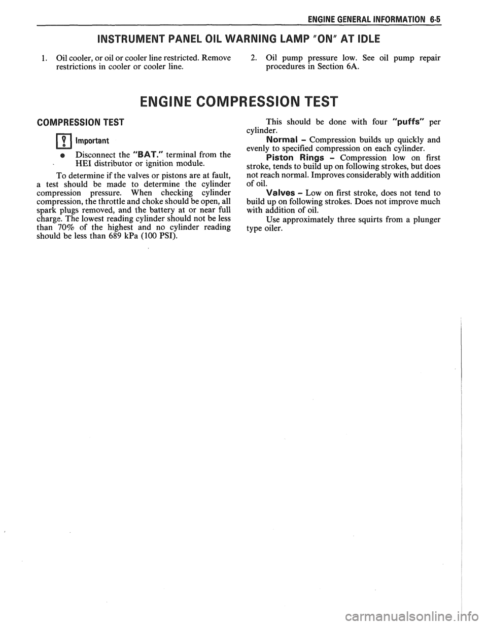
ENGINE GENERAL INFORMATION 6-5
INSTRUMENT PANEL OIL WARNING LAMP "ON" AT IDLE
1. Oil cooler, or oil or cooler line restricted. Remove 2. Oil pump pressure low. See oil pump repair
restrictions in cooler or cooler line. procedures
in Section
6A.
ENGINE COMPRESSION EST
COMPRESSION TEST
Important
e Disconnect the "BAT." terminal from the - HE1 distributor or ignition module.
To determine if the valves or pistons are at fault,
a test should be made to determine the cylinder
compression pressure. When checking cylinder
compression, the throttle and choke should be open, all
spark plugs removed, and the battery at or near full
charge. The lowest reading cylinder should not be less
than
70% of the highest and no cylinder reading
should be less than
689 kPa (100 PSI). This
should be done with four
"puffs" per
cylinder.
Normal - Compression builds up quickly and
evenly to specified compression on each cylinder.
Piston Rings - Compression low on first
stroke, tends to build up on following strokes, but does
not reach normal. Improves considerably with addition
of oil.
Valves - Low on first stroke, does not tend to
build up on following strokes. Does not improve much
with addition of oil.
Use approximately three squirts from a plunger
type oiler.