tire type PONTIAC FIERO 1988 Service User Guide
[x] Cancel search | Manufacturer: PONTIAC, Model Year: 1988, Model line: FIERO, Model: PONTIAC FIERO 1988Pages: 1825, PDF Size: 99.44 MB
Page 233 of 1825
3E.2 TIRES AND WHEELS
P-METRIC SIZED TIRES
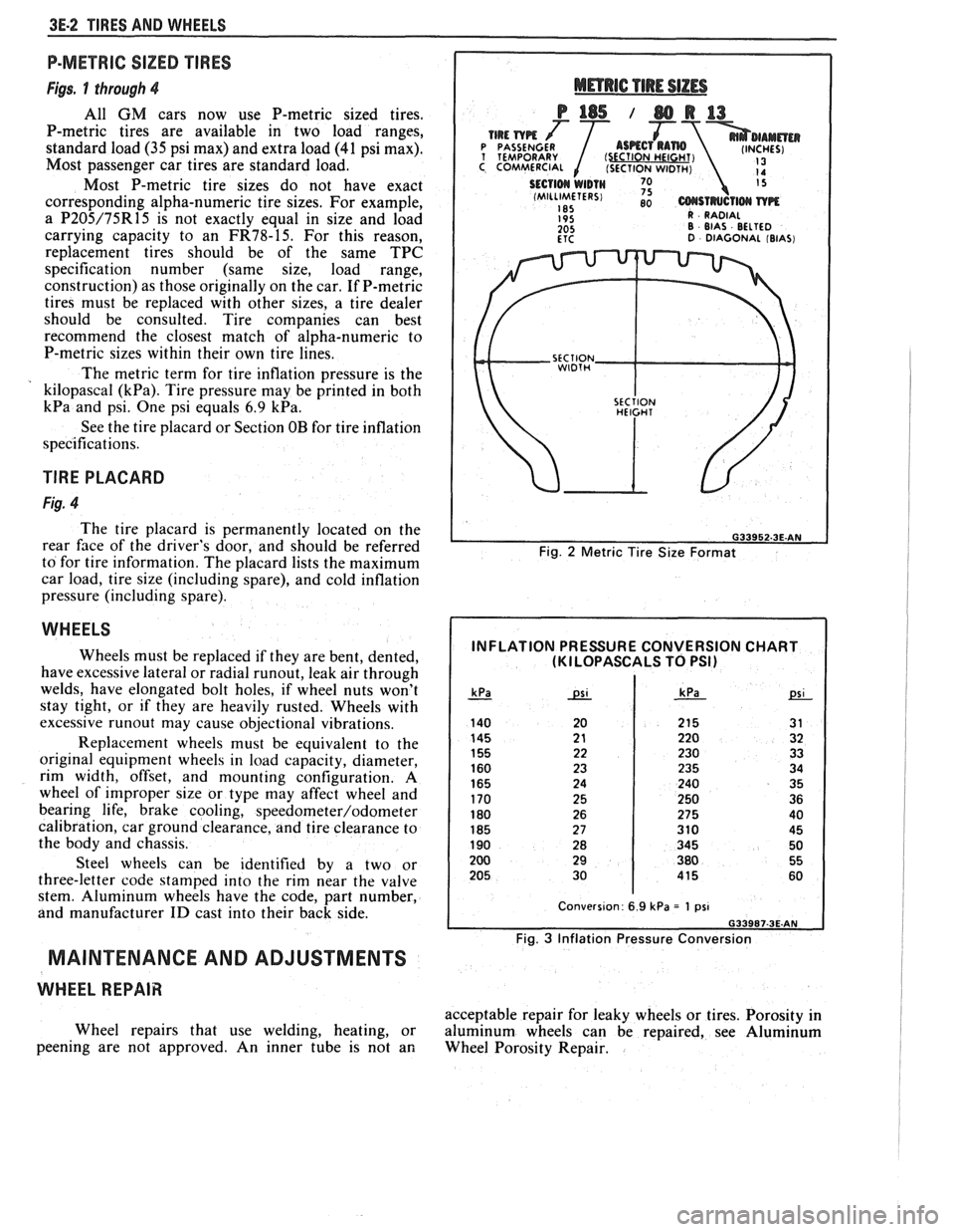
Figs. 1 through 4
All GM cars now use P-metric sized tires.
P-metric tires are available in two load ranges,
standard load
(35 psi max) and extra load (41 psi max).
Most passenger car tires are standard load.
Most P-metric tire sizes do not have exact
corresponding alpha-numeric tire sizes. For example,
a
P205/75R15 is not exactly equal in size and load
carrying capacity to an
FR78-15. For this reason,
replacement tires should be of the same TPC
specification number (same size, load range,
construction) as those originally on the car. If P-metric
tires must be replaced with other sizes, a tire dealer
should be consulted. Tire companies can best
recommend the closest match of alpha-numeric to
P-metric sizes within their own tire lines.
The metric term for tire inflation pressure is the
kilopascal
(kPa). Tire pressure may be printed in both
kPa and psi. One psi equals 6.9 kPa.
See the tire placard or Section OB for tire inflation
specifications.
TlRE PLACARD
Fig. 4
The tire placard is permanently located on the
rear
face of the driver's door, and should be referred
to for tire information. The placard lists the maximum
car load, tire size (including spare), and cold inflation
pressure (including spare).
WHEELS
Wheels must be replaced if they are bent, dented,
have excessive lateral or radial
runout, leak air through
welds, have elongated bolt holes, if wheel nuts won't
stay tight, or if they are heavily rusted. Wheels with
excessive
runout may cause objectional vibrations.
Replacement wheels must be equivalent to the
original equipment wheels in load capacity, diameter,
rim width, offset, and mounting configuration.
A
wheel of improper size or type may affect wheel and
bearing life, brake cooling,
speedometer/odometer
calibration, car ground clearance, and tire clearance to
the body and chassis.
Steel wheels can be identified by a two or
three-letter code stamped into the rim near the valve
stem. Aluminum wheels have the code, part number,
and manufacturer
ID cast into their back side.
MAINTENANCE AND ADJUSTMENTS
WHEEL REPAIR
Wheel repairs that use welding, heating, or
peening are not approved. An inner tube is not an
Fig. 2 Metric Tire Size Format
INFLATION PRESSURE CONVERSION CHART (KI LOPASCALS TO PSI)
Fig. 3 Inflation Pressure Conversion
acceptable repair for leaky wheels or tires. Porosity in
aluminum wheels can be repaired, see Aluminum
Wheel Porosity Repair.
Page 235 of 1825
3E.4 TIRES AND WHEELS
TIRE CHAIN USAGE
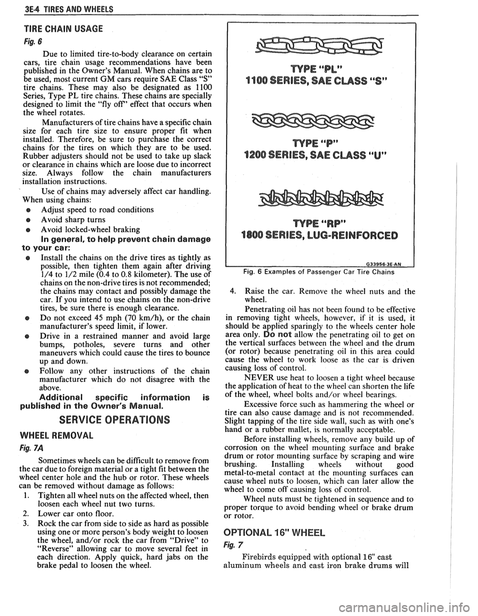
Fig. 6
Due to limited tire-to-body clearance on certain
cars, tire chain usage recommendations have been
published in the Owner's Manual. When chains are to
be used, most current
GM cars require SAE Class "S"
tire chains. These may also be designated as 1100
Series, Type PL tire chains. These chains are specially
designed to limit the "fly off' effect that occurs when
the wheel rotates.
Manufacturers of tire chains have a specific chain
size for each tire size to ensure proper fit when
installed. Therefore, be sure to purchase the correct
chains for the tires on which they are to be used.
Rubber adjusters should not be used to take up slack
or clearance in chains which are loose due to incorrect
size. Always follow the chain manufacturers
installation instructions.
Use of chains may adversely affect car handling.
When using chains:
@ Adjust speed to road conditions
@ Avoid sharp turns
@ Avoid locked-wheel braking
In general, to help prevent chain damage
to your car:
@ Install the chains on the drive tires as tightly as
possible, then tighten them again after driving
1/4 to 1/2 mile (0.4 to
0.8 kilometer). The use of
chains on the non-drive tires is not recommended;
the chains may contact and possibly damage the
car. If you intend to use chains on the non-drive
tires, be sure there is enough clearance.
e Do not exceed 45 mph (70 km/h), or the chain
manufacturer's speed limit, if lower.
@ Drive in a restrained manner and avoid large
bumps, potholes, severe turns and other
maneuvers which could cause the tires to bounce
up and down.
e Follow any other instructions of the chain
manufacturer which do not disagree with the
above.
Additional specific information is
published in the Owner's Manual.
SERVICE OPERATIONS
WHEEL REMOVAL
Fig. 7A
Sometimes wheels can be difficult to remove from
the car due to foreign material or a tight fit between the
wheel center hole and the hub or rotor. These wheels
can be removed without damage as follows:
1. Tighten all wheel nuts on the affected wheel, then
loosen each wheel nut two turns.
2. Lower car onto floor.
3. Rock the car from side to side as hard as possible
using one or more person's body weight to loosen
the wheel, and/or rock the car from
"Drive" to
"Reverse" allowing car to move several feet in
each direction. Apply quick, hard jabs on the
brake pedal to loosen the wheel.
WPE ""P"
1200 SERIES, SAE CUSS ""Up
WPE ""RP"
4800 SERIES, LUG-REINFORCED
Fig. 6 Examples of Passenger Car Tire Chains
4.
Raise the car. Remove the wheel nuts and the
wheel.
Penetrating oil has not been found to be effective
in removing tight wheels, however,
if it is used, it
should be applied sparingly to the wheels center hole
area only.
DO not allow the penetrating oil to get on
the vertical surfaces between the wheel and the drum
(or rotor) because penetrating oil in this area could
cause the wheel to work loose as the car is driven
causing loss of control.
NEVER use heat to loosen a tight wheel because
the application of heat to the wheel can shorten the life
of the wheel, wheel bolts and/or wheel bearings.
Excessive force such as hammering the wheel or
tire can also cause damage and is not recommended.
Slight tapping of the tire side wall, such as with one's
hand or a rubber mallet, is normally acceptable.
Before installing wheels, remove any build up of
corrosion on the wheel mounting surface and brake
drum or rotor mounting surface by scraping and wire
brushing. Installing wheels without good
metal-to-metal contact at the mounting surfaces can
cause wheel nuts to loosen, which can later allow the
wheel to come off causing loss of control.
Wheel nuts must be tightened in sequence and to
proper torque to avoid bending wheel or brake drum
or rotor.
0P"FIONAL 16" WHEEL
Fig. 7
Firebirds equipped with optional 16" cast
aluminum wheels and cast iron brake
drums will
Page 238 of 1825
TIRES AND WHEELS 3E-7
STMAWAY SPARE
TEMPORARY USE ONLV
Fig. 11 Stowaway Spare
MATCH MOUNTING
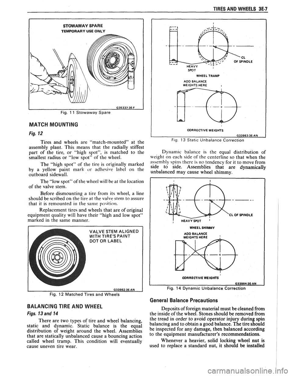
Fig. 12
Tires and wheels are "match-mounted" at the
assembly plant. This means that the radially stiffest
part of the tire, or "high spot", is matched to the
smallest radius or "low spot" of the wheel.
The "high spot" of the tire is originally marked
by a yellow paint mark
or adhesive label on the
outboard sidewall.
The "low spot" of the wheel will be at the location
of the valve stem.
Before dismounting
a tire from its wheel, a line
should be scribed on the tire at the valve
stem to assure
that it is remounted
ill the same poqition.
Replacement tireq and wheels that are of original
equipment quality will have their "high and low spot"
marked in the same manner.
DOT OR LABEL
SPOT I WHEEL TRAMP I
ADD BALANCE WEIGHTS HERE I
I CORRECTIVE WEIGtiYS I
L G33963-3E.AN Fig 13 Stat~c Unbalance Correction
Dynam~c balance 1s the equal distribution of
weight on each side of the centerline so that when the
n\\embly spin there 14 no tendency for it to move from
side to side. Assemblies that are dynamically
unbalanced may cause wheel shimmy.
WHEEL SHlWWUV
ADDBALANCE , WEtGHTS HERE
Fig. 14 Dynamic Unbalance Correction
Fig.
12 Matched Tires and Wheels
General Balance Precautions
BALANCING TIRE AND WHEEL
Figs, 13 and 14
There are two types of tire and wheel balancing,
static and dynamic. Static balance is the equal
distribution of weight around the wheel. Assemblies
that are statically unbalanced cause a bouncing action
called wheel tramp. This condition will eventually
cause uneven tire wear. Deposits
of foreign material must be cleaned from
the inside of the wheel. Stones should be removed from
the tread in order to avoid operator injury during spin
balancing and to obtain a good balance. The tire should
be inspected for any damage, then balanced according
to the equipment manufacturer's recommendations.
Whenever a heavier, solid locking wheel nut is
used to replace a standard nut, it should
be installed
Page 239 of 1825
3E-8 TIRES AND WHEELS
nearest the valve stem, and a 1/2 ounce balance weight
should be added 180" opposite the locking nut on the
wheel's inboard side.
When rotating tires, always re-install the locking
nut nearest the tire valve stem so that it remains
opposite the 1/2 ounce balance weight. This procedure
will improve the on-car wheel balance by compensating
for the heavy locking wheel nut.
Off-Car Balancing
Most electronic off-car balancers are more
accurate than the on-car spin balancers. They are easy
to use and give a dynamic (two plane) balance.
Although they do not correct for drum or rotor
unbalance as does on-car spin balancing, this is
overcome by their accuracy (usually to within 1/8
ounce). When balancing off-car, the wheel should
locate on the balancer with a cone through the back
side of the center pilot hole (not by the wheel stud
holes).
On-Car Balancing
When needed, on-car balancing will help correct
vibrations due to brake drum, rotor, and wheel cover
imbalance.
When balancing on car, do not remove the
balance weights from the off-car dynamic balance. If
more than one ounce of additional weight is required,
it should be split between the inner and outer rim
flange.
NOTICE: The driven tire and wheel assemblies
should be spun using the engine. Limit speed as
stated in the following Caution.
CAUTION: Do not spin the drive
wheels faster than
35 mph (55 km/h)
as indicated by the speedometer. This
limit is necessary because the
speedometer indicates only one-half
of the actual wheel speed when one
drive wheel is spinning and the other
drive wheel is stopped. Personal injury
and damage may result from high
speed spinning.
CAUTION: On cars equipped with
limited slip rear axles, do not attempt
to balance a tire on a
drive wheel with
the other drive wheel on the ground.
The car may drive through this wheel
and cause the car to move
unexpectedly, resulting in personal
injury and property damage.
To distinguish between standard rear axle and
limited slip, raise rear of car so both tires are clear of
ground. With the transmission in park (in gear with
manual transmission), attempt to turn one wheel by
hand. If the wheel can be turned, it is a standard rear
axle; if the wheel cannot be turned, it is a limited slip
rear axle. Also, check for Limited Slip
(G80) on Service
Parts Identification label.
Wheel Weights
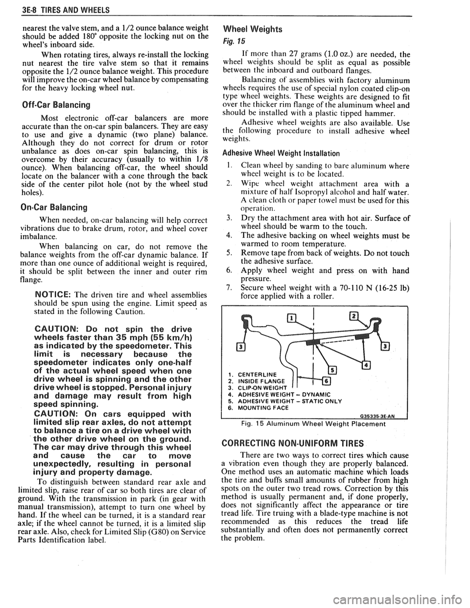
Fig. 15
If more than 27 grams (1.0 oz.) are needed, the
wheel weights should be split as equal as possible
between the inboard and outboard flanges.
Balancing of' assemblies with factory aluminum
wheels requires the use of special nylon coated clip-on
type wheel weights. These weights are designed to fit
over the thicker rim flange of the aluminum wheel and
should be installed with a plastic tipped hammer.
Adhesive wheel weights are also available. Use
the following procedure to install adhesive wheel
weights.
Adhesive Wheel Weight Installation
1. Clean wheel by sanding to bare aluminum where
wheel weight is to be located.
2. Wipe wheel weight attachment area with a
mixture of half Isopropyl alcohol and half water.
A clean cloth or paper towel niust be used for this
operat ion.
3. Dry the attachment area with hot air. Surface of
wheel should be warm to the touch.
4. The adhesive backing on wheel weights must be
warmed to room temperature.
5. Remove tape from back of weights. Do not touch
the adhesive surface.
6. Apply wheel weight and press on with hand
pressure.
7. Secure wheel weight with a 70-1 10
N (16-25 lb)
force applied with a roller.
CENTERLINE
1 INSIDE FLANGE CLIPBN WEIGHT 4. ADHESIVE WEIGHT - DYNAMIC 5. ADHESIVE WEIGHT -STATIC ONLY 6. MOUNTING FACE
Fig. 15 Aluminum Wheel Weight Placement
CORRECTING NON-UNIFORM TIRES
There are two ways to correct tires which cause
a vibration even though they are properly balanced.
One method uses an automatic machine which loads
the tire and buffs small amounts of rubber from high
spots on the outer two tread rows. Correction by this
method is usually permanent and, if done properly,
does not significantly affect the appearance or tire
tread life. Tire truing with a blade-type
machine is not
recommended as this reduces the tread life
substantially and often does not permanently correct
the problem.
Page 242 of 1825
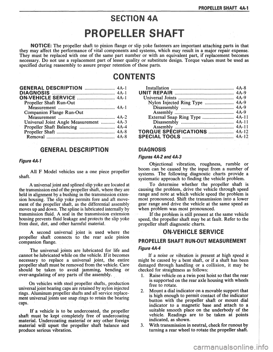
PROPELLER SHAFT 4A-1
PROPELLER SHAFT
NOTICE: The propeller shaft to pinion flange or slip yoke fasteners are important attaching parts in that
they may affect the performance of vital components and systems, which may result in a major repair expense.
They must be replaced with one of the same part number or with an equivalent part, if replacement becomes
necessary. Do not use a replacement part of lesser quality or substitute design. Torque values must be used as
specified during reassembly to assure proper retention of these parts.
CONTENTS
GENERAL DESCRIPTION ........................ 4A-1
DIAGNOSIS ......................... ............ 4A-1
ON-VEHICLE SERVICE ........................... 4A-I
Propeller Shaft Run-Out
....................................... Measurement 4A- 1
Companion Flange Run-Out
Measurement
............................................. 4A-2
........... Universal Joint Angle Measurement 4A-3
............................ Propeller Shaft Balancing 4A-4
.............................................. Propeller Shaft 4A-8
Removal
.................... .. ............................. 4A-8
GENERAL DESCRIPTION
Figure 4A- I
.............................................. Installation 4A-8
UNIT REPAIR ............................................... 4A-9
Universal Joints
...................... ... ............ 4A-9
....................... Nylon Injected Ring Type 4A-9
..... ....................... Disassembly .... 4A-9
.......................................... Assembly 4A-9
......................... External Snap Ring Type 4A- l 1
............. .................... Disassembly .. 4A- 1 1
........................................... Assembly
4A- 1 1
.................... TORQUE SPECIFICATIONS 4A-12
.................................. SPECIAL TOOLS 4A-12
DIAGNOSIS
Figures 4A-2 and 4A-3
Obiectional vibration, roughness, rumble or
boom
can be caused by the input from a number of
shaft. use a One piece propeller systems. The following diagnostic charts provide a
systematic approach to finding the vehicle problem.
A universal joint and splined slip yoke are located at
the transmission end of the propeller shaft, where they are
held in alignment by a bushing in the transmission exten-
sion housing. The slip yoke permits fore and aft move-
ment of the propeller shaft, as the differential assembly
moves up and down. The spline is lubricated internally by
transmission fluid. A seal in the transmission extension
housing prevents fluid leakage and protects the slip yoke
from dust,
dirt, and other harmful material.
A second universal joint is used where the
propeller shaft connects to the rear axle pinion
companion flange.
The universal joints are lubricated for life and
cannot be lubricated while on the vehicle.
If it becomes
necessary to replace a universal joint, the entire
propeller shaft must be removed from the vehicle. Care
should be taken to avoid jamming, bending or
over-angulating of any parts of the assembly.
On vehicles with steel propeller shafts, production
universal joint bearing caps are retained by nylon injected
rings. Aluminum propeller shafts and all service replace-
ment universal joints use snap rings to retain the bearing
caps.
If a vehicle is to be undercoated, the propeller
shaft must be kept completely free of undercoating
material. Undercoating material or any other foreign
material will upset the propeller shaft balance and
produce serious vibration. To
determine whether the propeller shaft is
causing the problem, drive the vehicle through speed
range and note at which vehicle speed the problem is
most pronounced. Shift the transmission into a lower
gear range and drive the vehicle at the same speed as
when problem was most pronounced.
If the problem is still present at the same vehicle
speed, the propeller shaft may be at fault. Refer to the
propeller shaft diagnostic charts.
ON-VEHICLE SERVICE
PROPELLER SHAFT RUN-OUT MEASUREMENT
Figure 4A-4
If a noise or vibration is present at high speed it
might be caused by a bent shaft, or if a shaft has been
damaged through handling or a collision, it may be
checked for straightness as follows:
1. Raise vehicle on a twin post hoist so that the rear
is supported on the rear axle housing with wheels
free to rotate.
2. Mount
a dial indicator on a movable support that
is high enough to permit contact of the indicator
button with the propeller shaft or mount dial
indicator to a magnetic base and attach to a
suitable smooth place on the underbody of the
vehicle. Readings are to be taken at points
indicated, as shown.
3. With transmission in neutral, check for runout by
turning a rear wheel to rotate the propeller shaft.
Page 252 of 1825
I
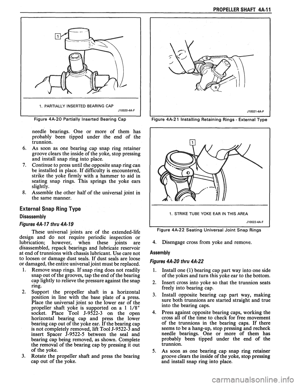
1. PARTIALLY INSERTED BEARING CAP J10020-4A-F I
Figure 4A-20 Partially Inserted eari in^ Cap
needle bearings. One or more of them has
probably been tipped under the end of the
trunnion.
6. As soon as one bearing cap snap ring retainer
groove clears the inside of the yoke, stop pressing
and install snap ring into place.
7. Continue to press until the opposite snap ring can
be installed in place. If difficulty is encountered,
strike the yoke firmly with a hammer to aid in
seating snap rings. This springs the yoke ears
slightly.
8. Assemble the other half of the universal joint in
the same manner.
External Snap Ring Type
Disassembly
Figures 4A- 17 thru 4A- 19
These universal joints are of the extended-life
design and do not require periodic inspection or
lubrication; however, when these joints are
disassembled, repack bearings and lubricate reservoir
at end of trunnions with chassis lubricant. Use care not
to loosen or damage dust seals. If dust seals are loose
or damaged, the entire universal joint must be replaced.
1. Remove snap rings. If snap ring does not readily
snap out of the grooves, tap the end of the bearing
cap lightly to relieve the pressure against the snap
ring.
2. Support the propeller shaft in a horizontal
position in line with the base plate of a press.
Place the universal joint so the lower ear of the
propeller shaft yoke is supported on a
1 1/8"
socket. Place Tool J-9522-3 on the open
horizontal bearing cap and press the lower
bearing cap out of the yoke ear. If the bearing cap
is not completely removed, lift Tool
9-9522-3 and
insert Spacer
J-9522-5 between the seal and
bearing cap being removed, as shown. Complete
the removal of the bearing cap by pressing it out
of the yoke.
3. Rotate the propeller shaft and press the bearing
cap out of the yoke.
PROPELLER SHAFT 4A-11
I I Figure 4A-2 1 Installing Retaining Rings - External Type
I 1. STRIKE TUBE YOKE EAR IN THIS AREA I
Figure 4A-22 Seating Universal Joint Snap Rings
4. Disengage cross from yoke and remove.
Assembly
Figures 4A-20 thru 4A.22
1. Install one (1) bearing cap part way into one side
of the yokes and turn this yoke ear to the bottom.
2. Insert cross into yoke so that the trunnion seats
freely into bearing cap.
3. Install opposite bearing cap part way, making
sure both trunnions are started straight and true
into the bearing caps.
4. Press against opposite bearing caps, working the
cross all of the time to check for free movement
of the trunnions in the bearing caps. If there
seems to be a hang-up, stop pressing and recheck
needle bearings. One or more of them has
probably been tipped under the end of the
trunnion.
5. As soon as one bearing cap snap ring retainer
groove clears the inside of the yoke, stop pressing
and install snap ring into place.
Page 254 of 1825
REAR AXLE 481-1
SECTION 4B4
BORG WARNER REAR AXLE
NOTICE: All rear axle attaching fasteners are an
necessary. Do not use a replacement part of lesser
important part in that they could affect the
quality or substitute design. Torque values must
performance of vital parts and systems, and/or
be used as specified during reassembly to assure
could result in major repair expense. They must
proper retention of all parts. (There is to be no
be replaced with one of the same part number or
welding as it may result in extensive damage and
with an equivalent part if replacement becomes
weakening of the metal.)
CONTENTS
General Description ............................... 4B 1- I
......... Standard Rear Axle ................... ..... 4B 1 - 1
General Information ............................. .... 4B 1- 1
Limited-Slip Rear Axle .............................. 4B 1-2
Operation
............................................ 4B 1-3
Diagnosis and Testing .......................... 4B 1-2
Axle Noises
..................... .... .................. 4B 1-2
Gear Noise
................................... .... .. 4B 1-4
Bearing Noise
......................... ...... ... 4B 1-4
Rear Wheel Bearing Noise ..................... 4B 1-4
Knock At Low Speeds
....................... ..... 4B 1-4
Backlash Clunk
................................... 4B 1-4
Diagnosis
................................................ 4B 1-4
Pre-Repair Investigation and Trouble
Diagnosis
....................... .. .................... 4B 1-4
...................................... On-Vehicle Sewice 4B 1-7
Carrier Cover and Gasket .......................... 4B 1-7
.............. Axle Shaft ......................... ....., 4B 1-7
Tooth Contact Pattern Test
................... 4B 1-8
Procedure
.................... .. ...................... 4B 1-8
Effects of Increasing Load on
Teeth Contact Pattern
......................... 4B 1-8
Adjustments Affecting Tooth
................................................ Contact 4B 1-8
Effects of Pinion
Postion on Tooth Pattern
............................................... 4B
1-8
Pinion Oil Seal and Companion
Flange Replacement
................... .. ...... 4B 1-8
Rear Wheel Bolt
........................................ 4B 1 - 10
Rear Axle Assembly
................................... 4B I - 10
Unit Repair
............................................... 4Bl-1 1
Drain Rear Axle Assembly ........................ 4B I - I I
Differential Assembly ............................. 4B 1 - 1 1
Hypoid Pinion & Pinion Bearings .......... 4B 1- I I
Four Pinion Standard Differential
Assembly
....................... ... ........... 4B 1 - 1 3
Inspection
............................................ 4B 1 - I:!
Differential Assembly .......................... 4B 1 - 14
Differential Bearing Preload Spacer
................... ...................... Selection .. 4B I - 11
.................................................. Pinion 4B 1 - 15
Operation of Limited Slip Rear Axle
........................................... (Cone Type) 4B 1 - 17
Checking Limited-Slip Function
............ 4B 1 - 17
......................... Limited Slip Differential 4B 1 - 18
.............. Disassembly Inspection Chart 4B
1- 18
......................... Limited Slip Differential 4B I - 1 X
............................................. Specifications
4B 1- 19
Axle Code Identification Chart
............ 4B 1-19
............................................. Special Tools 4B 1-20
GENERAL DESCRIPTION
STANDARD REAR AXLE All parts necessary to transmit power from the
propeller shaft to the rear wheels are enclosed in a
The rear axle assembly is of the semi-floating type salisbury type axle housing (a carrier casting with tubes
in which the car weight is carried on the axle housing.
pressed and welded into the carrier to form a complete The rear axle assembly is designed for use with an open carrier and tube assembly). A removable steel cover drive line and coil springs. The rear axle has a hypoid bolted to the rear of the carrier permits service of the type ring gear and pinion with the centerline of the rear axle without removing the entire assembly from
pinion gear below the centerline of the ring gear.
the car.
GENERAL INFORMATION
NOTICE: Most rear axle service repairs can be
Two pre-loaded tapered roller bearings support the
made with the rear axle assembly in the car, by
hypoid pinion gear in the carrier. The inner race of the
raising the rear end of the car with the rear axle
rear bearing is a tight press fit on the pinion stem. The
hanging on the shock absorbers.
inner race of the front bearing combines a light press
fit to a close sliding fit on the pinion flange end of the
A universal joint connects the rear end of the pinion stem. The outer race of each bearing is pressed
propeller shaft to a companion flange having a splined against a shoulder recessed in the carrier. Tightening
end which fits over and drives the
hypoid pinion gear. the pinion nut compresses a collapsible spacer which
Page 255 of 1825
4819 REAR AXLE
bears against the inner race of the front bearing and a
shoulder on the pinion stem. This spacer is used to
enable accurate bearing pre-load adjustment and
maintain a pre-load on both front and rear pinion
bearings, Adjustment of the fore and aft position of the
pinion is obtained by placing a shim between the rear
pinion bearing cup and axle housing. The differential
case is of two-piece construction and is supported in
the carrier by two tapered roller side bearings. Pre-load
rear axle case by inserting shims between the bearings
and the carrier. The rear axle case assembly is
positioned for proper ring gear to pinion backlash by
varying the shim thickness from side to side. The ring
gear is bolted to the case. Two side gears have splined
bores for driving the axle shafts. They are positioned
to turn in counterbored cavities in the case. The four
rear axle pinions have smooth bores and are held in
position by a pinion cross shaft, mounted and locked
in the rear axle case. All six gears are in mesh with each
other and because the pinion gears turn freely on their
shaft, they act as idler gears when the rear wheels are
turning at different speeds. The pinions and side gears
are backed by steel thrust washers.
LIMITED-SLIP REAR AXLE
The operation of the Limited-Slip differential is
the same as the standard differential, except that there
is additional friction provided by the conical clutches.
Under ordinary driving and cornering conditions, the
cones slip, allowing the outside wheel to turn faster
than the inner. Under poor traction conditions, such as
ice, snow, or loose gravel under one driving wheel, the
increased friction provided by the cones increases the
driving torque available to the wheel with the better
traction. The cones are spring loaded to provide the
increased driving torque under extremely low traction
conditions.
Operation
When the vehicle turns a corner, the outer rear
wheel must turn faster than the inner wheel. The inner
wheel, turning slower than the outer wheel, slows its
differential side gear (as the axle shaft is splined to the
side gear) and the differential pinion gears will roll
around the slowed differential side gear, driving the
other differential side gear and wheel faster.
DIAGNOSIS AND TESTING
Many noises reported as coming from the rear
axle assembly actually originate from other sources
such as tires, road surfaces, front wheel bearings, axle
bearing, engine, transmission, muffler or body
drumming. A thorough and careful check should be
made to determine the source of the noise before
disassembling the rear axle. Noise which originates in
other places cannot be corrected by adjustment or
replacement of parts in the differential. It should also
be remembered that rear axle gears, like any other
mechanical device, are not absolutely quiet and should
be accepted as being commercially quiet unless some
abnormal noise is present.
To make a systematic check for axle noise under
standard conditions, observe the following:
1. Select a level smooth asphalt road to reduce tire
noise and body drumming.
2. Check rear axle lubricant to assure correct level,
then drive car far enough to thoroughly warm up
rear axle lubricant, approximately 10 miles.
3. Note speed and RPM at which noise occurs. Stop
car and put transmission in neutral. Run engine
slowly up and down through engine speeds,
corresponding to car speed at which noise was
most pronounced, to determine if it is caused by
exhaust, muffler roar or other engine conditions.
4. Tire noise changes with different road surfaces,
but rear axle noise does not. Temporarily
inflating all tires to approximately 50 pounds
pressure
for test purposes only will materially
alter noise caused by tires, but will not affect noise
caused by rear axle. Rear axle noise usually stops
when coasting at speeds under 30 miles per hour;
however, tire noise continues, but with lower
tone, as car speed is reduced. Rear axle noise
usually changes when comparing acceleration
and coast, but tire noise remains about the same.
Distinguish between tire noise and rear axle noise
by noting if noise varies with various speeds or
sudden acceleration and deceleration; exhaust
and axle noise show variations under these
conditions while tire noise remains constant and
is more pronounced at speeds of 20 to 30 miles
per hour. Further check for tire noise by driving
car over smooth pavements or dirt roads (not
gravel) with tires at normal pressure. If noise is
caused by tires, it will noticeably change or
disappear and reappear with changes in road
surface.
5. Loose or rough front wheel bearings will cause
noise which may be confused with rear axle
noises; however, front wheel bearing noise does
not change when comparing drive and coast.
Light application of brakes while holding car
speed steady will often cause wheel bearing noise
to diminish, as this takes some weight off the
bearing. Front wheel bearings may be easily
checked for noise by jacking up the wheels and
spinning them, also by shaking wheels to
determine if bearings are loose.
6. Rear suspension rubber bushings and spring
insulators dampen out rear axle noise when
correctly installed. Check to see that no metallic
contact exists between the spring and spring seat
opening in frame or between upper and lower
control arm bushings and frame or axle housing
brackets. The track bar and torque arm must be
bolted securely. Metal-to-metal contact at those
points may result in telegraphing road noise and
normal axle noise which would not be
objectionable if dampened by bushings.
AXLE NOISES
After the noise has been determined as being in
the axle by following the above appraisal procedure,
the type of axle noise should be determined to aid in
making repairs if necessary.
Page 257 of 1825
481-4 REAR AXLE
Gear Noise
Gear noise (whine) is audible from 20 to 55 mph
under four driving conditions:
1. Light Acceleration - Accelerate slowly.
2. Road Load
- Car
driving load or constant speed.
3. Float - Using enough throttle to keep the car from
driving the engine
- car slows down gradually but
engine still pulls slightly.
4. Coast - Throttle closed and car in gear.
Bearing Noise
Bad bearings generally produce more of a rough
growl or grating sound, rather than the whine typical
of gear noise. Bearing noise frequently "wow-wows" at
bearing rpm, indicating a defective pinion or rear axle
case side bearing. This noise could easily be confused
with rear wheel bearing noise. Inspect and replace as
required.
Rear Wheel Bearing Noise
A rough rear wheel bearing produces a noise
which continues with car coasting at low speed and
transmission in neutral. Noise may diminish some by
gentle braking. With rear wheels jacked up, spin rear
wheels by hand while listening at hubs for evidence of
rough (noisy) wheel bearing.
Knock At Low Speeds
Low speed knock can be caused by worn
universal joints or a side gear hub counterbore in a case
that has worn oversize. Inspect and replace universal
joint or case and side gear as required.
Backlash Clunk
Excessive clunk with acceleration and deceleration
is caused by worn differential pinion gear shaft, excessive
clearance between axle shaft and side gear splines, exces-
sive clearance between side gear hub and counterbore in
case, worn pinion and side gear teeth, worn thrust washers
and excessive drive pinion and ring gear backlash. Re-
move worn parts and replace as required, selecting close
fitting parts when possible. Adjust pinion and ring gear
backlash.
DIAGNOSIS
1. Noise
is the same in "Light Acceleration" or
"Coast".
a. Road noise.
b. Tire noise.
c. Front wheel bearing noise.
d. Rear axle bearing noise.
2. Noise changes on a different type of road.
a. Road noise.
b. Tire noise.
3. Noise tone lowers as car speed is lowered.
a. Tire noise.
b. Front
wheel bearings and rear axle bearings.
c. Gear noise.
4. Similar noise is produced with car standing and
driving. a.
Engine noise.
b. Transmission noise.
c. Exhaust noise.
5. Vibration.
a. Rough rear axle bearing.
b. Unbalanced or damaged propeller shaft.
c. Tire unbalance.
d. Worn universal joint in propeller shaft.
e. Mis-indexed propeller shaft at pinion
flange.
f. Pinion flange runout too great.
6. A knock or click approximately every two
revolutions of the rear wheel.
a. A rear axle bearing.
b. Worn case.
7. Noise most pronounced on turns.
a. Rear axle side gear and pinion noise,
differential gear noise.
b. Axle bearings.
8. A continuous low pitch whirring or scraping
noise starting at relatively low speed.
a. All bearing noise.
9. Drive noise, coast noise or float noise.
a. Ring
and pinion gear noise.
b. Front
pinion bearing noise, coast or drive.
c. Axle bearing noise.
10. Clunk
on
acceleration or deceleration.
a. Worn
rear axle pinion shaft splines.
b. Side
gear hub counterbore in case worn
oversize.
c. Worn U-joints.
d. Excessive transmission backlash.
e. Worn axle shaft splines.
11. Chatter on turns.
a. Wrong
lube in rear axle.
b. Clutch
cone worn or spalled.
12. Clunk
or knock on rough road operation.
a. Worn suspension bushings.
PRE-REPAIR INVESTIGATION AND TROUBLE
DIAGNOSIS
A carefull diagnosis of the rear axle prior to
disassembly will often reveal valuable information as to
the extent and type of repairs or adjustments necessary.
Since frequent causes of axle noises are improper
backlash, pinion bearing pre-load, or side bearing
pre-load, or a combination, a few simple adjustments
may be all that are necessary to correct a problem.
Before disassembling the rear axle, the following
checks should be made with the results recorded and
analyzed: 1) Backlash;
2) Total Assembly Preload; 3)
Tooth Contact Pattern Test; 4) Fluid Level; and 5)
Fluid Contamination.
If axle shaft end play is excessive then check
bearings, retainer, and bolts securing backing plate.
The axle bearings could be worn and need replacement.
The four bolts or nuts securing the brake backing plate
may be loose, stripped, or missing. If the inner bearing
retainer worked loose it must be replaced.
Use care at all times to keep dirt and other foreign
matter, such as grinder dust, soot or sand, away from
differential to prevent possibility of subsequent failure.
Page 270 of 1825
REAR AXLE 4B1-17
e. Assemble oiled oil seal, companion
flange, and new nut on pinion and tighten
nut to specified rotational torque while
rotating pinion forwards to seat bearing
correctly.
Important
NOTICE: If after tightening pinion nut, the
preload is excessive then the collapsible spacer
must be replaced and procedure (d) and (e)
repeated.
OPERATION OF LIMITED SLIP REAR AXLE
(CONE TYPE)
The cone-type limited-slip differential has several
definite operating characteristics. An understanding of
these characteristics is necessary as an aid to diagnosis.
During regular operation (straight ahead driving)
when both wheels rotate at equal speeds, there is an
approximately equal driving force delivered to each
wheel. When cornering, the inside wheel delivers extra
driving force causing slippage in both clutch cones.
Consequently, the operational life of the limited slip
unit is dependent upon equal rotation of both wheels
during straight ahead operation. If wheel rotation for
both rear wheels is not equal during straight ahead
operation, the limited-slip unit will constantly be
functioning as if the vehicle were cornering. This will
impose constant slippage on the clutch cones and will
eventually lead to abnormal wear on the clutch cones.
Therefore, it is important that there be no excessive differences in
the rear wheel tire sizes, air pressures, or
tire wear patterns. One indication of this condition is
"swerving on acceleration." If swerving on
acceleration is encountered, check the rear wheels for
different tire size, air pressure, or excessively different
wear patterns, and tread depths, before proceeding into
an overhaul operation.
Checking Limited-Slip Function
1. Place transmisison in Park position.
2. Raise rear of vehicle until one wheel is off the
ground, remove one wheel and tire assembly.
3. Attach Adapter
J 2619-1 to axle shaft flange and
install a 1/2-13 bolt into adapter as shown in
Fig. 23.
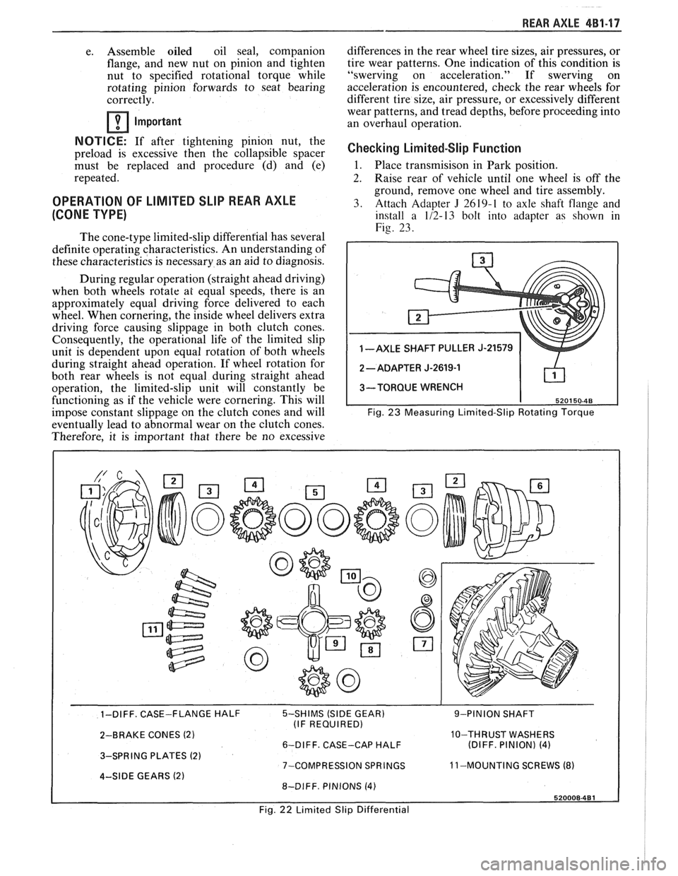
1 -AXLE SHAFT PULLER J-21579
3-TORQUE WRENCH
Fig.
23 Measuring Limited-Slip Rotating Torque
- - 1-DIFF. CASE-FLANGE HALF 5-SHIMS (SIDE GEAR) 9-PINION SHAFT
(IF REQUIRED)
2-BRAKE CONES
(2) 10-THRUST WASHERS
6-DIFF. CASE-CAP HALF (DIFF. PINION) (4)
3-SPRING PLATES (2) 7-COMPRESSION SPRINGS 11
-MOUNTING SCREWS (8) 4-SIDE GEARS (2) 8-DIFF. PINIONS (4)
Fig. 22 Limited Slip Differential