tow PONTIAC FIERO 1988 Service User Guide
[x] Cancel search | Manufacturer: PONTIAC, Model Year: 1988, Model line: FIERO, Model: PONTIAC FIERO 1988Pages: 1825, PDF Size: 99.44 MB
Page 214 of 1825
FRONT SUSPENSION 3C3
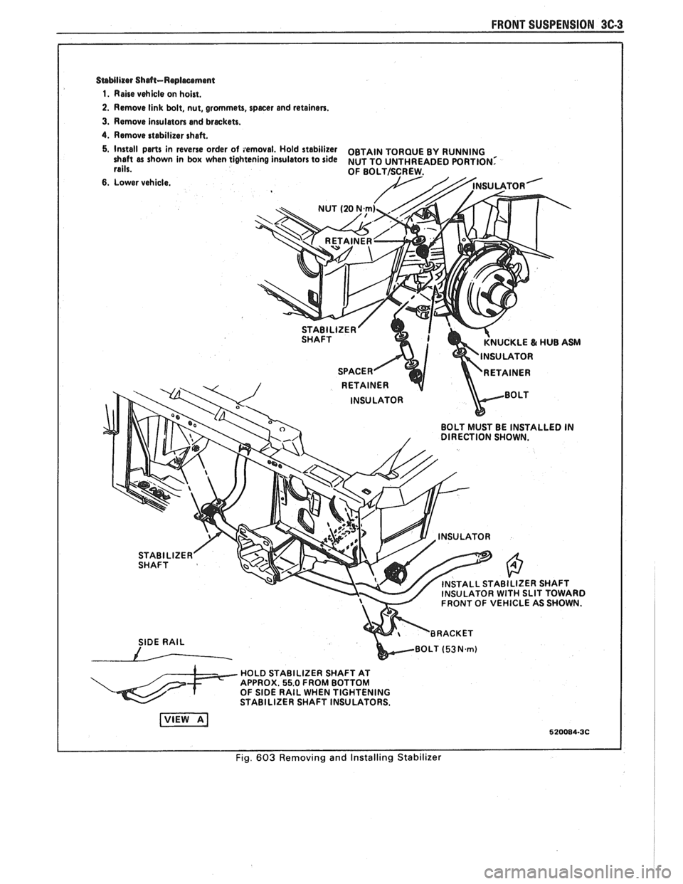
SaMlizer Sh&-Replrcrmmt
1. Rehe vehicle on hoist.
2. Remove link bolt, nut, grommets, specer and retainers.
3. Remove insulators end breckets.
4. Remove stabilizer shaft.
5.
Install ports in reverse order of iemova!. Hold stabilizer OBTAIN TORQUE BY RUNNING shaft as shown in box when tighten~ng ~nsulators to s~de NUT TO UNTHREADED PORTION: rails. OF BOLTISCREW.
6. Lower vehicle.
NUCKLE
6r HUB AW
SHAFT L STABILIZER SHAFT
TOR
WITH SLIT TOWARD
OF VEHICLE AS SHOWN.
SlDE RAIL
A
HOLD STABILIZER SHAFT AT
APPROX. 55.0 FROM BOTTOM
OF SlDE RAlL WHEN TIGHTENING
STABILIZER SHAFT INSULATORS.
I Fig. 603 Removing and Installing Stabilizer I
~
Page 221 of 1825
3C-18 FRONT SUSPENSION
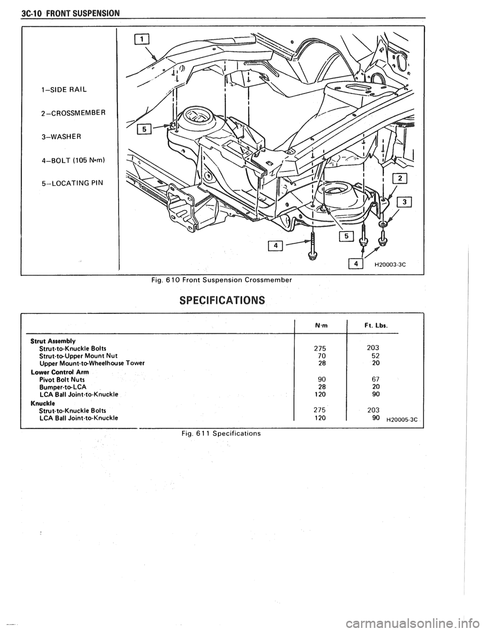
1-SIDE RAIL
2-CROSSMEMBER 3-WASH E
R
4-BOLT (105 Nwm)
5-LOCATING PIN
I I Fig. 6 10 Front Suspension Crossmember
SPEGIFICA"T0NS
Strut Aarembly Stmt-to-Knuckle Bolts
Strut-to-Upper Mount Nut
Upper Mount-to-Wheelhouse Tower
Lower Contrd Arm
Pivot
Rolt Nuts
Bumper-to-LCA
LCA Ball Joint-to-Knuckle
Knuckle Strut-to-Knuckle Bolts
LCA Ball Joint-to-Knuckle
Ft. Lbs.
Fig.
6 1 1 Specifications
Page 224 of 1825
REAR SUSPENSION 30-3
1. Position springs and insulators in spring seats and
raise rear axle until rear axle supports weight of
vehicle at normal curb height position.
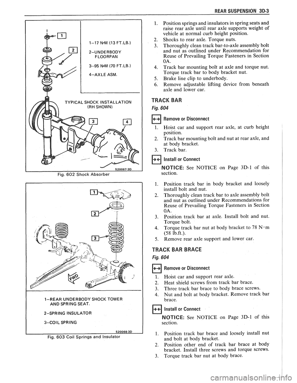
2. Shocks to rear axle. Torque nuts. 1-17 N.M (13 FT.LB.1 3. Thoroughly clean track bar-to-axle assembly bolt
2-UNDERBODY and nut as outlined under Recommendation for
Reuse of Prevailing Torque Fasteners in Section
3-95 NeM (70 FT.LB.) 4. Track bar mounting bolt at axle and torque nut.
4-AXLE ASM. Torque track bar to body bracket nut.
5. Brake line clip to underbody.
6. Remove adjustable lifting device from beneath
axle and lower car.
TYPICAL SHOCK INSTALLATION TRACK BAR (RH SHOWN)
Remove or Disconnect
at body bracket.
3. Track bar.
Install or Connect
NOTICE: See NOTICE on Page 3D-1 of this
1. Position track bar in body bracket and loosely
install bolt and nut.
2. Thoroughly clean track bar to axle assembly bolt
and nut as outlined under Recommendations for
Reuse of Prevailing Torque Fasteners in Section
3. Position track bar at axle. Install bolt and nut.
4. Torque track bar nut at body bracket to 78 Nem
5. Remove rear axle support and lower car.
TRACK BAR BRACE
1. Hoist car and support rear axle.
2. Heat shield screws from track bar brace.
3. Three track bar brace to body brace screws.
4. Nut and bolt at body bracket. Remove track bar 1-REAR UNDERBODY SHOCK TOWER
AND SPRING SEAT.
2-SPRING INSULATOR
NOTICE: See NOTICE on Page 3D-1 of this 3-COIL SPRING
1. Position track bar brace and loosely install nut Fig. 603 Coil Springs and Insulator and bolt at body bracket.
2. Position other end of track bar brace at body
bracket. Install three screws and torque screws.
3. Torque track bar nut at body brace.
Page 237 of 1825
3E-6 TIRES AND WHEELS
runout of the tire or wheel. Use a dial indicator on the
tire's sidewall and on the rim's flange to determine if
there is excessive lateral
runout.
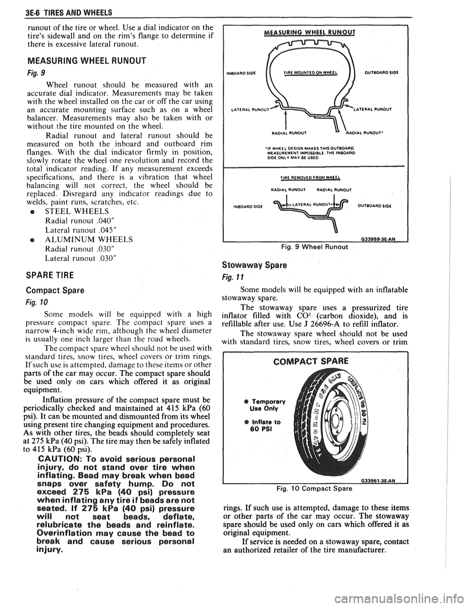
MEASURING WHEEL RUNOUT
Fig. 9
Wheel runout should be measured with an
accurate dial indicator. Measurements may be taken
with the wheel installed on the car or off the car using
an accurate mounting surface such as on a wheel
balancer. Measurements may also be taken with or
without the tire mounted on the wheel.
Radial
runout and lateral runout should be
measured on both the inboard and outboard rim
flanges. With the dial indicator firmly in position,
slowly rotate the wheel one revolution and record the
total indicator reading. If any measurement exceeds
specifications, and there is a vibration that wheel
balancing will not correct, the wheel should be
replaced. Disregard
any indicator readings due to
welds, paint runs, scratches, etc.
e STEEL WHEELS
Radial
runout .040"
Lateral runout .045"
e ALUMINUM WHEELS
Radial
runout .030"
Lateral runout .030"
SPARE TIRE
Compact Spare
Fig. 10
Some models will be equipped with a high
pressure compact spare. The compact spare uses a
narrow 4-inch wide rim, although the wheel diameter
is usually one inch larger than the road wheels.
The compact spare wheel should not be used with
standard tires, snow tires, wheel covers or trim rings.
If such use is attempted, damage to these items or other
parts of the car may occur. The compact spare should
be used only on cars which offered it as original
equipment.
Inflation pressure of the compact spare must be
periodically checked and maintained at
415 kPa (60
psi). It can be mounted and dismounted from its wheel
using present tire changing equipment and procedures.
As with other tires, the beads should completely seat
at
275 kPa (40 psi). The tire may then be safely inflated
to
415 kPa (60 psi).
CAUTION: To avoid serious personal
injury, do not stand over tire when
inflating. Bead may break when bead
snaps over safety hump. Do not
exceed
275 kPa (40 psi) pressure
when inflating any tire
if beads are not
seated. If
275 kPa (40 psi) pressure
will not seat beads, deflate,
relubricate the beads and reinflate.
Overinflation may cause the bead to
break and cause serious personal
injury.
INBOARD SIDE TIRE MOUNTED ON fVHEEL OUTBOARD SIDE
RADIAL
RUNOUT'
'IF WHEEL DESIGN MAKES THISOUTBOARD MEASUREMENT IMPOSSIBLE. THE INBOARD
SIDE ONLY MAY BE USED
I RADIAL RUNOUT RADIAL RUNDUT I
INBOARD SIDE OUTBOARD SIDE
Fig. 9 Wheel Runout
Stowaway Spare
Fig. 11
Some models will be equipped with an inflatable
stowaway spare.
The stowaway spare uses a pressurized tire
inflator filled with
C02 (carbon dioxide), and is
refillable after use. Use
J 26696-A to refill inflator.
The stowaway spare wheel should not be used
with standard tires, snow tires, wheel covers or trim
@ Temporary
Use Only
@ Inflate to 80 PSI
Fig. 10 Compact Spare
rings. If such use is attempted, damage to these items
or other parts of the car may occur. The stowaway
spare should be used only on cars which offered
it as
original equipment.
If service is needed on a stowaway spare, contact
an authorized retailer of the tire manufacturer.
Page 238 of 1825
TIRES AND WHEELS 3E-7
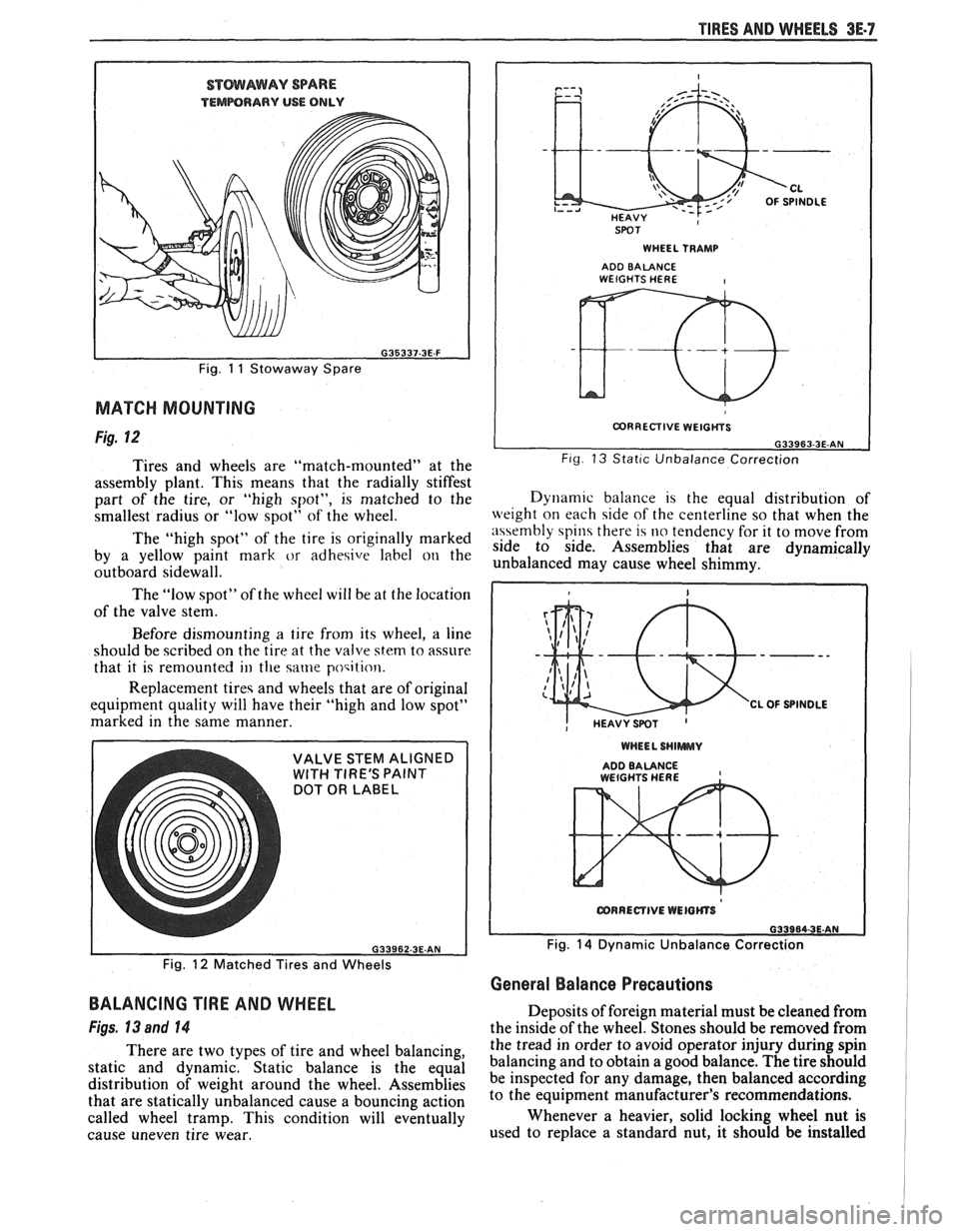
STMAWAY SPARE
TEMPORARY USE ONLV
Fig. 11 Stowaway Spare
MATCH MOUNTING
Fig. 12
Tires and wheels are "match-mounted" at the
assembly plant. This means that the radially stiffest
part of the tire, or "high spot", is matched to the
smallest radius or "low spot" of the wheel.
The "high spot" of the tire is originally marked
by a yellow paint mark
or adhesive label on the
outboard sidewall.
The "low spot" of the wheel will be at the location
of the valve stem.
Before dismounting
a tire from its wheel, a line
should be scribed on the tire at the valve
stem to assure
that it is remounted
ill the same poqition.
Replacement tireq and wheels that are of original
equipment quality will have their "high and low spot"
marked in the same manner.
DOT OR LABEL
SPOT I WHEEL TRAMP I
ADD BALANCE WEIGHTS HERE I
I CORRECTIVE WEIGtiYS I
L G33963-3E.AN Fig 13 Stat~c Unbalance Correction
Dynam~c balance 1s the equal distribution of
weight on each side of the centerline so that when the
n\\embly spin there 14 no tendency for it to move from
side to side. Assemblies that are dynamically
unbalanced may cause wheel shimmy.
WHEEL SHlWWUV
ADDBALANCE , WEtGHTS HERE
Fig. 14 Dynamic Unbalance Correction
Fig.
12 Matched Tires and Wheels
General Balance Precautions
BALANCING TIRE AND WHEEL
Figs, 13 and 14
There are two types of tire and wheel balancing,
static and dynamic. Static balance is the equal
distribution of weight around the wheel. Assemblies
that are statically unbalanced cause a bouncing action
called wheel tramp. This condition will eventually
cause uneven tire wear. Deposits
of foreign material must be cleaned from
the inside of the wheel. Stones should be removed from
the tread in order to avoid operator injury during spin
balancing and to obtain a good balance. The tire should
be inspected for any damage, then balanced according
to the equipment manufacturer's recommendations.
Whenever a heavier, solid locking wheel nut is
used to replace a standard nut, it should
be installed
Page 239 of 1825
3E-8 TIRES AND WHEELS
nearest the valve stem, and a 1/2 ounce balance weight
should be added 180" opposite the locking nut on the
wheel's inboard side.
When rotating tires, always re-install the locking
nut nearest the tire valve stem so that it remains
opposite the 1/2 ounce balance weight. This procedure
will improve the on-car wheel balance by compensating
for the heavy locking wheel nut.
Off-Car Balancing
Most electronic off-car balancers are more
accurate than the on-car spin balancers. They are easy
to use and give a dynamic (two plane) balance.
Although they do not correct for drum or rotor
unbalance as does on-car spin balancing, this is
overcome by their accuracy (usually to within 1/8
ounce). When balancing off-car, the wheel should
locate on the balancer with a cone through the back
side of the center pilot hole (not by the wheel stud
holes).
On-Car Balancing
When needed, on-car balancing will help correct
vibrations due to brake drum, rotor, and wheel cover
imbalance.
When balancing on car, do not remove the
balance weights from the off-car dynamic balance. If
more than one ounce of additional weight is required,
it should be split between the inner and outer rim
flange.
NOTICE: The driven tire and wheel assemblies
should be spun using the engine. Limit speed as
stated in the following Caution.
CAUTION: Do not spin the drive
wheels faster than
35 mph (55 km/h)
as indicated by the speedometer. This
limit is necessary because the
speedometer indicates only one-half
of the actual wheel speed when one
drive wheel is spinning and the other
drive wheel is stopped. Personal injury
and damage may result from high
speed spinning.
CAUTION: On cars equipped with
limited slip rear axles, do not attempt
to balance a tire on a
drive wheel with
the other drive wheel on the ground.
The car may drive through this wheel
and cause the car to move
unexpectedly, resulting in personal
injury and property damage.
To distinguish between standard rear axle and
limited slip, raise rear of car so both tires are clear of
ground. With the transmission in park (in gear with
manual transmission), attempt to turn one wheel by
hand. If the wheel can be turned, it is a standard rear
axle; if the wheel cannot be turned, it is a limited slip
rear axle. Also, check for Limited Slip
(G80) on Service
Parts Identification label.
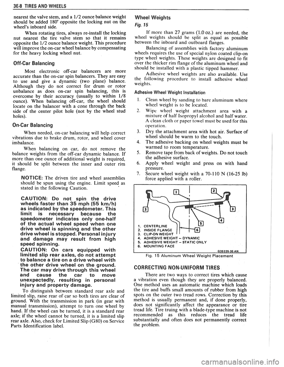
Wheel Weights
Fig. 15
If more than 27 grams (1.0 oz.) are needed, the
wheel weights should be split as equal as possible
between the inboard and outboard flanges.
Balancing of' assemblies with factory aluminum
wheels requires the use of special nylon coated clip-on
type wheel weights. These weights are designed to fit
over the thicker rim flange of the aluminum wheel and
should be installed with a plastic tipped hammer.
Adhesive wheel weights are also available. Use
the following procedure to install adhesive wheel
weights.
Adhesive Wheel Weight Installation
1. Clean wheel by sanding to bare aluminum where
wheel weight is to be located.
2. Wipe wheel weight attachment area with a
mixture of half Isopropyl alcohol and half water.
A clean cloth or paper towel niust be used for this
operat ion.
3. Dry the attachment area with hot air. Surface of
wheel should be warm to the touch.
4. The adhesive backing on wheel weights must be
warmed to room temperature.
5. Remove tape from back of weights. Do not touch
the adhesive surface.
6. Apply wheel weight and press on with hand
pressure.
7. Secure wheel weight with a 70-1 10
N (16-25 lb)
force applied with a roller.
CENTERLINE
1 INSIDE FLANGE CLIPBN WEIGHT 4. ADHESIVE WEIGHT - DYNAMIC 5. ADHESIVE WEIGHT -STATIC ONLY 6. MOUNTING FACE
Fig. 15 Aluminum Wheel Weight Placement
CORRECTING NON-UNIFORM TIRES
There are two ways to correct tires which cause
a vibration even though they are properly balanced.
One method uses an automatic machine which loads
the tire and buffs small amounts of rubber from high
spots on the outer two tread rows. Correction by this
method is usually permanent and, if done properly,
does not significantly affect the appearance or tire
tread life. Tire truing with a blade-type
machine is not
recommended as this reduces the tread life
substantially and often does not permanently correct
the problem.
Page 249 of 1825
4A-8 PROPELLER SHAFT
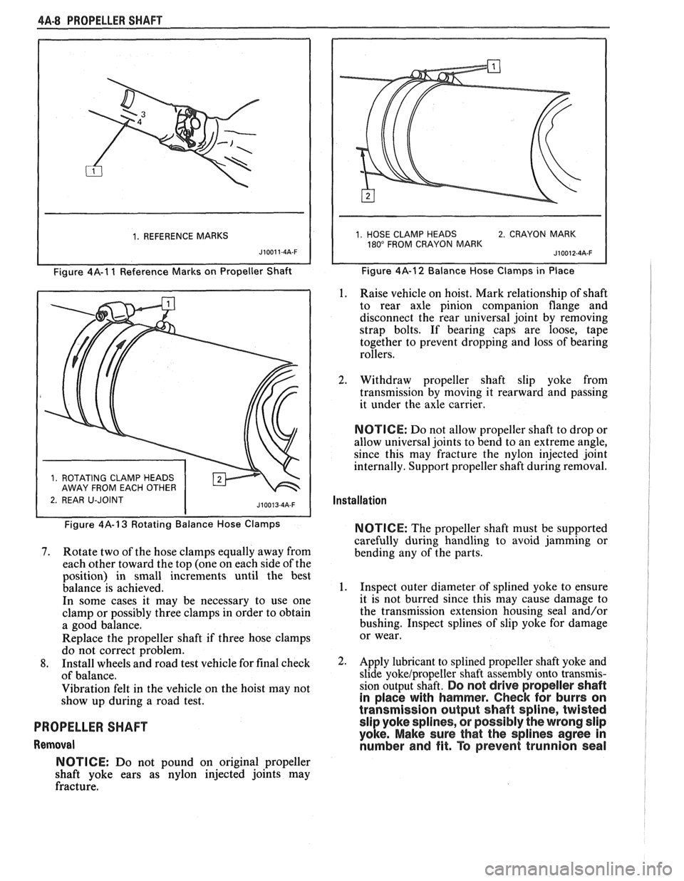
1. REFERENCE MARKS
J10011-4A-F
Figure 4A-1 1 Reference Marks on Propeller Shaft
1 2. REAR U-JOINT
1. HOSE CLAMP HEADS 2. CRAYON MARK 180" FROM CRAYON MARK
Figure 4A-12 Balance Hose Clamps in Place
1. Raise vehicle on hoist. Mark relationship of shaft
to rear axle pinion companion flange and
disconnect the rear universal joint by removing
strap bolts. If bearing caps are loose, tape
together to prevent dropping and loss of bearing
rollers.
2. Withdraw propeller shaft slip yoke from
transmission by moving it rearward and passing
it under the axle carrier.
NOTICE: Do not allow propeller shaft to drop or
allow universal joints to bend to an extreme angle,
since this may fracture the nylon injected joint
internally. Support propeller shaft during removal.
Installation
Figure 4A-13 Rotating Balance Hose Clamps
7. Rotate two of the hose clamps equally away from
each other toward the top (one on each side of the
position) in small increments until the best
balance is achieved.
In some cases it may be necessary to use one
clamp or possibly three clamps in order to obtain
a good balance.
Replace the propeller shaft if three hose clamps
do not correct problem.
8. Install wheels and road test vehicle for final check
of balance.
Vibration felt in the vehicle on the hoist may not
show up during a road test.
PROPELLER SHAFT
Removal NOTICE:
The
propeller shaft must be supported
carefully during handling to avoid jamming or
bending any of the parts.
1. Inspect outer diameter of splined yoke to ensure
it is not burred since this may cause damage to
the transmission extension housing seal and/or
bushing. Inspect splines of slip yoke for damage
or wear.
Apply lubricant to splined propeller shaft yoke and
slide yokelpropeller shaft assembly onto transmis-
sion output shaft.
Do not drive propeller shaft
in place with hammer.
Check for burrs on
transmission output shaft spline, twisted slip yoke splines, or possibly the wrong slip
yoke. Make sure that the splines agree in
number and fit. To prevent trunnion seal
NOTICE: Do not pound on original propeller
shaft yoke ears as nylon injected joints may
fracture.
Page 260 of 1825
REAR AXLE 481-7
ON-VEHICLE SERVICE
CARRIER COVER AND GASKET
Remove or Disconnect
1. Having
a container in place remove drain plug
with tool
J-35117,remove cover bolts and pry
cover loose to drain lubricant.
2. Make sure both
gasket sealing surfaces are clean.
Install or Connect
Use cover gasket (do not assemble with
sealant alone).
NOTICE: Apply locktite part No. 573, GM Part
Nos. 1052080, or 1052279 or equivalent to cover
bolts before installing cover. If sealant is not applied
bolts may loosen causing fluid leak and damage to
rear axle assembly.
1. Torque cover bolts in a crosswise pattern to
insure uniform draw on gasket. Torque
26 N.m
(20 1b.ft.).
2. Fill with lubricant to bottom of filler plug hole.
Refer to specifications for correct lubricant usage
and quantity.
AXLE SHAFT
Remove or Disconnect
1. Wheel
and brake components as necessary.
2. The
four nuts holding the brake anchor plate and
outer bearing retainer.
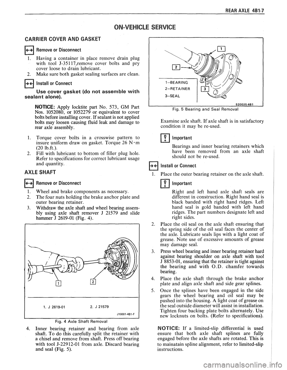
3. Withdraw the axle shaft and wheel bearing assem-
bly using axle shaft remover
J 21579 and slide
hammer
J 2619-01 (Fig. 4).
Fig. 4 Axle Shaft Removal
4. Inner
bearing retainer and bearing from axle
shaft. To do this carefully split the retainer with
a chisel and remove from shaft. Press off bearing
with tool
5-22912-01 from axle. Discard bearing
and seal (Fig. 5).
Fig. 5 Bearing and Seal Removal
Examine axle shaft. If axle shaft is in satisfactory
condition it may be re-used.
Important
Bearings and inner bearing retainers which
have been removed from an axle shaft
should not be re-used.
Install or Connect
1. Place the outer bearing retainer on the axle shaft.
Important
Right and left hand axle shaft seals are
different in construction. Right hand seal is
black banded with right hand ridges. Left
hand seal is gold banded with left hand
ridges. The part numbers designate left and
right sides.
2. Place the oil seal on the axle shaft ensuring that
the spring side of the oil seal faces the center of
the axle. Lubricate seals lips with a light coat of
grease. Note use of excessive amounts of grease
may damage seal.
3. Press wheel bearing and inner bearing retainer hard
against bearing shoulder on axle shaft with tool
J 8853-01, ensuring that the retainer is tight against
the bearing and with
O.D. chamfer towards
bearing.
4. Place the axle shaft through the brake anchor
plate and align axle shaft and side gear splines.
5. Once the splines have been engaged in the side
gears the wheel bearing and oil seal may be
pushed into the housing.
A light coat of grease on
the seal outside diameter will assist in installation.
Tighten four backing plate bolts alternately. Use
new locknuts on bolts. (Refer to specifications).
NOTICE: If a limited-slip differential is used
ensure that both axle shaft splines are fully
engaged before the axle shafts are rotated. This is
to mainatain spline alignment, refer to limited-slip
instructions.
Page 261 of 1825
481.8 REAR AXLE
6. Replace
brake components and wheel.
7. Tighten wheel nuts and lower vehicle.
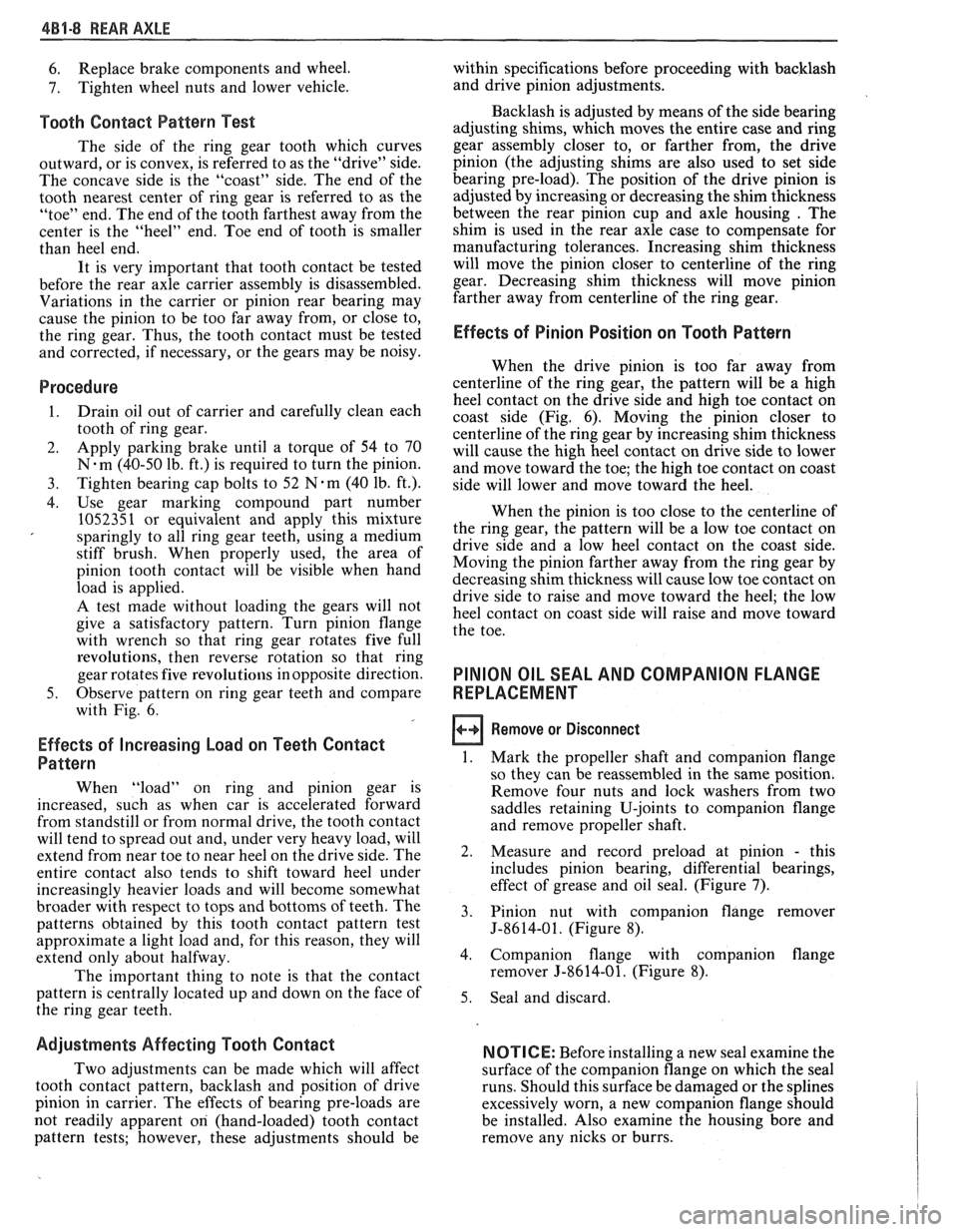
Tooth Contact Pattern Test
The side of the ring gear tooth which curves
outward, or is convex, is referred to as the "drive" side.
The concave side is the "coast" side. The end of the
tooth nearest center of ring gear is referred to as the
"toe" end. The end of the tooth farthest away from the
center is the "heel" end. Toe end of tooth is smaller
than heel end.
It is very important that tooth contact be tested
before the rear axle carrier assembly is disassembled.
Variations in the carrier or pinion rear bearing may
cause the pinion to be too far away from, or close to,
the ring gear. Thus, the tooth contact must be tested
and corrected, if necessary, or the gears may be noisy.
Procedure
1. Drain
oil out of carrier and carefully clean each
tooth of ring gear.
2. Apply parking brake until a torque of 54 to 70
N-m (40-50 lb. ft.) is required to turn the pinion.
3. Tighten bearing cap bolts to 52 N-m (40 lb. ft.).
4. Use gear marking compound part number
1052351 or equivalent and apply this mixture
sparingly to all ring gear teeth, using a medium
stiff brush. When properly used, the area of
pinion tooth contact will be visible when hand
load is applied.
A test made without loading the gears will not
give a satisfactory pattern. Turn pinion flange
with wrench so that ring gear rotates five full
revolutions, then reverse rotation so that ring
gear rotates five
revolutio~ls in opposite direction.
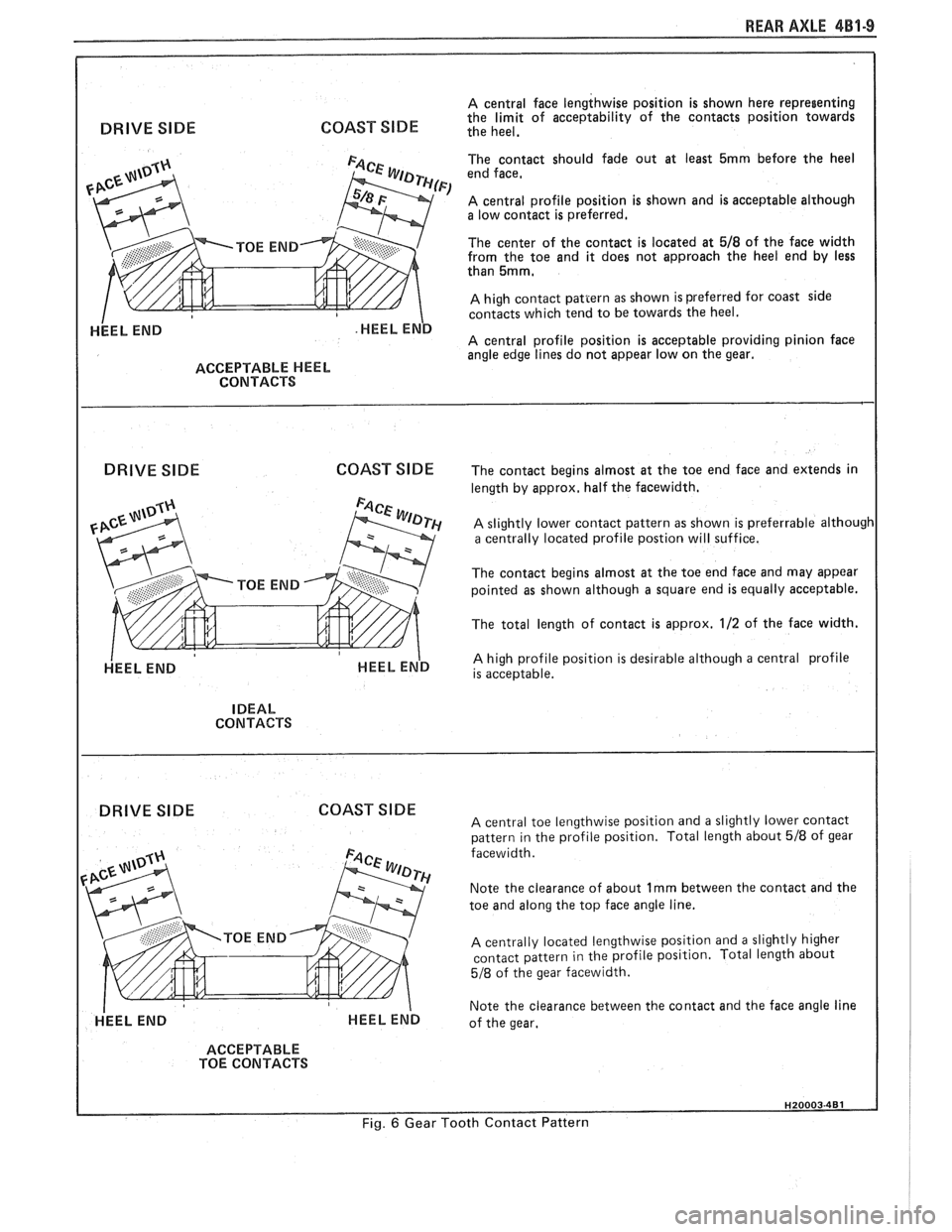
5. Observe pattern on ring gear teeth and compare
with Fig.
6.
Effects of Increasing Load on Teeth Contact
Pattern
When "load" on ring and pinion gear is
increased, such as when car is accelerated forward
from standstill or from normal drive, the tooth contact
will tend to spread out and, under very heavy load, will
extend from near toe to near heel on the drive side. The
entire contact also tends to shift toward heel under
increasingly heavier loads and will become somewhat
broader with respect to tops and bottoms of teeth. The
patterns obtained by this tooth contact pattern test
approximate a light load and, for this reason, they will
extend only about halfway.
The important thing to note is that the contact
pattern is centrally located up and down on the face of
the ring gear teeth.
Adjustments Affecting Tooth Contact
Two adjustments can be made which will affect
tooth contact pattern, backlash and position of drive
pinion in carrier. The effects of bearing pre-loads are
not readily apparent
on (hand-loaded) tooth contact
pattern tests; however, these adjustments should be within
specifications before proceeding with backlash
and drive pinion adjustments.
Backlash is adjusted by means of the side bearing
adjusting shims, which moves the entire case and ring
gear assembly closer to, or farther from, the drive
pinion (the adjusting shims are also used to set side
bearing pre-load). The position of the drive pinion is
adjusted by increasing or decreasing the shim thickness
between the rear pinion cup and axle housing
. The
shim is used in the rear axle case to compensate for
manufacturing tolerances. Increasing shim thickness
will move the pinion closer to centerline of the ring
gear. Decreasing shim thickness will move pinion
farther away from centerline of the ring gear.
Effects of Pinion Position on Tooth Pattern
When the drive pinion is too far away from
centerline of the ring gear, the pattern will be a high
heel contact on the drive side and high toe contact on
coast side (Fig. 6). Moving the pinion closer to
centerline of the ring gear by increasing shim thickness
will cause the high heel contact on drive side to lower
and move toward the toe; the high toe contact on coast
side will lower and move toward the heel.
When the pinion is too close to the centerline of
the ring gear, the pattern will be a low toe contact on
drive side and a low heel contact on the coast side.
Moving the pinion farther away from the ring gear by
decreasing shim thickness will cause low toe contact on
drive side to raise and move toward the heel; the low
heel contact on coast side will raise and move toward
the toe.
PINION OIL SEAL AND COMPANION FLANGE
REPLACEMENT
Remove or Disconnect
1. Mark the propeller shaft and companion flange
so they can be reassembled in the same position.
Remove four nuts and lock washers from two
saddles retaining
U-joints to companion flange
and remove propeller shaft.
2. Measure and record preload at pinion - this
includes pinion bearing, differential bearings,
effect of grease and oil seal. (Figure
7).
3. Pinion nut with companion flange remover
J-8614-01. (Figure 8).
4. Companion flange with companion flange
remover
5-8614-01. (Figure 8).
5. Seal and discard.
NOTICE: Before installing a new seal examine the
surface of the companion flange on which the seal
runs. Should this surface be damaged or the splines
excessively worn, a new companion flange should
be installed. Also examine the housing bore and
remove any nicks or burrs.
Page 262 of 1825
REAR AXLE 481-9
A central face lengthwise position is shown here representing
COAST SlDE the limit of acceptability of the contacts position towards DRIVE SIDE the heel.
ACCEPTABLE HEEL
CONTACTS
DRIVE SlDE COAST
SlDE
HEEL END
The contact should fade out at least 5mrn before the heel
end face,
A central profile position is shown and is acceptable alrhough a low contact is preferred.
The center of the contact is located at
518 of the face width
from the toe and it does not approach the heel end by less
than
5mm,
A high contact pattern as shown is preferred for coast side
contacts which tend to be towards the heel.
A central profile position is acceptable providing pinion face
angle edge lines do not appear low on the gear.
The contact begins almost at the toe end face and extends in
length by approx, half the facewidth.
A slightly lower contact pattern as shown is preferrable although a centrally located profile postion will suffice.
The contact begins almost at the toe end face and may appear
pointed as shown although a square end is equally acceptable.
The total length of contact is approx.
112 of the face width.
A high profile position is desirable although a central profile
is acceptable.
IDEAL
CONTACTS
DRIVE SIDE COAST SIDE A central toe lengthwise position and a slightly lower contact
pattern in the profile position. Total length about 518 of gear
facewidth.
Note the clearance of about
1 rnrn between the contact and the
toe and along the top face angle line.
A centrally located lengthwise position and a slightly higher
contact pattern in the profile position. Total length about
518 of the gear facewidth.
Note the clearance between the contact and the face angle line
of the gear.
ACCEPTABLE
TOE CONTACTS
Fig. 6 Gear Tooth Contact Pattern