center console PONTIAC FIERO 1988 Service Repair Manual
[x] Cancel search | Manufacturer: PONTIAC, Model Year: 1988, Model line: FIERO, Model: PONTIAC FIERO 1988Pages: 1825, PDF Size: 99.44 MB
Page 1211 of 1825
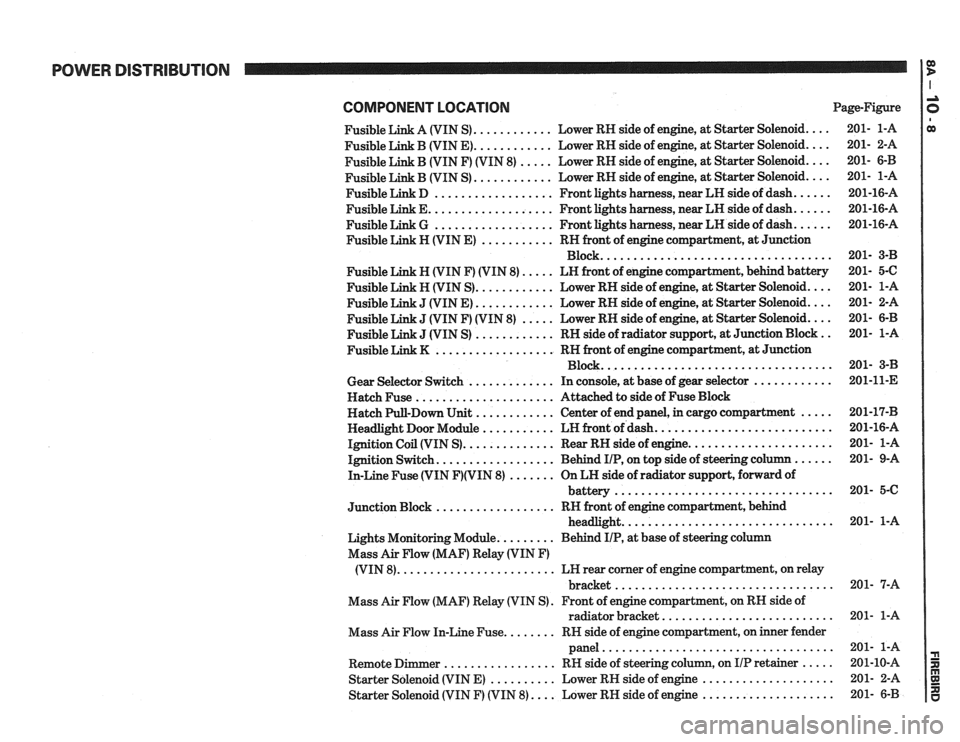
POWER DISTRIBUTION
COMPONENT LOCATlON Page-Figure
Fusible Link A (VIN S)
............ Lower RH side of engine. at Starter Solenoid ....
Fusible Link B (VIN E) ............ Lower RH side of engine. at Starter Solenoid ....
Fusible Link B (VIN F) (VIN 8) ..... Lower RH side of engine. at Starter Solenoid ....
............ Fusible Link B (VIN S) Lower
RH side of engine. at Starter Solenoid ....
Fusible Link D .................. Front lights harness. near LH side of dash ......
Fusible Link E ................... Front lights harness. near LH side of dash ......
Fusible Link G .................. Front lights harness. near LH side of dash ......
Fusible Link H (VIN E) ........... RH front of engine compartment. at Junction
Block
...................................
Fusible Link N (VIN F) (VIN 8) ..... LN front of engine compartment. behind battery
Fusible Link H (VIN S)
............ Lower RH side of engine. at Starter Solenoid ....
J (VIN E) ............ Lower RH side of engine, at Starter Solenoid ....
J (VIN F) (VIN 8) ..... Lower RH side of engine, at Starter Solenoid ....
J (VIN S) ............ RH side of radiator support. at Junction Block ..
.................. Fusible Link K RN front of engine compartment. at Junction
Block
...................................
Gear Selector Switch ............. In console, at base of gear selector ............
Hatch Fuse ..................... Attached to side of Fuse Block
Hatch Pull-Down Unit
............ Center of end panel, in cargo compartment .....
Headlight Door Module ........... LH front of dash ...........................
Ignition Coil (VIN S) .............. Rear RH side of engine ......................
Ignition Switch .................. Behind IIP. on top side of steering column ......
In-Line Fuse (VIN F)(VIN 8) ....... On LH side of radiator support. forward of
................................. battery
.................. Junction Block RH front of engine compartment. behind
................................ headlight
Lights Monitoring Module
......... Behind IIP. at base of steering column
Mass Air Flow (MAF) Relay (VIN
F)
........................ (VIN 8) LH rear corner of engine compartment, on relay
................................. bracket
Mass Air Flow (MAF) Relay (VIN S)
. Front of engine compartment. on RH side of
radiator bracket
..........................
Mass Air Flow In-Line Fuse ........ RN side of engine compartment, on inner fender
panel
...................................
Remote Dimmer ................. RH side of steering column. on IIP retainer .....
Starter Solenoid (VIN E) .......... Lower RH side of engine ....................
Starter Solenoid (VIN F) (VIN 8) .... Lower RH side of engine ....................
Page 1215 of 1825
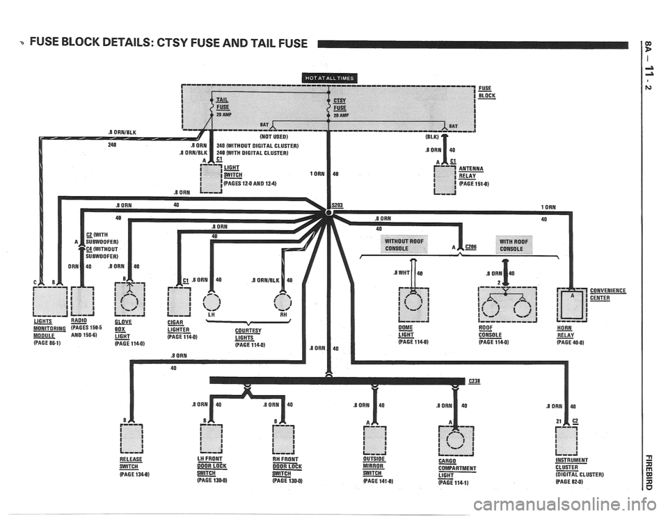
a FUSE BLOCK DETAILS: CTSY FUSE AND TAIL FUSE I:
.8 ORNIBLK
CONVENIENCE
CENTER
LIGHT
- CONSOLE RELAY (PAGE 1140) (PAGE 114-0) (PAGE 40-0)
- SWITCH DOOR LOCK DOOR LOCK MIRROR COMPARTMENT CLUSTER
(PAGE 1340) - S-W a LIGHT - (DIGITAL CLUSTER)
(PAGE 130-0) (PAGE 130-0) (PAGE 141-0) (PAGE 114-1) (PAGE 82-0)
Page 1250 of 1825
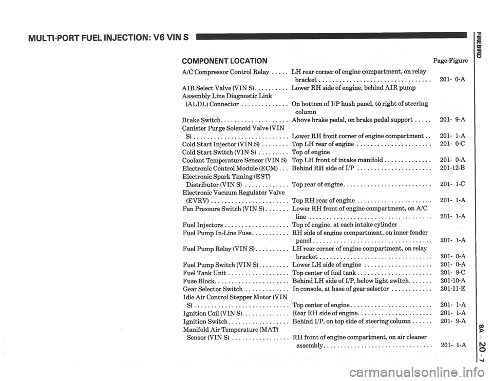
MULTI-PORT FUEL INJECTION: V6 VIN S
COMPONENT LOCATION
AIC Compressor Control Relay ..... LH rear corner of engine compartment, on relay
................................. bracket
AIR Select Valve (VIN S)
.......... Lower RN side of engine, behind AIR pump
Assembly Line Diagnostic Link
(ALDL) Connector
.............. On bottom of IIP hush panel, to right of steering
column
Brake Switch.
................... Above brake pedal, on brake pedal support .....
Canister Purge Solenoid Valve (VIN
............................ .. S) Lower RH front
corner of engine compartment
Cold Start Injector (VIN S)
........ Top LH rear of engine ......................
Cold Start Switch (VIN S) ......... Top of engine
Coolant Temperature Sensor (VIN S) Top LN front of intake manifold.
.............
Electronic Control Module (ECM) ... Behind RH side of IIP ......................
Electronic Spark Timing (EST)
......................... Distributor (VIN S) ............. Top rear of engine.
Electronic Vacuum Regulator Valve
(EVRV)
....................... TopRHrearofengine ......................
Fan Pressure Switch (VIN S) ....... Lower RH front of engine compartment, on AIC
line ....................................
Fuel Injectors ................... Top of engine, at each intake cylinder
Fuel Pump In-Line Fuse.
.......... RH side of engine compartment, on inner fender
panel
...................................
Fuel Pump Relay (VIN S) .......... LH rear corner of engine compartment, on relay
................................. bracket
Fuel Pump Switch (VIN S)
......... Lower LH side of engine ....................
Fuel Tank Unit .................. Top center of fuel tank ......................
Fuse Block. ..................... Behind LH side of IIP, below light switch. ......
Gear Selector Switch ............. In console, at base of gear selector ............
Idle Air Control Stepper Motor (VIN
S)
............................ Topcenterofengine ........................
Ignition Coil (VIN S). ............. Rear RH side of engine. .....................
Ignition Switch. ................. Behind IIP, on top side of steering column ......
Manifold Air Temperature (MAT)
................. Sensor (VIN S) RH front of engine compartment, on air cleaner
............................... assembly. Page-Figure
Page 1264 of 1825
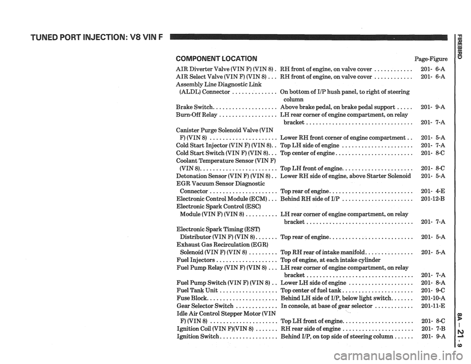
COMPONENT LOCATION Page-Figure
AIR Diverter Valve (VIN F) (VIN 8)
. RN front of engine, on valve cover ............ 201- 6-A
AIR Select Valve (VIN F) (VIN 8)
... RN front of engine, on valve cover ............ 201- 6-A
Assembly Line Diagnostic Link
(ALDL) Connector
.............. On bottom of IIP hush panel, to right of steering
column
Brake Switch.
................... Above brake pedal, on brake pedal support ..... 201- 9-A
Bum-Off Relay
.................. LN rear comer of engine compartment, on relay
bracket
................................. 201- 7-A
Canister Purge Solenoid Valve (VIN
F) (VIN 8)
..................... Lower RN front corner of engine compartment .. 201- 5-A
Cold Start Injector (VIN F) (VIN 8).
. Top LH side of engine ...................... 201- 7-A
.. ....................... Cold Start Switch (VIN F) (VIN 8). Top center of engine. 201- 8-6
Coolant
Temperature Sensor (VIN F)
..................... (VIN 8). ....................... Top LN front of engine. 201- 8-C
Detonation Sensor (VIN F) (VIN 8)
. . Lower RN side of engine, above Starter Solenoid 201- 5-A
EGR Vacuum Sensor Diagnostic
......................... Connector ..................... Top rear of engine. 201-
4-E
Electronic Control Module (ECM)
... Behind RN side of IIP ...................... 201-1243
Electronic Spark Control (ESC)
Module (VIN F) (VIN 8)
.......... LN rear corner of engine compartment, on relay
............................... bracket.. 201- 7-A
Electronic Spark Timing (EST)
Distributor (VIN
F) (VIN 8). ...... Top rear of engine. ......................... 201- 5-A
Exhaust Gas Recirculation (EGR)
Solenoid (VIN
F) (VIN 8) ......... Top RN rear of intake manifold. .............. 201- 5-A
Fuel Injectors
................... Top of engine, at each intake cylinder
Fuel Pump Relay (VIN
F) (VIN 8) ... LN rear corner of engine compartment, on relay
bracket
................................. 201- 7-A
Fuel Pump Switch (VIN
F) (VIN 8) .. Lower LN side of engine .................... 201- 8-A
Fuel Tank Unit
.................. Top center of fuel tank ...................... 201- 9-C
Fuse Block.
..................... Behind LH side of IIP, below light switch. ...... 201-10-A
Gear Selector Switch
............. In console, at base of gear selector ............ 201-11-E
Idle Air Control Stepper Motor (VIN
F) (VIN 8)
..................... Top LN front of engine. ..................... 201- 8-C
Ignition Coil (VIN
F)(VIN 8) ....... RN rear side of engine ...................... 201- 7-B
Ignition Switch.
................. Behind IIP, on top side of steering column ...... 201- 9-A
Page 1277 of 1825
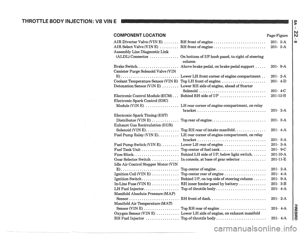
THROTTLE BODY INJECTION: V8 VIN E
COMPONENT LOCATION Page-Figure
AIR Diverter Valve (VIN E)
....... RH front of engine .........................
AIR Select Valve (VIN E) ......... RH front of engine .........................
Assembly Line Diagnostic Link
(ALDL) Connector
.............. On bottom of IIP hush panel, to right of steering
column
Brake Switch.
................... Above brake pedal, on brake pedal support .....
Canister Purge Solenoid Valve (VIN
E)
............................ Lower LH front corner of engine compartment ..
Coolant Temperature Sensor (VIN E) Top LH front of engine. .....................
Detonation Sensor (VIN E) ........ Lower RK side of engine, ahead of Starter
Solenoid
................................
Electronic Control Module (ECM) ... Behind RH side of IIP ......................
Electronic Spark Control (ESC)
Module (VIN E)
................ LH rear corner of engine compartment, on relay
................................. bracket
Electronic Spark Timing (EST)
Distributor (VIN E)
............. Top rear of engine. .........................
Exhaust Gas Recirculation (EGR)
Solenoid (VIN E).
............... Top RH rear of intake manifold. ..............
Fuel Pump Relay (VIN E). ......... LH rear corner of engine compartment, on relay
................................. bracket
Fuel Pump Switch (VIN E).
........ Lower LH rear of engine ....................
Fuel Tank Unit .................. Top center of fuel tank. .....................
Fuse Block. ..................... Behind LH side of IIP, below light switch. ......
Gear Selector Switch ............. In console, at base of gear selector ............
Idle Air Control Stepper Motor (VIN
E)
............................ Topcenterofengine ........................
Ignition Coil (VIN E) ............. Top center rear of engine ....................
Ignition Switch. ................. Behind IIP, on top side of steering column ......
In-Line Fuse (VIN E) ............. RW inner fender panel by battery .............
LW Fuel Injector. ................ Top of throttle body. .......................
Manifold Absolute Pressure (MAP)
Sensor
........................ RH front of dash. ..........................
Manifold Air Temperature (MAT)
Sensor (VIN
E) ................. Top RK rear of engine ......................
Oxygen Sensor (VIN E) ........... Lower LH side of engine, on exhaust manifold
RH Fuel Injector
................ Top of throttle body. .......................
Page 1289 of 1825
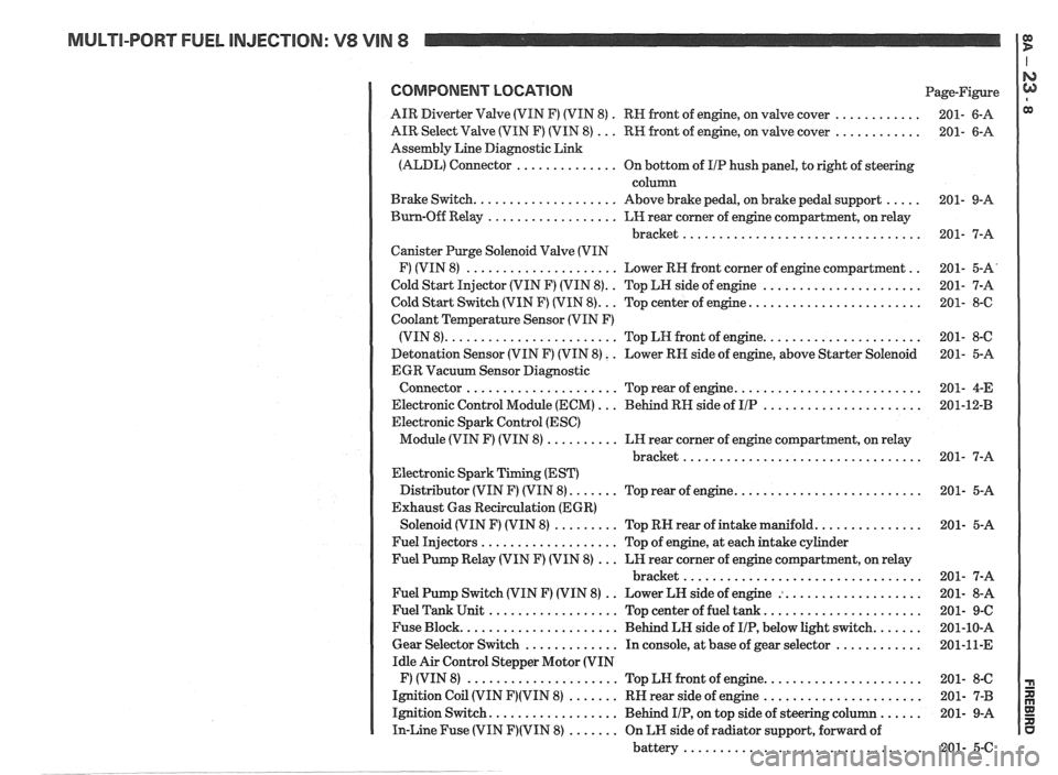
MULTI-PORT FUEL INJECTION: V8 VIN 8 It
COMPONENT LOCATION Page-Figure
. ............ AIR Diverter Valve (VIN F) (VIN 8)
RN front of engine. on valve cover 201- 6-A
............ AIR Select Valve (VIN F) (VIN 8) ... RW front of engine. on valve cover 201- 6-A
Assembly Line Diagnostic Link
(ALDL) Connector
.............. On bottom of I/P hush panel. to right of steering
column
..... Brake Switch .................... Above brake pedal. on brake pedal support 201- 9-A
Burn-Off Relay
.................. LH rear corner of engine compartment. on relay
bracket
................................. 201- 7-A
Canister Purge Solenoid Valve (VIN
.. F) (VIN 8) ..................... Lower RH front corner of engine compartment 201- 5-A'
.. ...................... Cold Start Injector (VIN F) (VIN 8) Top LH side of engine 201- 7-A
........................ Cold Start Switch (VIN F) (VIN 8) ... Top center of engine 201- 8-6
Coolant Temperature Sensor (VIN F)
...................... (VIN 8) ........................ Top LN front of engine 201- 8-C
Detonation Sensor (VIN F) (VIN 8)
. . Lower RN side of engine. above Starter Solenoid 201- 5-A
EGR Vacuum Sensor Diagnostic
.......................... Connector ..................... Top rear of engine 201- 4-E
...................... Electronic Control Module (ECM) ... Behind RH side of IIP 201-12-B
Electronic Spark Control (ESC)
Module (VIN F) (VIN 8)
.......... LH rear corner of engine compartment. on relay
bracket
................................. 201- 7-A
Electronic Spark Timing (EST)
.......................... Distributor (VIN F) (VIN 8) ....... Top rear of engine 201- 5-A
Exhaust Gas Recirculation (EGR)
............... Solenoid (VIN F) (VIN 8) ......... Top RN rear of intake manifold 201- 5-A
Fuel Injectors
................... Top of engine. at each intake cylinder
Fuel Pump Relay (VIN F) (VIN 8)
... LH rear corner of engine compartment. on relay
bracket
................................. 201- 7-A
.. ................... Fuel Pump Switch (VIN F) (VIN 8)
Lower LH side of engine : 201- 8-A
...................... Fuel Tank Unit .................. Top center of fuel tank 201- 9-C
....... Fuse Block ...................... Behind LH side of IIP. below light switch 201-10-A
............ Gear Selector Switch ............. In console. at base of gear selector 201-11-E
Idle Air Control Stepper Motor (VIN
...................... F) (VIN 8) ..................... Top LN front of engine 201- 8-C
...................... Ignition Coil (VIN F)(VIN 8) ....... RH rear side of engine 201- 7-B
...... Ignition Switch .................. Behind IIP. on top side of steering column 201- 9-A
In-Line Fuse (VIN F)(VIN 8) ....... On LH side of radiator support. forward of
battery
................................. 201- 5-C
Page 1474 of 1825
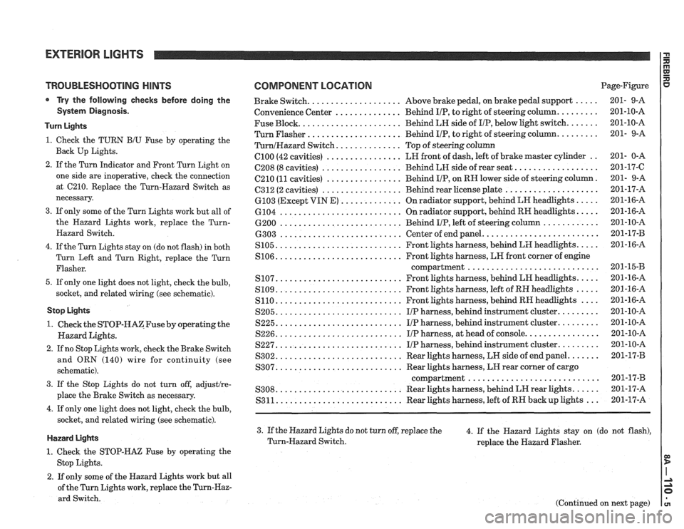
TROUBLESHOOTING HINTS
Try the following checks before doing the
System Diagnosis.
Turn Lights
1. Check the TURN B/U Fuse by operating the
Back Up Lights.
2. If the Turn Indicator and Front Turn Light on
one side are inoperative, check the connection
at
C210. Replace the Turn-Hazard Switch as
necessary.
3. If only some of the Turn Lights work but all of
the Hazard Lights work, replace the
Turn-
Hazard Switch.
4. If the Turn Lights stay on (do not flash) in both
Turn Left and Turn Right, replace the Turn
Flasher.
5. If only one light does not light, check the bulb,
socket, and related wiring (see schematic).
Stop Lights
1. Check the STOP-HAZFuse by operating the
Hazard Lights.
2. If no Stop Lights work, check the Brake Switch
and ORN (140) wire for continuity (see
schematic).
3. If the Stop Lights do not turn off, adjustlre-
place the Brake Switch as necessary.
4. If only one light does not light, check the bulb,
socket, and related wiring (see schematic).
Hazard Lights
1. Check the STOP-HAZ Fuse by operating the
Stop Lights.
2. If only some of the Hazard Lights work but all
of the Turn Lights work, replace the
Turn-Haz-
ard Switch.
COMPONENT LOCATION Page-Figure
................... ..... Brake Switch. Above
brake pedal, on brake pedal support 201- 9-A
.............. ........ Convenience
Center Behind IIP, to right of steering column. 201-10-A
Fuse Block.
..................... Behind LH side of IIP, below light switch. ...... 201-10-A
Turn Flasher
.................... Behind IIP, to right of steering column. ........ 201- 9-A
............. TurnlHazard Switch. Top of steering column
C100 (42 cavities) ................ LH front of dash, left of brake master cylinder .. 201- 0-A
................. ................. C208 (8 cavities) Behind LH side of rear seat. 201-17-C
C210
(11 cavities) ................ Behind IIP, on RN lower side of steering column. 201- 9-A
................. .................... 6312 (2 cavities) Behind rear license plate 201-17-A
............. ..... 6103 (Except VIN E) On radiator support, behind LN headlights 201-16-A
.......................... .... 6104
On radiator support, behind RH headlights. 201-16-A
.......................... ............ 6200 Behind IIP, left of steering column 201-10-A
........................ .......................... 6303 Center of end panel. 201-17-B
.......................... .... S105. Front lights harness, behind LH headlights. 201-16-A
.......................... S106. Front lights harness, LN front corner of engine
compartment..
.......................... 201-1543
.......................... .... S107. Front lights harness, behind LH headlights. 201-16-A
.......................... ..... S109. Front lights harness, left of RH headlights 201-16-A
S110. .......................... Front lights harness, behind RH headlights .... 201-16-A
S205. .......................... IIP harness, behind instrument cluster. ........ 201-10-A
S225. .......................... IIP harness, behind instrument cluster. ........ 201-10-A
S226. .......................... IIP harness, at head of console. ............... 201-10-A
S227. .......................... IIP harness, behind instrument cluster. ........ 201-10-A
S302. .......................... Rear lights harness, LW side of end panel. ...... 201-17-B
.......................... S307. Rear lights harness, LH rear corner of cargo
compartment..
.......................... 201-17-B
.......................... ..... S308. Rear lights harness, behind LH rear lights. 201-17-A
S311. .......................... Rear lights harness, left of RH backup lights ... 201-17-A
3. If the Hazard Lights do not turn off, replace the
4. If the Hazard Lights stay on (do not flash),
Turn-Hazard Switch.
replace the Hazard Flasher.
(Continued on next page)
Page 1489 of 1825
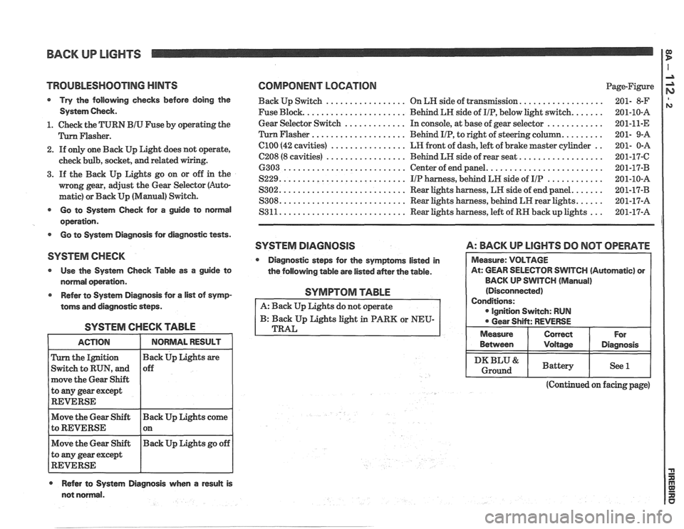
BACK UP LIGHTS
TROlJBLESHQOTlNG HINTS COMPONENT LOCATION Page-Figure
Try the following checks before doing the Back Up Switch ................. On LN side of transmission. ................. 201- 8-F
System Check. Fuse Block. ..................... Behind LH side of IIP, below light switch. ...... 201-10-A
............. ............ 1. Check the TURN BIU Fuse by operating the Gear
Selector Switch In
console, at base of gear selector
201-11-E
.................... Flasher. Flasher Behind IIP, to right of steering column. ........ 201- 9-A
2. If only one Back Up Light does not operate,
check bulb, socket,
and related
3. If the Back Up Lights go on or off in the
mong gear, adjust the Gear Selector (Auto-
matic) or Back Up (Manual) Switch.
el00 (42 cavities) ................ LR front of dash, left of brake master cylinder ..
C208 (8 cavities) ................. Behind LH side of rear seat. .................
6303 .......................... Center of end panel. ........................
S229. .......................... IIP harness, behind LH side of IIP ............
S302. .......................... Rear lights harness, LH side of end panel. ......
S308. .......................... Rear lights harness, behind LH rear lights. ..... - - Go to System Check for a guide to normal S3 11. .......................... Rear lights harness, left of RN back up lights
201-17-A ...
operation.
Go to System Diagnosis for diagnostic tests.
SYSTEM DlAGRlOSlS A: BACK UP LlGHTS DO NOT OPERATE
SYSTEM CHECK
Diagnostic steps for the symptoms listed in
Use the System Check Table as a guide to
the following table are listed
aMer the table. WlTCH (Automatic) or
normal operation. BACK
UP SWITCH
(Manual)
Refer to System Diagnosis for
a list of symp-
toms and diagnostic steps.
SYSTEM CHECK TABLE
the Ignition
Switch to RUN, and
move the Gear Shift
to
any gear except
REVERSE
Move the Gear Shift Back Up Lights come
to REVERSE 1 on - -
Move the Gear Shift Back
Up Lights go off
to any gear except
REVERSE
Refer to System Diagnosis when a result is
SYMPTOM TABLE
A: Back Up Lights do not operate
B: Back Up Lights light in PARK or NEU-
TRAL
(Continued on facing page)
not normal. Between
I Voltage I Diagnosis
I DKBLU& I Battery I See l I Ground
Page 1499 of 1825
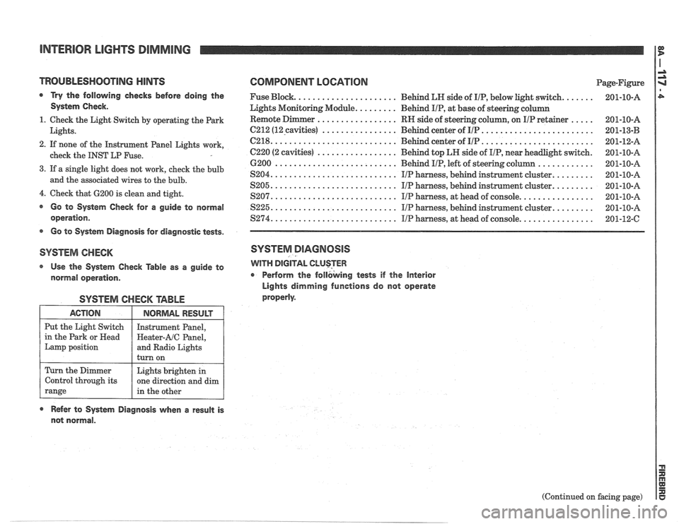
INTERIOR LIGHTS DIMMING
TROUBLESHOOTlNG HINTS COMPONENT LOGATlON Page-Figure
a Try the following checks before doing the Fuse Block. ..................... Behind LN side of IIP, below light switch. ...... 201-10-A
System Check. Lights Monitoring Module. ........ Behind IIP, at base of steering column
................. ..... 1. Check the Light Switch by operating the Park RN
side of steering column, on IIP retainer 201-10-A
................ ........................ Lights. 6212 (12-cavities) Behind center of IIP 201-13-B -
.......................... ........................ 2. If none of the Instrument Panel Lights work, C218. Behind center of IIP 201-12-A
................. check the INST LP Fuse. C220 (2 cavities) Behind top LH side of IIP, near headlight switch. 201-10-A
............ 6200 .......................... Behind IIP, left of steering column 201-10-A
3. If a single light does not work, cheek the bulb ........ S204. .......................... IIP harness, behind instrument cluster. 201-10-A and the associated wires to the bulb. ........ S205. .......................... IIP harness, behind instrument cluster. 201-10-A
4. Check that 6200 is clean and tight. ............... S207. .......................... IIP harness, at head of console. 201-10-A
@ Go to System Check for a guide to normal S225. .......................... IIP harness, behind instrument cluster. ........ 201-10-A
operation. $274. .......................... IIP harness, at head of console. ............... 201-12-C
s Go to System Diagnosis for diagnostic tests.
SYSTEM CHECK SYSTEM DIAGNOSIS
Use the System Check Table as a guide to WITH DIGITAL CLUSTER
normal operation. r Perform
the follbking tests if the Interior
Lights dimming functions do not operate
properly.
SYSTEM CHECK TABLE
ACTION
Put the Light Switch
in the Park or
Head
Lamp position
Refer to System Diagnosis when a result is
not normal.
NORMAL RESULT
Instrument Panel,
Heater-AIC Panel,
and Radio Lights
turn on
Turn the Dimmer
Control through its
range
(Continued on facing page)
Lights brighten
in
one direction and dim
in the other
Page 1504 of 1825
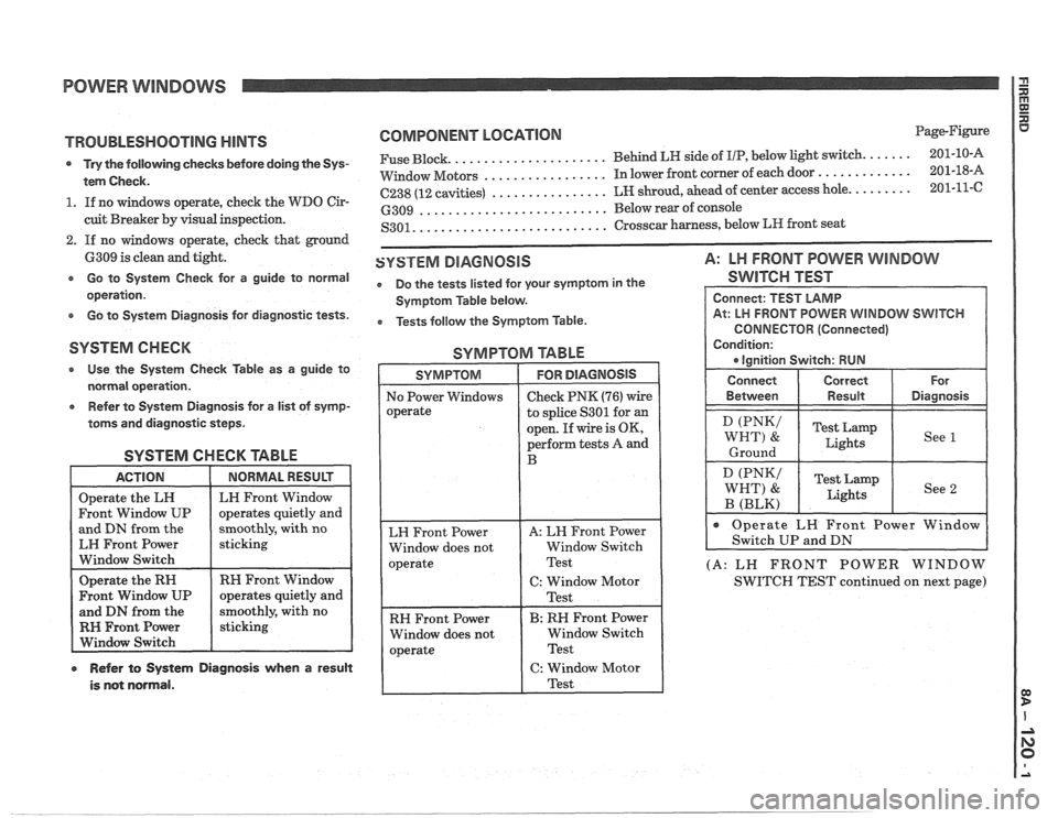
POWER WINDOWS
TROUBLESHOOTING HINTS
s Try the following checks before doing the Sys-
tem Check.
1. If no windows operate, check the WDO Cir-
cuit Breaker by visual inspection.
2. If no windows operate, check that ground
6309 is clean and tight.
e Go to System Check for a guide to normal
operation.
e Go to System Diagnosis for diagnostic tests.
COMPONENT LOCNIOM Page-Figure
..................... ...... Fuse Block. Behind LH side
of IIP, below light switch. 201-10-A
................. ............. VVindow Motors In lower front corner of each door 201-18-A
................ ........ C238 (12 cavities) LH shroud, ahead of center access hole. 201-11-C
.......................... 6309 Below rear of console
.......................... S301. Crosscar harness, below LR front seat
SYSTEM DIAGNOSIS A: LH FRONT POWER WINDOW
e Do the tests listed for your symptom in the SWITCH TEST
Symptom Table below.
e Tests follow the Symptom Table.
SYSTEM CHECK SYMPTOM TABLE
* Use the System Check Table as a guide to
normal operation.
Refer to System Diagnosis for a list of symp-
toms and diagnostic steps.
SYSTEM CHECK TABLE
and DN from the
moothly, with no
EH Front Power
Window Switch
RH Front Window
RH Front Power
r Refer to System Diagnosis when a result
is not normal.
to splice S301 for an
open. If wire is OK,
perform tests A and
RH Front Power
Window does not Window Switch
CONNECTOR (Connected)
(A: LN FRONT POWER WINDOW
SWITCH TEST continued on next page)