recommended oil PONTIAC FIERO 1988 Service Owner's Manual
[x] Cancel search | Manufacturer: PONTIAC, Model Year: 1988, Model line: FIERO, Model: PONTIAC FIERO 1988Pages: 1825, PDF Size: 99.44 MB
Page 938 of 1825
DRIVEABILITY AND EMISSIONS 5.OL (VIN F) & 5.7L (VIN 8) 6E3-C7-3
1. With a wire wheel, buff the exhaust deposits from
the mounting surface and around the valve.
2. Look for exhaust deposits in the valve outlet.
Remove deposit build-up with a screwdriver.
3. Clean mounting surfaces of intake manifold and
valve assembly.
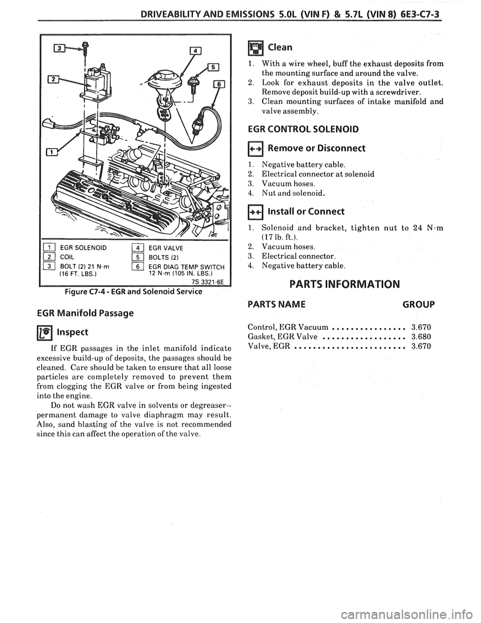
EGR SOLENOID 1 EGR VALVE
121 COIL 151 BOLTS (2)
ls] BOLT (2) 21 N.m EGR DlAG TEMP SWITCH
(16 FT. LBS.) 12 N.m (105
IN. LBS.)
Figure C7-4 - EGR and Solenoid Service
EGR Manifold Passage
Inspect
If EGR passages in the inlet manifold indicate
excessive build-up of deposits, the passages should be
cleaned. Care should be taken to ensure that all loose
particles are completely removed to prevent them
from clogging the EGR valve or from being ingested
into the engine.
Do not wash EGR valve in solvents or degreaser--
permanent damage to valve diaphragm may result.
Also, sand blasting of the valve is not recommended
since this can affect the operation of the valve.
EGR CONTROL SOLENOID
Remove or Disconnect
1. Negative battery cable.
2. Electrical connector at solenoid
3. Vacuum hoses.
4. Nut and solenoid.
Install or Connect
1. Solenoid and bracket, tighten nut to 24 N-m
(17 1b. ft.).
2. Vacuum hoses.
3. Electrical connector.
4. Negative battery cable.
PARTS INFORMATION
PARTS NAME GROUP
Control, EGR Vacuum ................ 3.670
Gasket, EGR Valve .................. 3.680
Valve, EGR ........................ 3.670
Page 1108 of 1825
AUTOMATIC TRANSMISSION 700-R4-57
If:
e
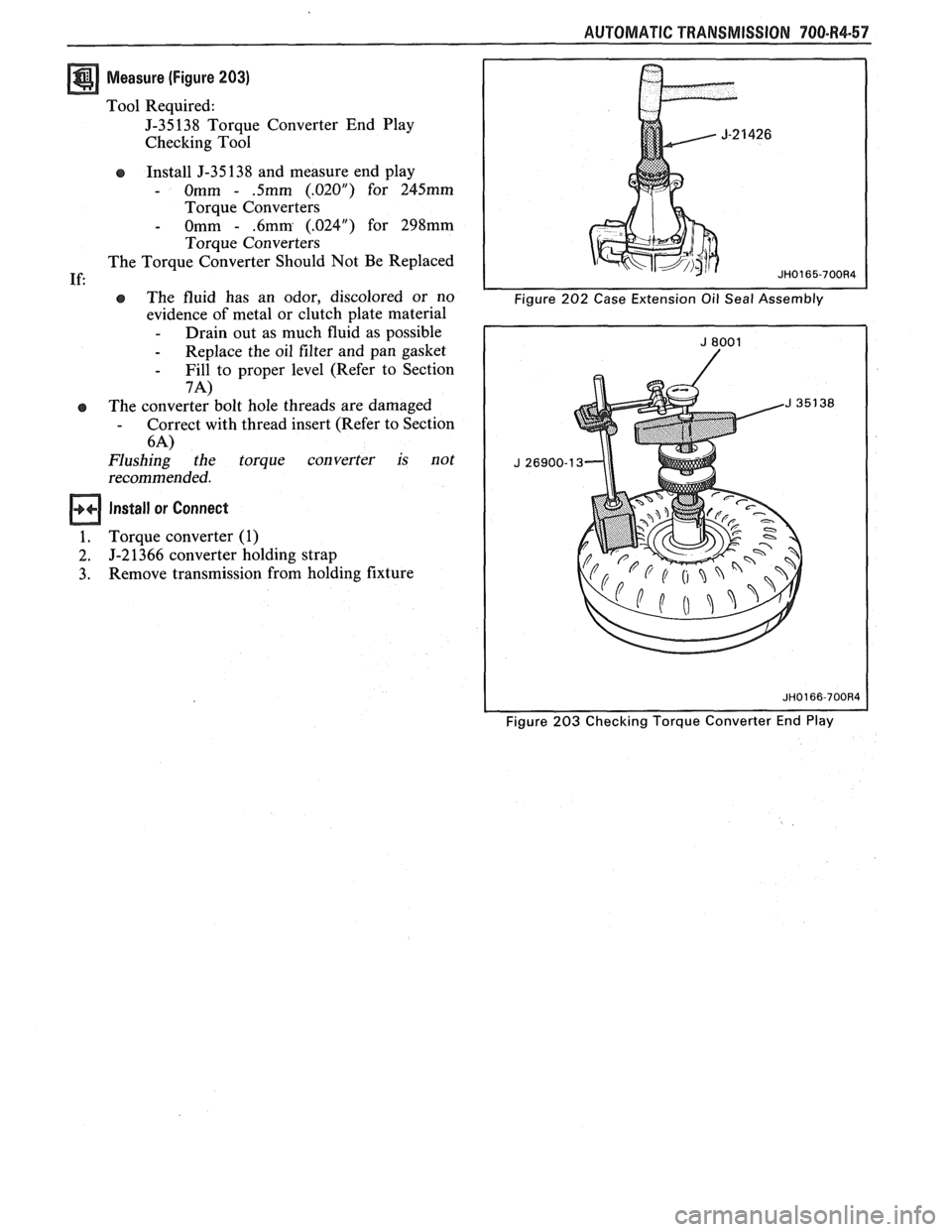
Measure (Figure 203)
Tool Required:
J-35138 Torque Converter End Play
Checking Tool
Install J-35 138 and measure end play
- Omm - .5mm (.02OU) for 245mm
Torque Converters
- Omm - .6mm (.024") for 298mm
Torque Converters
The Torque Converter Should Not Be Replaced
e The fluid has an odor, discolored or no
evidence of metal or clutch plate material
- Drain out as much fluid as possible
- Replace the oil filter and pan gasket
- Fill to proper level (Refer to Section
7A)
The converter bolt hole threads are damaged - Correct with thread insert (Refer to Section
6-4)
Flushing the torque converter is not
recommended.
Install or Connect
Torque converter (1)
J-2 1366 converter holding strap
Remove transmission from holding fixture
Figure 203 Checking Torque Converter End Play
Page 1665 of 1825
98-2 CRUISE CONTROL
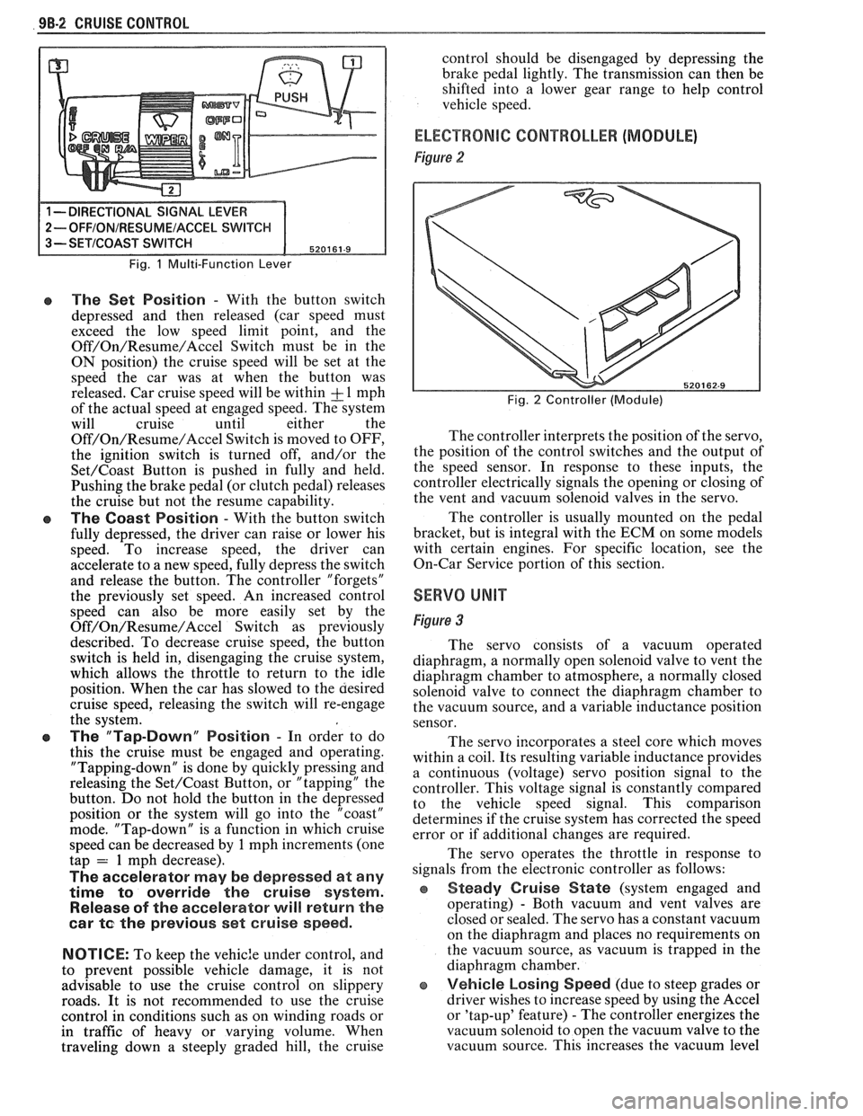
Fig. 1 Multi-Function Lever
e The Set Position - With the button switch
depressed and then released (car speed must
exceed the low speed limit point, and the
Off/On/Resume/Accel Switch must be in the
ON position) the cruise speed will be set at the
speed the car was at when the button was
released. Car cruise speed will be within
& 1 mph
of the actual speed at engaged speed. The system
will cruise until either the
Off/On/Resume/Accel Switch is moved to OFF,
the ignition switch is turned off, and/or the
Set/Coast Button is pushed in fully and held.
Pushing the brake pedal (or clutch pedal) releases
the cruise but not the resume capability.
The Coast Position - With the button switch
fully depressed, the driver can raise or lower his
speed. To increase speed, the driver can
accelerate to a new speed, fully depress the switch
and release the button. The controller "forgets"
the previously set speed. An increased control
speed can also be more easily set by the
Off/On/Resume/Accel Switch as previously
described. To decrease cruise speed, the button
switch is held in, disengaging the cruise system,
which allows the throttle to return to the idle
position. When the car has slowed to the aesired
cruise speed, releasing the switch will re-engage
the system.
e The "Tap-Down" Position - In order to do
this the cruise must be engaged and operating.
"Tapping-down" is done by quickly pressing and
releasing the
Set/Coast Button, or "tapping" the
button. Do not hold the button in the depressed
position or the system will go into the "coast"
mode. "Tap-down" is a function in which cruise
speed can be decreased by
1 mph increments (one
tap = 1 mph decrease).
The accelerator may be depressed at any
time
to override the cruise system.
Release of the accelerator will return the
car
te the previous set cruise speed.
NOTICE:
To keep the vehic:e under control, and
to prevent possible vehicle damage, it is not
advisable to use the cruise control on slippery
roads. It is not recommended to use the cruise
control in conditions such as on winding roads or
in traffic of heavy or varying volume. When
traveling down
a steeply graded hill, the cruise control
should be disengaged by depressing the
bralte pedal lightly. The transmission can then be
shifted into a lower gear range to help control
vehicle speed.
ELECTRONIC CONTROLLER (MODULE)
Figure 2
Fig. 2 Controller (Module)
The controller interprets the position of the servo,
the position of the control switches and the output of
the speed sensor. In response to these inputs, the
controller electrically signals the opening or closing of
the vent and vacuum solenoid valves in the servo.
The controller is usually mounted on the pedal
bracket, but is integral with the ECM on some models
with certain engines. For specific location, see the
On-Car Service portion of this section.
SERVO UNIT
Figure 3
The servo consists of a vacuum operated
diaphragm, a normally open solenoid valve to vent the
diaphragm chamber to atmosphere, a normally closed
solenoid valve to connect the diaphragm chamber to
the vacuum source, and a variable inductance position
sensor.
The servo incorporates a steel core which moves
within a coil. Its resulting variable inductance provides
a continuous (voltage) servo position signal to the
controller. This voltage signal is constantly compared
to the vehicle speed signal. This comparison
determines if the cruise system has corrected the speed
error or if additional changes are required.
The servo operates the throttle in response to
signals from the electronic controller as follows:
Steady Cruise State (system engaged and
operating)
- Both vacuum and vent valves are
closed or sealed. The servo has a constant vacuum
on the diaphragm and places no requirements on
the vacuum source, as vacuum is trapped in the
diaphragm chamber.
e Vehicle Losing Speed (due to steep grades or
driver wishes to increase speed by using the Accel
or 'tap-up' feature)
- The controller energizes the
vacuum solenoid to open the vacuum valve to the
vacuum source. This increases the vacuum level
Page 1683 of 1825
1 H-2 GENERAL INFORMATION - F STYLE
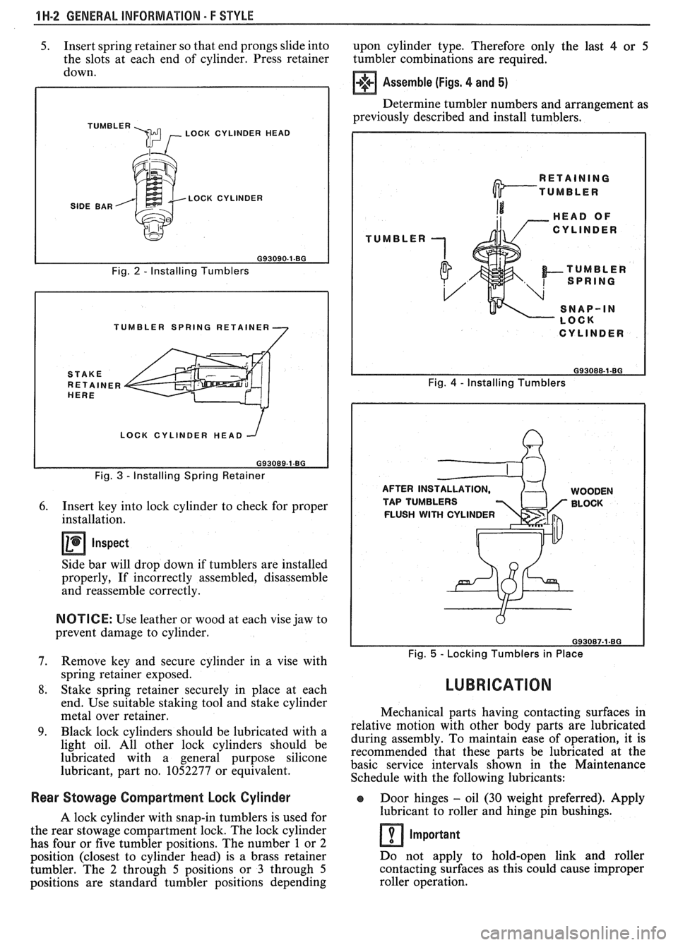
5. Insert spring retainer so that end prongs slide into
upon cylinder type. Therefore only the last 4 or 5
the slots at each end of cylinder. Press retainer
tumbler combinations are required.
down.
TUMBLER \m , LOCK CYLINDER HEAD
SIDE BAR LOCK CYLINDER
Fig.
2 - Installing Tumblers
TUMBLER SPRING RETAINER
LOCK CYLINDER HEAD
Fig.
3 - Installing Spring Retainer
6. Insert key into lock cylinder to check for proper
installation.
Inspect
Side bar will drop down if tumblers are installed
properly, If incorrectly assembled, disassemble
and reassemble correctly.
NOTICE: Use leather or wood at each vise jaw to
prevent damage to cylinder.
7. Remove key and secure cylinder in a vise with
spring retainer exposed.
8. Stake spring retainer securely in place at each
end. Use suitable staking tool and stake cylinder
metal over retainer.
9. Black lock cylinders should be lubricated with a
light oil. All other lock cylinders should be
lubricated with a general purpose silicone
lubricant, part no. 1052277 or equivalent.
Assemble (Figs. 4 and 5)
Determine tumbler numbers and arrangement as
previously described and install tumblers,
TUMBLER
I CYLINDER I
Fig. 4 - Installing Tumblers
AFTER INS WOODEN
TAP TUMBLERS BLOCK
FLUSH
WITH CYLINDER
Fig. 5 - Locking Tumblers in Place
LUBRICATION
Mechanical parts having contacting surfaces in
relative motion with other body parts are lubricated
during assembly. To maintain ease of operation, it is
recommended that these parts be lubricated at the
basic service intervals shown in the Maintenance
Schedule with the following lubricants:
Rear Stowage Compartment Lock Cylinder Door hinges - oil (30 weight preferred). Apply
A lock cylinder with snap-in tumblers is used for lubricant
to roller and hinge pin bushings.
the rear stowage compartment lock. The lock cylinder
Important has four or five tumbler positions. The number 1 or 2
position (closest to cylinder head) is a brass retainer Do
not apply to hold-open link and roller
tumbler. The
2 through 5 positions or 3 through 5 contacting
surfaces as this could cause improper
positions are standard tumbler positions depending roller operation.
Page 1745 of 1825
71.1-2 REAR END - F STYLE
dampened slightly with oil-free naphtha;
then remove tape strips.
COMPARTMENT LIFT WINDOW MOLDING
Refinishing
1. Mask off area(s) adjacent to molding(s).
2. Clean with Ditzler's DX-440 wax and grease
removing solvent or equivalent.
3. Sand with
#400 grit wet or dry sandpaper.
4. Clean
with wax and grease removing solvent.
5. Prime with Ditzler's
epoxy chromate primer DP
40/40 1 or equivalent.
6. Sand with
#500 grit wet or dry sandpaper.
7. Clean with wax and grease removing solvent.
8. Top
coat with flat black acrylic lacquer.
9. Remove masking tape.
When using any of the listed materials, follow the
manufacturer's label directions for application
procedures and drying time.
Removal
CAUTION: When working with glass
assemblies, the use of personal
protection items such as safety
glasses and work gloves is
recommended to minimize the chance
of personal injury should the glass
break.
1. Remove compartment lift window from body, as
described later in this section, and with the aid of
a helper, place upside down on a protected work
surface.
2. Remove upper hinges.
3. Remove screws retaining moldings to panel.
CAUTION: Perform the urethane
burn-out operation in a well ventilated
area and avoid direct inhalation of the
fumes being emitted as these fumes
may be hazardous.
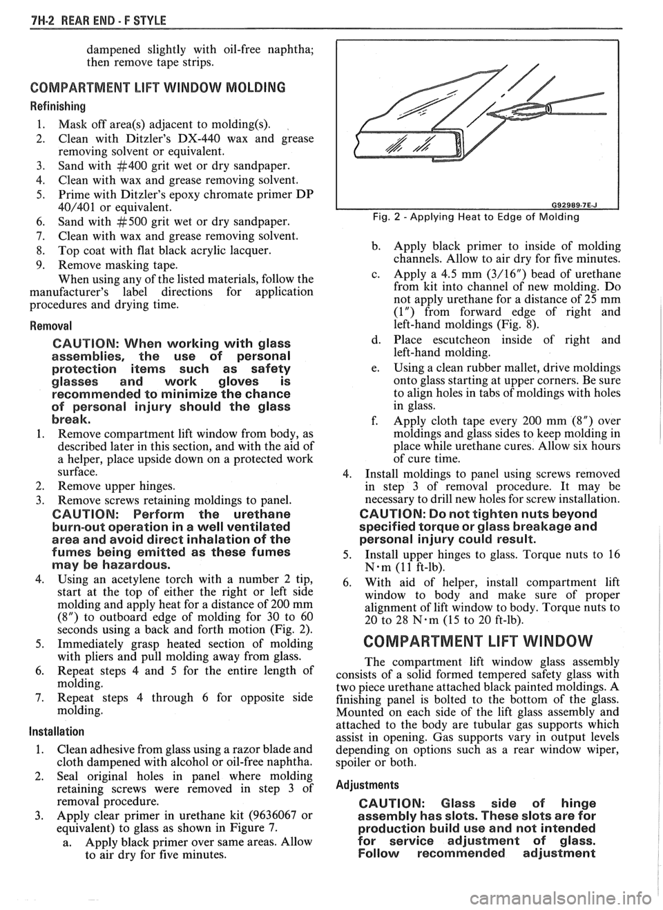
4. Using an acetylene torch with a number 2 tip,
start at the top of either the right or left side
molding and apply heat for a distance of 200 mm
(8") to outboard edge of molding for 30 to 60
seconds using a back and forth motion (Fig. 2).
5. Immediately grasp heated section of molding
with pliers and pull molding away from glass.
6. Repeat steps
4 and 5 for the entire length of
molding.
7. Repeat steps 4 through 6 for opposite side
molding.
Installation
1. Clean adhesive from glass using a razor blade and
cloth dampened with alcohol or oil-free naphtha.
2. Seal original holes in panel where molding
retaining screws were removed in step 3 of
removal procedure.
3. Apply clear primer in urethane kit (9636067 or
equivalent) to glass as shown in Figure 7.
a. Apply
black primer over same areas. Allow
to air dry for five minutes.
Fig. 2 -Applying Heat to Edge of Molding
b. Apply
black primer to inside of molding
channels. Allow to air dry for five minutes.
c. Apply a 4.5 mm
(3/16") bead of urethane
from kit into channel of new molding. Do
not apply urethane for a distance of
25 mm
(1") from forward edge of right and
left-hand moldings (Fig. 8).
d. Place escutcheon inside of right and
left-hand molding.
e. Using a
clean rubber mallet, drive moldings
onto glass starting at upper corners. Be sure
to align holes in tabs of moldings with holes
in glass.
f. Apply cloth tape every 200 mm (8") over
moldings and glass sides to keep molding in
place while urethane cures. Allow six hours
of cure time.
4. Install moldings to panel using screws removed
in step 3 of removal procedure. It may be
necessary to drill new holes for screw installation.
CAUTION: Do not tighten nuts beyond
specified torque or glass breakage and
personal injury could result.
5. Install
upper hinges to glass. Torque nuts to 16
N-m (1 1 ft-lb).
6. With aid of helper, install compartment lift
window to body and make sure of proper
alignment of lift window to body. Torque nuts to
20 to 28
N-m (15 to 20 ft-lb).
COMPARTMENT LIFT WINDOW
The compartment lift window glass assembly
consists of a solid formed tempered safety glass with
two piece urethane attached black painted moldings. A
finishing panel is bolted to the bottom of the glass.
Mounted on each side of the lift glass assembly and
attached to the body are tubular gas supports which
assist in opening. Gas supports vary in output levels
depending on options such as a rear window wiper,
spoiler or both.
Adjustments
CAUTION: Glass side of hinge
assembly has slots. These slots are for
production build use and not intended
for service adjustment of
glass.
Follow recommended adjustment
Page 1758 of 1825
WEAR END - F STYLE 7H-15
A
SECTION A-A 1. SPOILER
2. PLUG
3. NUT
4. WASHER
6. STUD 093858-7H.F
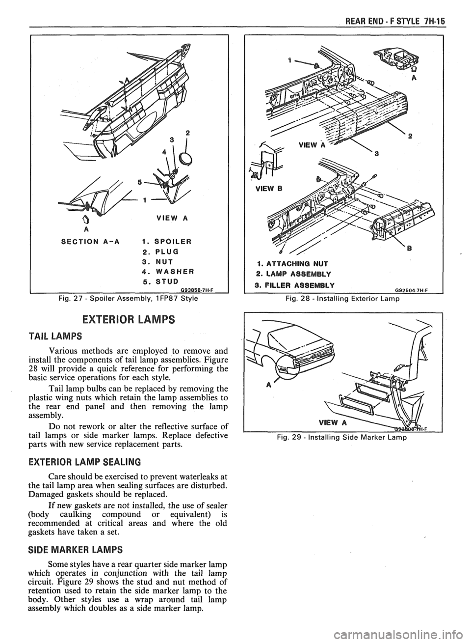
Fig. 27 - Spoiler Assembly, 1 FP87 Style
1. ATTACHING NUT
2. LAMP A98EMBLY
Fig. 28 - Installing Exterior Lamp
EXTERIOR LAMPS
TAIL LAMPS
Various methods are employed to remove and
install the components of tail lamp assemblies. Figure
28 will provide a quick reference for performing the
basic service operations for each style.
Tail lamp bulbs can be replaced by removing the
plastic wing nuts which retain the lamp assemblies to
the rear end panel and then removing the lamp
assembly.
Do not rework or alter the reflective surface of
tail lamps or side marker lamps. Replace defective
Fig. 29 - Installing Side Marker Lamp parts with new service replacement parts.
EXTERIOR LAMP SEALING
Care should be exercised to prevent waterleaks at
the tail lamp area when sealing surfaces are disturbed.
Damaged gaskets should be replaced.
If new gaskets are not installed, the use
of sealer
(body caulking compound or equivalent) is
recommended at critical areas and where the old
gaskets have taken a set.
SIDE MARKER LAMPS
Some styles have a rear quarter side marker lamp
which operates in conjunction with the tail lamp
circuit. Figure
29 shows the stud and nut method of
retention used to retain the side marker lamp to the
body. Other styles use a wrap around tail lamp
assembly which doubles as a side marker lamp.