cruise control PONTIAC FIERO 1988 Service Repair Manual
[x] Cancel search | Manufacturer: PONTIAC, Model Year: 1988, Model line: FIERO, Model: PONTIAC FIERO 1988Pages: 1825, PDF Size: 99.44 MB
Page 2 of 1825
1988
SER
This manual applies to the 1988 Pontiac Firebird Models.
It contains the latest product information available at the
time of publication approval. lnformation pertaining to
the operation of the vehicle is contained in the Owner's
Manual which accompanies each vehicle. The right is
reserved to make changes at any time without notice.
Any references to brand names in this manual is intended
merely as an example of the types of
lubricant% tools,
materials, etc, recommended for use in servicing 1988
Pontiac Models. In all cases, an equivalent may be used.
PONTIAC DIVISION
GENERAL
MOTORS CORPORATION
PONTIAC, MICHIGAN 48053
1987 General Motors Corp. All Rights Reserved.
No part of this publication may be reproduced, stored in any
retrieval system or transmitted in any form or by any means,
including but not limited to electronic, mechanical,
photocopying, recording or otherwise, without the prior written
permission of General Motors Corp. This includes all text,
illustrations, tables and charts.
S-881 OF 9-87 Printed in Canada
TABLE OF CONTENTS
SECTION NAME
GENERAL INFORMATION
OA. General lnformation
OB. Maintenance & Lubrication
1 SECT.
HEATING AND AIR CONDITIONING
1A. Heating and Ventilation
1 B. Air Conditioning
1D1. R-4 AIC Com~ressor Overhaul
FRAME AND BUMPERS
2B. Bumpers 2C. Chassis Sheet Metal
STEERING, SUSPENSION, WHEELS
AND TIRES
3. Diagnosis
3A. Wheel Alignment
3B5. Steering Wheels and Columns 3B6. Steering Linkage 3B7. Power Steering Gear and Pump
3C. Front Suspension
3D. Rear Suspension
3E. Tires and Wheels
FINAL DRIVE
4A. Propeller Shaft
4B. Rear Axle
4B1. Bora-Warner Axle
BRAKES 5. Brakes 5A3. Comoosite Master Cvlinder 5B1. Disc r rake Caliper ~ssembly - 300013100 Series 5B6. Disc Brake Caliper Assembly - 3548
Series
5C3. Direct Torque Drum Brake Assembly 5D2. Power Head Assembly - Tandem Diaohraam 5F. ~~ecifications and Special Tools
ENGINE 6. Engine General lnformation 6A2. 2.8L 6A3. 5.OL & 5.7L 6B. Engine Cooling
6C. En~ine Fuel
6D. ~ngine Electrical 6D1. Battery 6D2. Cranking System 6D3. Charging System 6D4. Ignition System 6D5. Engine Wiring
6E. Driveabilitv and Emissions
6E2. ~missions' 6E3. Emissions - PFI
6F. Engine Exhaust
TRANSMISSION 7A. Automatic Transmission - General
lnformation
7A1. Automatic Transmission - On-Car
Service
700R4. Automatic Transmission Hydraulic Diagnosis
700R4. Automatic Transmission Unit Repair
76. 5-Speed Manual Transmission
7C. Clutch
CHASSIS ELECTRICAL 8A. Electrical Diagnosis
8B. Lighting and Horns
8C. Instrument
Panel, Gages
& Console
8E. Windshield Wiper &Washer System
ACCESSORIES 9A. Radio Systems and Antennas 9B. Cruise Control 9G. Miscellaneous Accessories
I BODY SERVICE MANUAL END
OF
MANUAL
Page 173 of 1825
385-22 STEERING WHEELS AND COLUMNS
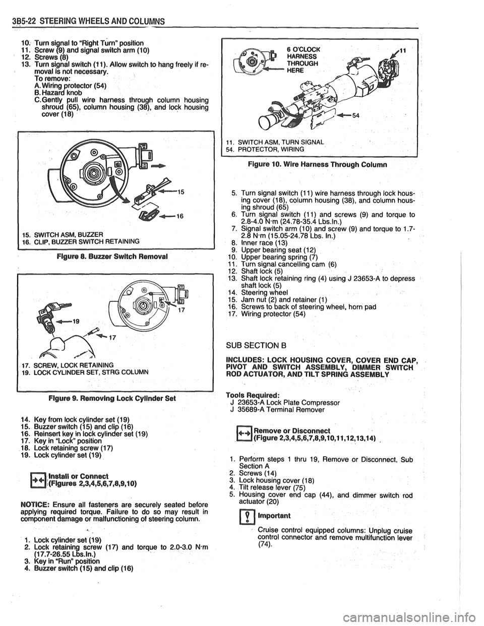
10. Turn si nal to "Right Turnn position 11. Screw f9) and signal switch arm (10) 12. crews (8) 13. Turn signal switch (11). Allow switch to hang freely if re- moval is not necessary.
To remove:
A. Wiring protector (54) B. Hanard knob C.Gently pull wire harness through column housing
shroud (65), column housing (38), and lock housing
cover (1 8)
5. Turn signal switch (I 1) wire harness through lock hous-
ing cover (18), column housing (38), and column hous-
ing shroud (65)
6. Turn signal switch (1 1) and screws (9) and torque to
2.8-4.0
N.m (24.78-35.4 Lbs.ln.) 7. Signal switch arm (10) and screw (9) and torque to 1.7- 2.8 N.m (1 5.05-24.78 Lbs. In.)
8. Inner race (13)
9. Upper bearing seat (12)
10. Upper bearing spring (7)
11. Turn signal cancelling cam (6)
12. Shaft lock (5)
13. Shaft lock retaining ring (4) using J 23653-A to depress
shaft lock (5)
14. Steering wheel
15. Jam nut (2) and retainer
(1) 16. Screws to back of steering wheel, horn pad
17. Wiring protector (54)
SUB SECTION 6
17. SCREW, LOCK RETAINING INCLUDES:
LOCK HOUSING COVER, COVER END CAP, 19. LOCK CYLINDER SET, STRG COLUMN PIVOT
AND SWITCH ASSEMBLY, DIMMER SWITCH
ROD ACTUATOR, AND TILT SPRING ASSEMBLY
Flgurs 9. Rsmovlng Lock Cylinder Set Tools
Required:
J 23653-A Lock Plate Compressor
J 35689-A Terminal Remover
14. Key from lock cylinder set (19)
15.
Buuer switch (1 5) and clip (1 6)
16. Reinsert key in lock cylinder set (1 9) Remove
or Disconnect
17. Key in "Lock" position
m(Flgure 2,3,4,5,6,7,8,9,10,11,12,13,14) -
18. Lock retaining screw (1 7) 19. Lock cylinder set (1 9) 1. Perform steps 1 thru 19, Remove or Disconnect, Sub
Section A
lnsbll or Connect 2.
Screws (14)
m~(FIguns 2,3,4,56,7,(1,9,10) 3. Lock housing cover (1 8)
4. Tilt release lever (75)
5. Housing cover end cap
(44), and dimmer switch rod
NOTICE: Ensure all fasteners are securely seated before actuator (20)
applying required torque. Failure to do so may result in
component damage or malfunctioning of steering column.
lmporlant
Cruise control equipped columns: Unplug cruise
1. Lock cylinder set
(1 9) control
connector and remove multifunction lever 2. Lock retainin screw (17) and torque to 2.0-3.0 N-m (74).
(1 7.7-2~55 ~!s.ln.) 3. Key in "Runn position 4. Buner switch (1 5) and clip (1 6)
Page 174 of 1825
STEERING WHEELS AND COLUMNS 385.23
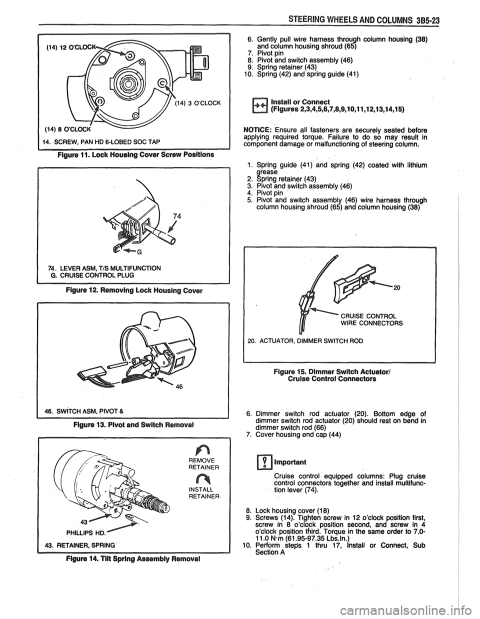
Figure 11. Lock Housing Cover Screw Positions
74. LEVER ASM, TIS MULTIFUNCTION I G. CRUISE CONTROL PLUG
Figure 12. Removing Lock Housing Cover
1 46. SWITCH ASM, PIVOT 81
Figure 13. Pivot and Switch Removal
REMOVE
RETAINER
n INSTALL
RETAINER
Flgum 14. Tilt Spring Aessmbly Removal
6. Gently pull wire harness throu h column housing (38)
and column housing shroud (657 7. Pivot pin 8. Pivot and switch assembly (46)
9. Spring retainer (43)
10. Spring (42) and spring guide (41)
Install or Connect
(Figures 2,3,4,5,6,7,8,9,10,11 ,12,13,14,1 5)
NOTICE: Ensure all fasteners are securely seated before
applying required torque. Failure to do so may result in
component damage or malfunctioning of steering column.
1. Spring guide (41) and spring (42) coated with lithium
2. !$;rK: retainer (43) 3. Pivot and switch assembly (46)
4. Pivot pin
5. Pivot and switch assembly (46) wire harness through
column housing shroud (65) and column housing (38)
CRUISE CONTROL WIRE CONNECTORS
Figure 15. Dimmer Switch Actuator1 Cruise Control Connectors
6. Dimmer switch rod actuator (20). Bottom edge of
dimmer switch rod actuator (20) should rest on bend in
dimmer switch rod (66)
7. Cover housing end cap (44)
important
Cruise control equipped columns: Plug cruise
control connectors together and install multifunc-
tion lever
(74).
8. Lock housing cover (18)
9. Screws (14). Tighten screw in 12 o'clock position first,
screw in 8 o'clock position second, and screw in 4
o'clock position third. Torque in the same order to
7.0- 11 .O N.m (61.95-97.35 Lbs.ln.) 10. Perform step's 1 thru 17, install or Connect, Sub
Section A
Page 181 of 1825
385-30 STEERING WHEELS AND COLUMNS
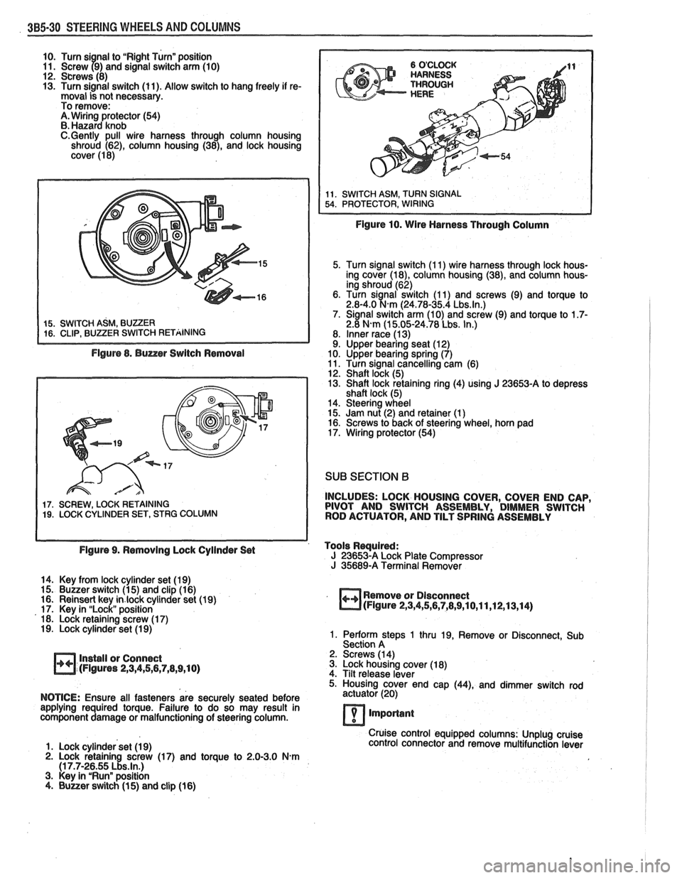
10. Turn si nal to "Right Turn" position
11. Screw 79) and signal switch arm (10)
12. Screws (8)
13. Turn signal switch (11). Allow switch to hang freely if re-
moval is not necessary.
To remove:
A. Wiring protector (54)
B. Hazard knob
C.Gently pull wire harness through column housing
shroud (62), column housing (38), and lock housing
cover (1 8)
Figure 8. Buzzer Switch Removal
17. SCREW, LOCK RETAINING 19. LOCK CYLINDER SET, STRG COLUMN
Figure 10. Wire Harness Through Column
5. Turn signal switch (1 1) wire harness through lock hous-
ing cover
(la), column housing (38), and column hous-
ing shroud (62)
6. Turn
sianal switch (1 1) and screws (9) and torque to 2.8-4.0 %km (24.78-35.4 Lbs.ln.) 7. Signal switch arm (10) and screw (9) and torque to 1.7- 2.8 N-m (1 5.05-24.78 Lbs. In.)
8. Inner race (1 3) 9. Upper bearing seat (1 2)
10. Upper bearing spring (7)
11. Turn signal cancelling cam (6)
12. Shaft lock (5)
13. Shaft lock retaining ring (4) using
J 23653-A to depress
shaft lock (5)
14. Steering wheel
15. Jam nut (2) and retainer (1
) 16. Screws to back of steering wheel, horn pad
17. Wiring protector (54)
SUB SECTION B
INCLUDES: LOCK HOUSING COVER, COVER END CAP,
PIVOT AND SWITCH ASSEMBLY, DIMMER SWITCH
ROD ACTUATOR, AND TILT SPRING ASSEMBLY
Figure 9. Removing Lock Cyilnder Set Tools
Rwuired: J 23653-A Lock
Plate Compressor J 35689-A Terminal Remover
14. Key from lock cylinder set (19)
15. Buzzer switch (1 5) and clip (1 6)
16. Reinsert key
in.lock cylinder set (19)
17. Key in "Lock" position
18. Lock retaining screw (1 7)
19. Lock cylinder set (1 9)
Install or Connect
(Figures
2,3,4,5,6,7,8,9,10)
Remove or Dlsconnect (Figure 2,3,4,5,6,7,8,9,10,11,12,13,14)
1. Perform steps 1 thru 19, Remove or Disconnect, Sub
Section A
2. Screws (1 4)
3. Lock housing cover (1 8)
4. Tilt release lever
5. Housing cover end cap
(44), and dimmer switch rod
NOTICE: Ensure all fasteners are securely seated before actuator
(20)
applying required torque. Failure to do so may result in
component damage or malfunctioning of steering column.
7 important
Cruise control equipped columns: Unplug cruise
1. Lock cylinder set (1 9) control
connector and remove multifunction lever
2. Lock retaining screw (17) and torque to 2.0-3.0 N.m (1 7.7-26.55 Lbs.ln.) 3. Key in "Run" position
4. Buuer switch (1 5) and clip (16)
Page 182 of 1825
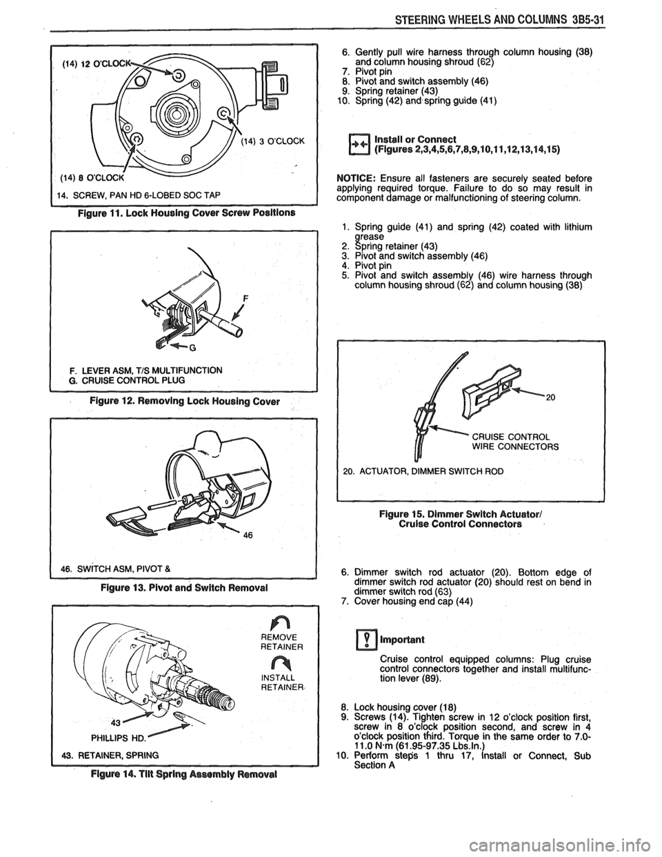
STEERING WHEELS AND COLUMNS 385-31
Figure 11. Lock Housing Cover Screw Positions
F. LEVER ASM, TIS MULTIFUNCTION
Figure 12. Removing Lock Housing Cover
6. Gently pull wire harness through column housing (38)
and column housing shroud (62)
7. Pivot pin
8. Pivot and switch assembly (46)
9. Spring retainer (43)
10. Spring (42) and spring guide
(41)
Install or Connect
(Figures 2,3,4,5,6,7,8,9,10,11,12,13,14,15)
NOTICE: Ensure all fasteners are securely seated before
applying required torque. Failure to do so may result in
component damage or malfunctioning of steering column.
1. Spring guide (41) and spring (42) coated with lithium
rease
2. gpring retainer (43)
3. Pivot and switch assembly (46) 4. Pivot pin 5. Pivot and switch assembly (46) wire harness through
column housing shroud (62) and column housing (38)
CRUISE CONTROL WIRE CONNECTORS
6. Dimmer switch rod actuator (20). Bottom edge of
dimmer switch rod actuator (20) should rest on bend in
dimmer switch rod (63)
7. Cover housing end cap (44)
1 43. RETAINER, SPRING REMOVE
RETAINER
INSTALL
RETAINER.
Figure 14. Tlit Sprlng Aswmbly ~emovel
Cruise control equipped columns: Plug cruise
control connectors together and install multifunc-
tion lever (89).
8. Lock housing cover (1
8) 9. Screws (14). Tighten screw in 12 o'clock position first,
screw in 8 o'clock position second, and screw in 4
o'clock position third. Torque in the same order to
7.0- 11 .O N.m (61.95-97.35 Lbs.ln.) 10. Periorrn steps 1 thru 17, Install or Connect, Sub
Section A
Page 301 of 1825
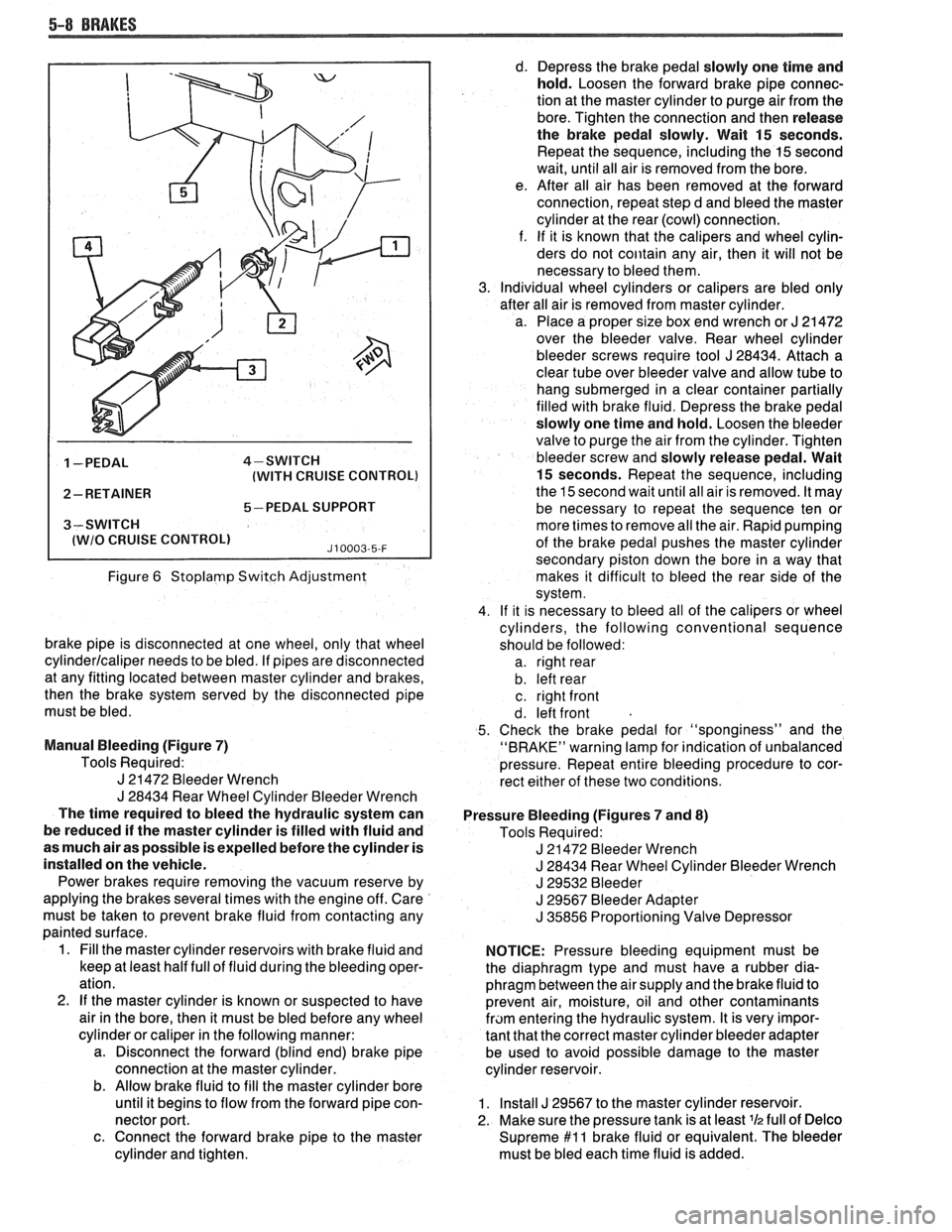
5-8 BRAKES
1 -PEDAL 4-SWITCH
(WITH CRUISE CONTROL)
2- RETAINER
5-PEDAL SUPPORT
3-SWITCH
I lWlO CRUISE CONTROLl J10003-5-F
Figure 6 Stoplamp Switch Adjustment
brake pipe is disconnected at one wheel, only that wheel
cylinderlcaliper needs to be bled. If pipes are disconnected
at any fitting located between master cylinder and brakes,
then the brake system served by the disconnected pipe
must be bled.
Manual Bleeding (Figure
7)
Tools Required:
J 21472 Bleeder Wrench
J 28434 Rear Wheel Cylinder Bleeder Wrench
The time required to bleed the hydraulic system can
be reduced if the master cylinder is filled with fluid and
as much air as possible is expelled before the cylinder is
installed on the vehicle.
Power brakes require removing the vacuum reserve by
applying the brakes several times with the engine off. Care
must be taken to prevent brake fluid from contacting any
painted surface.
1. Fill the master cylinder reservoirs with brake fluid and
keep at least half full of fluid during the bleeding oper-
ation.
2.
If the master cylinder is known or suspected to have
air in the bore, then it must be bled before any wheel
cylinder or caliper in the following manner:
a. Disconnect the forward (blind end) brake pipe
connection at the master cylinder.
b. Allow brake fluid to fill the master cylinder bore
until it begins to flow from the forward pipe con-
nector port.
c. Connect the forward brake pipe to the master
cylinder and tighten. d.
Depress the brake pedal slowly one time and
hold. Loosen the forward brake pipe connec-
tion at the master cylinder to purge air from the
bore. Tighten the connection and then release
the brake pedal slowly. Wait
15 seconds.
Repeat the sequence, including the
15 second
wait, until all air is removed from the bore.
e. After all air has been removed at the forward
connection, repeat step d and bleed the master
cylinder at the rear (cowl) connection.
f. If it is known that the calipers and wheel cylin-
ders do not
coiitain any air, then it will not be
necessary to bleed them.
Individual wheel cylinders or calipers are bled only
after all air is removed from master cylinder.
a. Place a proper size box end wrench or
J 21 472
over the bleeder valve. Rear wheel cylinder
bleeder screws require tool
J 28434. Attach a
clear tube over bleeder valve and allow tube to
hang submerged in a clear container partially
filled with brake fluid. Depress the brake pedal
slowly one time and hold. Loosen the bleeder
valve to purge the air from the cylinder. Tighten
bleeder screw and slowly release pedal. Wait
15 seconds. Repeat the sequence, including
the 15 second wait until all air is removed. It may
be necessary to repeat the sequence ten or
more times to remove all the air. Rapid pumping
of the brake pedal pushes the master cylinder
secondary piston down the bore in a way that
makes it difficult to bleed the rear side of the
system.
If it is necessary to bleed all of the calipers or wheel
cylinders, the following conventional sequence
should be followed: a. right rear
b. left rear
c. right front
d. left front
Check the brake pedal for "sponginess" and the
"BRAKE" warning lamp for indication of unbalanced
pressure. Repeat entire bleeding procedure to cor-
rect either of these two conditions.
Pressure Bleeding (Figures
7 and 8)
Tools Required:
J 21472 Bleeder Wrench
J 28434 Rear Wheel Cylinder Bleeder Wrench
J 29532 Bleeder
J 29567 Bleeder Adapter
J 35856 Proportioning Valve Depressor
NOTICE: Pressure bleeding equipment must be
the diaphragm type and must have a rubber dia-
phragm between the air supply and the brake fluid to
prevent air, moisture, oil and other contaminants
fram entering the hydraulic system. It is very impor-
tant that the correct master cylinder bleeder adapter
be used to avoid possible damage to the master
cylinder reservoir.
1. Install J 29567 to the master cylinder reservoir.
2. Make sure the pressure tank is at least
lh full of Delco
Supreme $1 1 brake fluid or equivalent. The bleeder
must be bled each time fluid is added.
Page 376 of 1825
2.8 LITER V-6 6A2-25
Fitting
1. Select rings comparable in size to the piston being
used.
2. Slip
the compression ring in the cylinder bore;
then press the ring down into the cylinder bore
about 6mm above ring travel. Be sure ring is
square with cylinder wall.
3. Measure the space or gap between the ends of the
ring with a feeler gage (Figure
6A2-33).
4. If
the gap between the ends of the ring is below
specifications, remove the ring and try another
for fit.
5. Fit each compression ring to the cylinder in
which it is going to be used.
6. If the pistons have not been cleaned and inspected
as previously outlined, do so.
7. Slip the outer surface of the top and second
compression ring into the respective piston ring
groove and roll the ring entirely around the
groove (Figure
6A2-34). If binding occurs at any
point, the cause should be determined. If there is
a ring groove, remove by dressing with a fine cut
file. If the binding is caused by a distorted ring,
check a new ring.
Installation
1. Install oil ring spacer in groove being sure ends
are butted and not overlapped.
2. Hold
spacer ends butted and install lower steel oil
ring rail.
3. Install upper
steel oil ring rail with gap staggered.
4. Flex
the oil ring assembly to make sure ring is
free. If binding occurs, the cause should be
detemined. If caused by ring groove, remove by
dressing groove with a fine cut file. If binding is
caused by a distorted ring, check a new ring.
5. Install second compression ring. Stagger gap
from other rings.
6. Install top compression ring with gap properly
located.
ENGINE ASSEMBLY
Removal
Disconnect battery.
Remove air cleaner.
Remove hood. Drain radiator.
Remove lower radiator hose.
Remove upper fan shroud.
Remove upper radiator hose and coolant
recovery hose.
Remove transmission cooler lines. Remove radiator.
Remove fan assembly.
Remove heater hoses.
Disconnect carburetor linkage, includes cruise
control detent cable.
Remove vacuum brake booster line.
Remove distributor cap and lay wiring aside.
Disconnect necessary wires and hoses.
Remove power steering pump and lay aside. Raise
vehicle.
Remove exhaust pipes at exhaust manifold.
Remove dust cover.
Remove converter bolts.
Disconnect starter wires.
Remove bell housing bolts.
Remove motor mount through bolts.
Disconnect fuel lines at fuel pump.
Lower vehicle. Support transmission.
Remove
A.I.R./Converter pipes bracket.
Remove engine, include removing wire from
bracket at rear left of engine.
Installation
Position engine assembly in vehicle.
Attach motor mount to engine brackets and
lower engine in place.
Remove engine lifting device.
Remove transmission floor jack.
Raise vehicle on hoist.
Install mount "through" bolts. Torque to
specifications.
Install bell housing bolts. Torque to
specifications.
On vehicles with automatic transmission, install
converter to flywheel attaching bolts. Torque to
specifications.
Install flywheel splash shield of conveter housing
cover as applicable. Torque attaching bolts to
specifications.
Install starter wires.
Connect fuel lines.
Connect exhaust pipe at manifold.
Lower vehicle on hoist.
Reinstall power steering pump, if so equipped.
Connect necessary wires and hoses.
Install radiator and fan shroud and reconnect
radiator and heater hoses.
Fill cooling system.
Fill crankcase with oil. See owner's manual for
specifications.
Install air cleaner.
Install hood.
Connect battery cables.
NOTICE: To avoid possible arcing of battery,
connect positive battery cable first.
22. Start engine, check for leaks and check timing.
CRANKSHAFT
The crankshaft can be removed while the engine
is dissasembled for overhaul, as previously outlined or
without complete disassembly.
Removal
1. With the engine removed from the vehicle,
remove the clutch assembly (if equipped) and
flywheel. Mount engine in stand and clamp
securely.
Page 385 of 1825
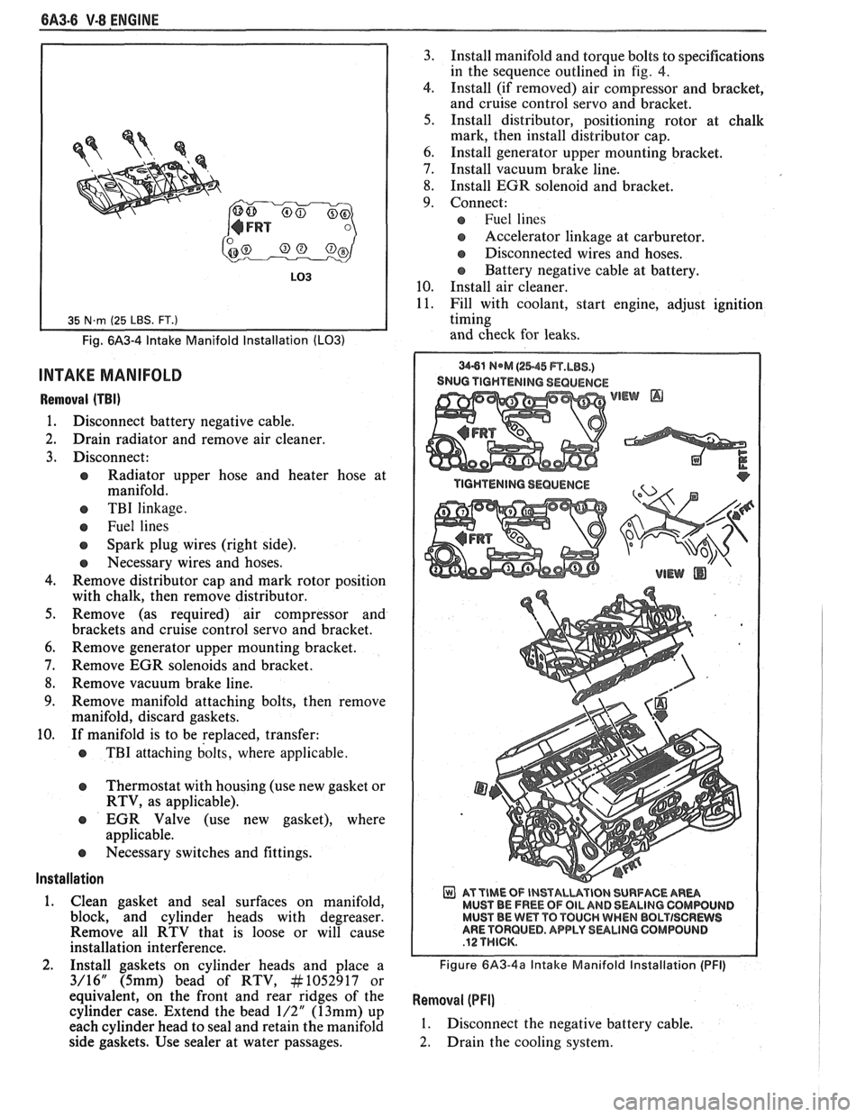
6A3-6 V-8 ENGINE
Fig. 6A3-4 Intake Manifold Installation (LO31
INTAKE MANIFOLD
Removal (TBI)
1. Disconnect battery negative cable.
2. Drain radiator and remove air cleaner.
3. Disconnect:
e Radiator upper hose and heater hose at
manifold.
e TBI linkage.
e Fuel lines
Spark plug wires (right side).
e Necessary wires and hoses.
4. Remove distributor cap and mark rotor position
with chalk, then remove distributor.
5. Remove (as required) air compressor and
brackets and cruise control servo and bracket.
6. Remove generator upper mounting bracket.
7. Remove EGR solenoids and bracket.
8. Remove vacuum brake line.
9. Remove manifold attaching bolts, then remove
manifold, discard gaskets.
10. If manifold is to be replaced, transfer:
e TBI attaching bolts, where applicable.
Thermostat with housing (use new gasket or
RTV, as applicable).
EGR Valve (use new gasket), where
applicable.
e Necessary switches and fittings.
lnstallation
1. Clean gasket and seal surfaces on manifold,
block, and cylinder heads with degreaser.
Remove all RTV that is loose or will cause
installation interference.
2. Install gaskets on cylinder heads and place a
3/16" (5mm) bead of RTV, At1052917 or
equivalent, on the front and rear ridges of the
cylinder case. Extend the bead
1/2" (13mm) up
each cylinder head to seal and retain the manifold
side gaskets. Use sealer at water passages. 3.
Install manifold and torque bolts to specifications
in the sequence outlined in
fig. 4.
4. Install (if removed) air compressor and bracket,
and cruise control servo and bracket.
5. Install distributor, positioning rotor at chalk
mark, then install distributor cap.
6. Install generator upper mounting bracket.
7. Install vacuum brake line.
8. Install EGR solenoid and bracket.
9. Connect:
Fuel lines
s Accelerator linkage at carburetor.
@ Disconnected wires and hoses.
Battery negative cable at battery.
10. Install air cleaner.
11. Fill with coolant, start engine, adjust ignition
timing
and check for leaks.
SNUG TIGHTENING SEQUENCE
WEW @
AT TIME OF INSTALUVIBN SURFACE AR- MUST BE FREE OF OIL AND 8ULlNG CQMWUIJD MUST BE Wm TO TOUCH WHEN BBLTISCRWS ARE TORQUED. APPLY SULINO GOMPOLINB
Figure 6A3-4a Intake Manifold Installation (PFI)
Removal (PFI]
1. Disconnect the negative battery cable.
2. Drain the cooling system.
Page 406 of 1825
V-8 ENGINE 6A3-27
3. When finish honing
a cylinder bore to fit a piston,
the hone should be moved up and down at a
sufficient speed to obtain very fine uniform
surface finish marks in a cross-hatch pattern of
approximately
45" to 65" included angle. The
finish marks should be clean but not sharp, free
from imbedded particles and torn or folded
metal.
4. Permanently mark
the piston for the cylinder to
which it has been fitted and proceed to hone
cylinders and fit the remaining pistons.
NOTICE: Handle the pistons with care and do not
attempt to force them through the cylinder until
the cylinder has been honed to correct size as this
type piston can be distorted through careless
handling.
5. Thoroughly
clean the bores with hot water and
detergent. Scrub well with a stiff bristle brush and
rinse thoroughly with hot water. It is extremely
essential that a good cleaning operation be
performed. If any of the abrasive material is
allowed to remain in the cylinder bores, it will
rapidly wear the new rings and cylinder bores in
addition to the bearings lubricated by the
contaminated oil, the bores should be swabbed
and then wiped with a clean dry cloth. Cylinder
should not be cleaned with kerosene or gasoline.
Clean the remainder of the cylinder block to
remove the excess material spread during the
honing operation.
Piston Selection
1. Check USED piston to cylinder bore clearance as
follows:
a. Measure
the "Cylinder Bore Diameter"
with a telescope gage
"2-1/2" (64mm) from
top of cylinder bore").
b. Measure
the
"Piston Diameter" (at skirt
across center line of piston pin).
c. Subtract
piston diameter from cylinder bore
diameter to determine "Piston to Bore
Clearance".
d. Determine if piston to bore clearance is in
the acceptable range.
2. If
used piston is not acceptable, check Piston Size
Chart and determine if a new piston can be
selected to fit cylinder bore within the acceptable
range.
3. If
cylinder bore must be reconditioned, measure
new piston diameter (across center line of piston
pin) then hone cylinder bore to correct clearance
(preferable range).
4. Mark the piston to identify the cylinder for which
it was fitted.
OIL FILTER BYPASS VALVE
Inspection and Replacement
With the oil filter removed, check the spring and
fibre valve for operation. Inspect for a cracked or
broken valve. If replacement is necessary, the oil filter
adapter and bypass valve assembly must be replaced as an
assembly. Clean valve chamber in cylinder block
thoroughly. Torque retaining screws to specifications.
ENGINE ASSEMBLY
Removal
1. Disconnect battery.
2. Remove air cleaner.
3. Remove hood.
4. Drain radiator.
5. Remove lower radiator hose.
6. Remove upper fan shroud.
7. Remove upper radiator hose and coolant
recovery hose.
8. Remove transmission cooler lines.
9. Remove radiator.
10. Remove fan assembly.
1 1. Remove heater hoses.
12. Disconnect
carburetor linkage, includes cruise
control detent cable.
13. Remove vacuum brake booster line.
14. Remove
distributor cap and lay wiring aside.
15. Disconnect necessary wires and hoses.
16. Remove power steering
pump and lay aside.
17. Raise vehicle.
18. Remove exhaust
pipes at exhaust manifold.
19. Remove dust cover.
20. Remove converter bolts.
2 1. Disconnect starter wires.
22. Remove bell housing bolts.
23. Remove
motor mount through bolts.
24. Disconnect fuel lines
at fuel pump.
25. Lower vehicle.
26. Support transmission.
27. Remove
A.I.R./Converter pipe bracket.
28. Remove engine, include removing wire
from
bracket at rear left of engine.
Installation
1. Position engine
assembly in vehicle.
2. Attach
motor mount to engine brackets and
lower engine in place.
3. Remove engine lifting device.
4. Remove transmission floor jack.
5. Raise vehicle on hoist.
6. Install mount "through" bolts. Torque to
specifications.
7. Install bell housing bolts. Torque to
specifications.
8. On vehicles with automatic transmissions, install
I
converter to flywheel attaching bolts. Torque to
specifications.
9. Install flywheel splash shield of converter
housing cover as applicable. Torque attaching
bolts to specifications.
I
10. Install starter wires.
1 1. Connect fuel lines.
12. Connect exhaust pipe at manifold.
13. Lower vehicle on hoist.
14. Reinstall power steering pump, if so equipped.
15. Connect necessary wires and hoses.
Page 550 of 1825
DRIVEABILITY AND EMISSIONS 5.OL (VIN E) 6E2-B-3
SURGES AND/OR CHUGGLE
Definition: Engine power variation, under steady
throttle or cruise. Feels like the car speeds up and slows
down, with no change in the accelerator pedal.
@ Use a "Scan" tool to make sure reading of VSS
matches vehicle speedometer. See "Special
Information", Section
"6E".
e CHECK:
- For intermittent EGR at idle. See appropriate
CHART C-7.
- Ignition timing. See Emission Control
Information label.
- Inline fuel filter for dirt or restriction.
- Fuel pressure. See CHART A-7.
- Generator output voltage. Repair if less than 9,
or more than
16 volts.
- TCC Operation. CHART C-8A.
@ Inspect oxygen sensor for silicon contamination
from fuel, or use of improper RTV sealant. The
sensor may have a white, powdery
coabing and
result in a high but false signal voltage (rich
exhaust indication). The ECM will then reduce
the amount of fuel delivered to the engine,
causing a severe driveability problem.
@ Remove spark plugs. Check for cracks, wear,
improper gap, burned electrodes, or heavy
deposits. Also, check condition of the rest of the
ignition system.
LACK OF BOWER, SLUGGISH, OR SPONGY
Definition: Engine delivers less than expected power. Little or no
increase in speed, when accelerator pedal is pushed down part way.
@ Compare customer's car to similar unit. Make - For restricted fuel filter, contaminated fuel or
sure the customer's car has an actual problem. improper fuel pressure. See CHART A-7.
@ Remove air cleaner and check air filter for dirt, - ECM Grounds.
or for being plugged. Replace as necessary.
- EGR operation for being open, or partly open, all
If there is spray from only one injector, then, the time
- CHART C-7.
there is a malfunction in the injector assembly,
- Generator output voltage. Repair if less than 9, or
or in the signal to the injector assembly.
'I'he more than 16 volts.
malfunction can be isolated, by switching the
- Engine valve timing and compression.
injector connectors.
If the problem remains with - Engine, for proper or worn camshaft. See Section
the original injector, after switching the
"6A".
connector, then the injector is defective. Replace - Transmission torque converter operation. See
the injector. If the problem moves with the
Sectionw7A".
injector connector, then the problem is an - Secondary ignition voltage.
improper signal in the injector circuits, see
- Proper operation or ESC. See Section "C5".
CHART A-3. @ Check exhaust system for restriction. See
@ CHECK: CHART B- 1.
- Ignition timing. See Emission Control
Information label.