checking oil PONTIAC FIERO 1988 Service Owner's Guide
[x] Cancel search | Manufacturer: PONTIAC, Model Year: 1988, Model line: FIERO, Model: PONTIAC FIERO 1988Pages: 1825, PDF Size: 99.44 MB
Page 1050 of 1825

TORQUE CONVERTER CLUTCH (TCC)
DIAGNOSIS
To properly diagnose the Torque Converter
Clutch (TCC) system, perform all electrical
testing first and then the hydraulic testing. Refer
to the Torque Converter Section
6E2-C8 for
additional information.
The TCC is applied by fluid pressure which is
controlled by a solenoid located inside the Automatic
Transmission assembly. The solenoid is energized or
released by making or breaking an electrical circuit
through a combination of switches and sensors.
TCC Electrical Diagnosis
e For electrical diagnosis of TCC, refer to the
specific vehicle section in Section
8A, Electrical
Diagnosis.
e For diagnosis of emission control related
components of TCC, Refer to the specific section
of
6E, Driveability and Emissions.
e For the diagnosis of TCC Hydraulic Controls,
refer to the Procedure and Wiring Diagrams
provided in this section.
Functional Check Procedure
rn Inspect
1. Install a tachometer
2. Operate the vehicle until proper operating
temperature is reached
3. Drive vehicle at 50-55 mph (80-88 Km/h) with
light throttle (road load)
4. Maintaining throttle lightly touch the brake
pedal and check for a slight bump when the TCC
releases and a slight increase in engine RPM.
5. Release the brake, slowly accelerate and check for
a re-apply of the converter clutch and a slight
decrease in engine RPM.
Preliminary Checking Procedure
The purpose of the preliminary checking
procedure is to isolate external (electrical) problems
from internal (electrical or mechanical) ones.
Important
e Use only a scale type ohmmeter. High impedance
type ohmmeters and those with a digital readout
will not work.
e An ALCL scanner may be used to verify the
electrical circuit. Remember, a completed circuit
does not indicate that the solenoid will apply.
e Do not bench test using an automotive type
battery. Accidentally crossed wires will damage
the internal diodes of the TCC solenoid.
HYDRAULIC DIAGNOSIS 700-R4-61
External Controls
rn Inspect
e Connect voltmeter between transmission
connector and ground.
e Turn key "ON"
e If 0 or low voltage is found, refer to Sections 6E
and 8A for electrical diagnosis.
e If 12 volts are present at the connector, refer to
the TCC hydraulic diagnosis.
TORQUE CONVERTER EVALUATION
Torque Converter Stator
The Torque Converter Stator roller clutch can
have one of two different type malfunctions:
A. Stator Assembly freewheels in both
directions.
B. Stator Assembly remains locked up at all
times.
Condition A-Poor Acceleration Low Speed
The vehicle tends to have poor acceleration from
a standstill. At speeds above 30-35 mph (50-55
km/h),
the car may act normal. If poor acceleration is noted,
it should first be determined that the exhaust system
is not blocked, the engine timing is correct and the
transmission is in first
(1st) gear when starting out.
If the engine freely accelerates to high
r.p.m. in
"NEUTRAL" (N), it can be assumed that the engine
and exhaust system are normal. Checking for poor
performance in "Drive" and Reverse will help
determine if the stator is freewheeling at all times.
Condition B-Poor Acceleration High Speed
Engine r.p.m. and car speed limited or restricted
at high speeds. Performance when accelerating from a
standstill is normal. Engine may over-heat. Visual
examination of the converter may reveal a blue color
from over-heating.
If the converter has been removed, the stator
roller clutch can be checked by inserting a finger into
the splined inner race of the roller clutch and trying to
turn the race in both directions. The inner race should
turn freely clockwise, but not turn or be very difficult
to turn counterclockwise.
The Converter Should Be Replaced If:
e Leaks externally, such as at the hub weld area.
e Converter has an imbalance which cannot be
corrected. (Refer to Converter Vibration Test
Procedure).
e Converter is contaminated with engine coolant
containing antifreeze.
The Converter Should Not Be Replaced If:
e The oil has an odor, is discolored, and there is no
evidence of metal or clutch facing particles.
e The threads in one or more of the three converter
bolt holes are damaged.
- Correct with thread insert. (Refer to Section
6A).
Page 1076 of 1825
AUTOMATIC TRANSMISSION 700-R4-25
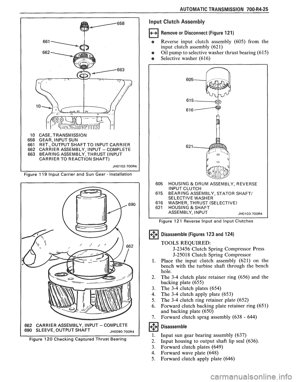
10 CASE, TRANSMISSION
658 GEAR, INPUT SUN 661 RET., OUTPUT SHAFT TO INPUT CARRIER 662 CARRIER ASSEMBLY, INPUT -COMPLETE 663 BEARING ASSEMBLY, THRUST (INPUT
CARRIER TO REACTION SHAFT)
JH0102-700R4
Figure 1 19 lnput Carrier and Sun Gear - Installation
662 CARRIER ASSEMBLY, INPUT -COMPLETE 690 SLEEVE, OUTPUT SHAFT JHOO~O-700~4
Figure 120 Checking Captured Thrust Bearing
lnput Clutch Assembly
Remove or Disconnect (Figure 121)
e Reverse input clutch assembly (605) from the
input clutch assembly (62 1)
e Oil pump to selective washer thrust bearing (61 5)
e Selective washer (616)
605 HOUSING & DRUM ASSEMBLY, REVERSE
INPUT CLUTCH
615 BEARING ASSEMBLY, STATOR SHAFT1 SELECTIVE WASHER
616 WASHER, THRUST (SELECTIVE) 621 HOUSING & SHAFT
ASSEMBLY, INPUT
~~0103-700134
Figure 12 1 Reverse lnput and lnput Clutches
+'+ Disassemble (Figures 123 and 124) (I]
TOOLS REQUIRED:
J-23456 Clutch Spring Compressor Press
J-25018 Clutch Spring Compressor
1. Place the input clutch assembly (621) on the
bench with the turbine shaft through the bench
hole.
2. The 3-4 clutch plate retainer ring (656) and the
backing plate (655)
3. The
3-4 clutch plates (654)
4. The 3-4 clutch apply plate (653)
5. The 3-4 clutch ring retainer plate (652)
6. Forward
clutch backing plate retainer ring (65
1)
and backing plate (650)
7. Forward clutch sprag assembly (638 - 644)
Disassem bie
1. Input sun gear bearing assembly (637)
2. Input
housing to output shaft lip seal (636).
3. Forward clutch plates (649)
4. Forward wave plate (648)
5. Forward clutch apply plate (646)
Page 1092 of 1825
AUTQMATIC TRANSMISSION 700-R4-41
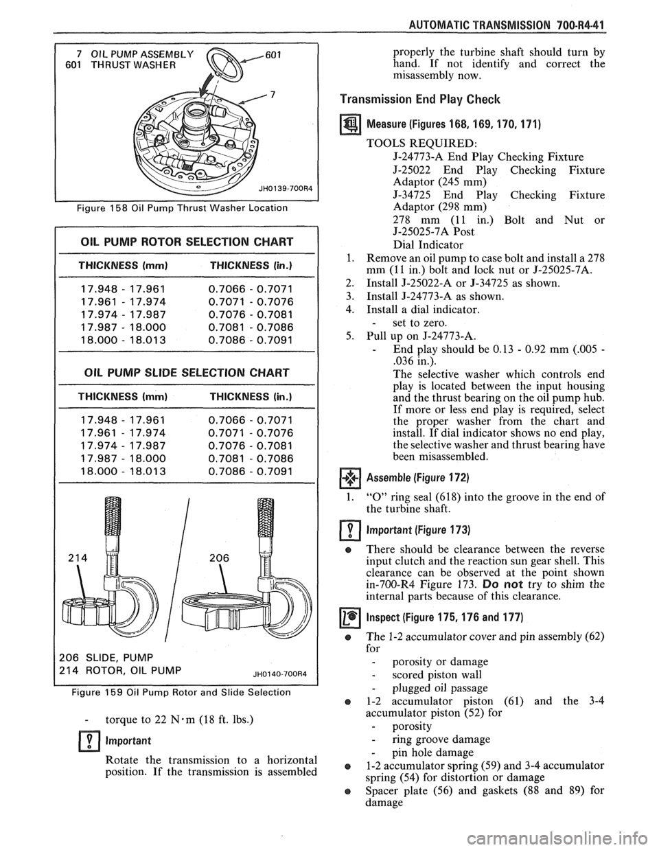
Figure 158 Oil Pump Thrust Washer Location
I OIL PUMP ROTOR SELECTION CHART I
I THICKNESS (mml THICKNESS (in.)
17.948 - 17.961
0.7066 - 0.7071
17.961
- 17.974 0.7071 - 0.7076
17.974
- 17.987 0.7076 - 0.7081
17.987
- 18.000 0.7081 - 0.7086
18.000
- 18.01 3 0.7086 - 0.7091
OIL PUMP SLlDE SELECTION CHART
THICKNESS (mm) THICKNESS (in.)
206 SLIDE, PUMP
214 ROTOR OIL PUMP
Figure 159 Oil Pump Rotor and Slide Selection
- torque to 22 N-m (18 ft. lbs.)
lmportant
Rotate the transmission to a horizontal
position. If the transmission is assembled properly
the turbine shaft should turn by
hand. If not identify and correct the
misassembly now.
Transmission End Play Checlc
a Measure (Figures 168, 169, 170. 171)
TOOLS REQUIRED:
5-24773-A End Play Checking Fixture
J-25022 End Play Checking Fixture
Adaptor (245 mm)
5-34725 End Play Checking Fixture
Adaptor (298 mm)
278 mm (11 in.) Bolt and Nut or
J-25025-7A
Post
Dial Indicator
1. Remove an oil pump to case bolt and install a 278
mm (11 in.) bolt and
lock nut or J-25025-7A.
2. Install 5-25022-A or
5-34725 as shown.
3. Install
J-24773-A as shown.
4. Install a dial indicator.
- set to zero.
5. Pull up on J-24773-A.
- End play should be 0.13 - 0.92 mm (.005 -
,036 in.).
The selective washer which controls end
play is located between the input housing
and the thrust bearing on the oil pump hub.
If more or less end play is required, select
the proper washer from the chart and
install. If dial indicator shows no end play,
the selective washer and thrust bearing have
been misassembled.
Assemble (Figure 172)
1. "0" ring seal (618) into the groove in the end of
the turbine shaft.
lmportant (Figure 173)
e There should be clearance between the reverse
input clutch and the reaction sun gear shell. This
clearance can be observed at the point shown
in-700-R4 Figure 173.
Do not try to shim the
internal parts because of this clearance.
Inspect (Figure 175,176 and 177) -
e The 1-2 accumulator cover and pin assembly (62)
for
- porosity or damage
- scored piston wall
- plugged oil passage
e 1-2 accumulator piston (61) and the 3-4
accumulator piston (52) for
- porosity
- ring groove damage
- pin hole damage
e 1-2 accumulator spring (59) and 3-4 accumulator
spring (54) for distortion or damage
e Spacer plate (56) and gaskets (88 and 89) for
damage
Page 1108 of 1825
AUTOMATIC TRANSMISSION 700-R4-57
If:
e
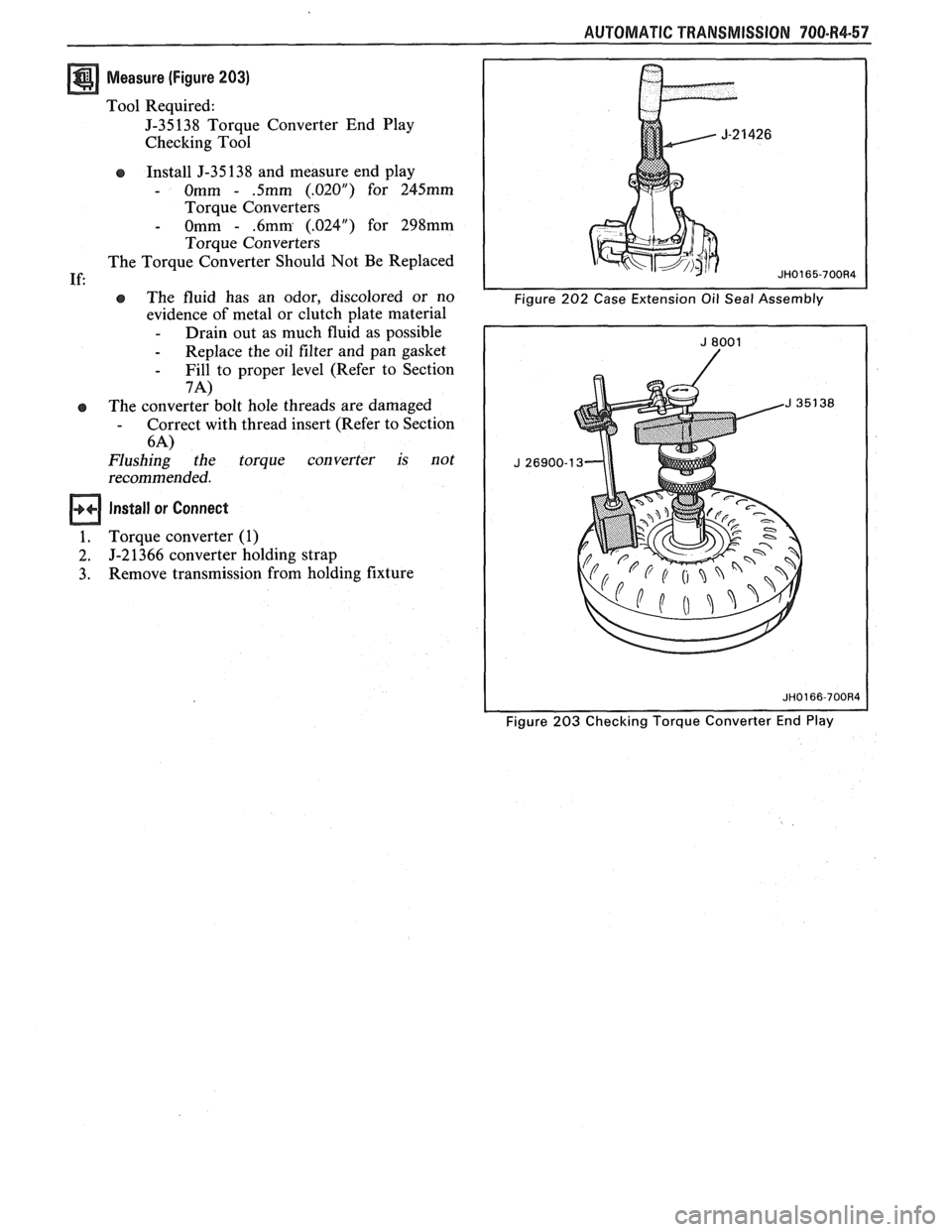
Measure (Figure 203)
Tool Required:
J-35138 Torque Converter End Play
Checking Tool
Install J-35 138 and measure end play
- Omm - .5mm (.02OU) for 245mm
Torque Converters
- Omm - .6mm (.024") for 298mm
Torque Converters
The Torque Converter Should Not Be Replaced
e The fluid has an odor, discolored or no
evidence of metal or clutch plate material
- Drain out as much fluid as possible
- Replace the oil filter and pan gasket
- Fill to proper level (Refer to Section
7A)
The converter bolt hole threads are damaged - Correct with thread insert (Refer to Section
6-4)
Flushing the torque converter is not
recommended.
Install or Connect
Torque converter (1)
J-2 1366 converter holding strap
Remove transmission from holding fixture
Figure 203 Checking Torque Converter End Play
Page 1115 of 1825
780-R4-64 AUTOMATIC TRANSMISSION
-
Universal Remover Dial Indicator Set
I - -
1 Pump Oil Seal Installer I Piston Compressor 1 Bushing Remover I
Clutch Spring Compressor Clutch Spring
Compressor
J-25022
End Play Checking Fixture Adaptor Bushing
Remover
Figure
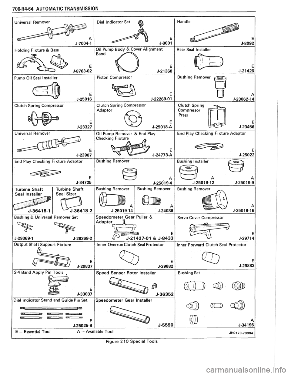
2 10 Special Tools
Page 1126 of 1825
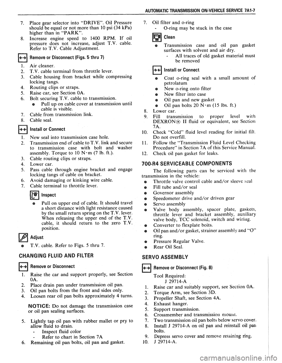
AUTOMATIC TRANSMISSION ON-VEHICLE SERVICE 7A1-7
7. Place
gear selector into "DRIVE". Oil Pressure
should be equal or not more than 10 psi
(34 kPa)
higher than in "PARK".
8. Increase engine speed to 1400 RPM. If oil
pressure does not increase, adjust
T.V. cable.
Refer to T.V. Cable Adjustment.
Remove or Disconnect (Figs. 5 thru 7)
1. Air cleaner.
2. T.V. cable terminal from throttle lever.
3. Cable housing from bracket while compressing
locking tangs.
4. Routing clips or straps.
5. Raise
car, see Section OA.
6. Bolt securing T.V. cable to transmission.
o Pull up on cable cover at transmission until
cable is visible.
7. Cable from transmission link.
8. Cable seal.
Install or Connect
1. New seal into transmission case hole.
2. Transmission end of cable to T.V. link and secure
to transmission case with bolt and washer
assembly. Torque to 10
Nam (7 Ib. ft.).
3. Cable routing clips or straps.
4. Lower car.
5. Pass cable through engine bracket and engage
locking tangs of cable on bracket.
6. Avoid damaging or kinking wire cable.
7. Cable terminal to throttle lever.
Inspect
o Pull on upper end of cable. It should travel
a short distance with light resistance caused
by the small return spring on the
T.V. lever.
When releasing the upper end of the T.V.
cable, it should return to the zero T.V.
position.
Adjust
o T.V. cable. Refer to Figs. 5 thru 7.
CHANGING FLUID AND FILTER
Remove or Disconnect
1. Raise the car and support properly, see Section
OA.
2. Place drain pan under transmission oil pan.
3. Oil pan bolts from the front and sides only.
4. Loosen rear oil pan bolts approximately 4 turns.
NOTICE: Do not damage the transmission case
or oil pan sealing surfaces.
5. Lightly tap oil pan with rubber mallet or pry to
allow fluid to drain.
- Inspect fluid color
- Refer to chart in Section 7A
6. Remaining oil pan bolts, oil pan and gasket. 7. Oil filter
and o-ring
- O-ring may be stuck in the case
e Transmission case and oil pan gasket
surfaces with solvent and air dry.
- All traces of old gasket material must
be removed
Install or Connect
o Coat o-ring seal with a small amount of
petrolatum
o New o-ring onto filter
e New filter into case
a Oil pan and new gasket
e Oil pan bolts 20 N.m (15 lbs. ft.)
8. Lower car.
9. Fill transmission to proper level with
DEXRONO I1 fluid or equivalent, see Section
7A.
10. Check "Cold"
fluid level reading for initial till.
Do not overfill.
11. Follow
the "Transmission Fluid Level Checking
Procedure" in Section 7A of this Service Manual.
12. Check
oil pan gasket for leaks.
700-R4 SERVICEABLE COMPONENTS
The following parts can be serviced with the
transmission in the vehicle:
o Throttle valve control cable and/or sleeve heal
Fill tube and/or seal
o Governor assembly
a Speedometer drive and/or driven gear
e Servo assembly
a Valve body assembly, spacer plate, gaskets,
throttle lever and bracket assembly, auxiliary
valve body, TCC solenoid, switch and
wir-iug.
a Converter to flexplate bolts.
a Oil pan and/or gasket, strainer assembly and "0"
ring.
e Pressure Regular Valve.
o Rear Oil Seal.
SERVO ASSEMBLY
Remove or Disconnect (Fig. 8)
Tool Required:
J 29714-A
1. Raise car and suitably support, see Section OA.
2. Torque Arm,
see Section
3D.
3. Propeller Shaft, see Section 4A.
4. Exhaust hanger.
5. Support transmission.
6. Crossmember and transmission moulll.
7. Two
transmission oil pan bolts below servo cover.
8. Install J 29714-A on oil pan and reinstall oil pan
bolts.
9. Depress servo cover
and remove retaining ring.
10. J 29714-A.
Page 1163 of 1825
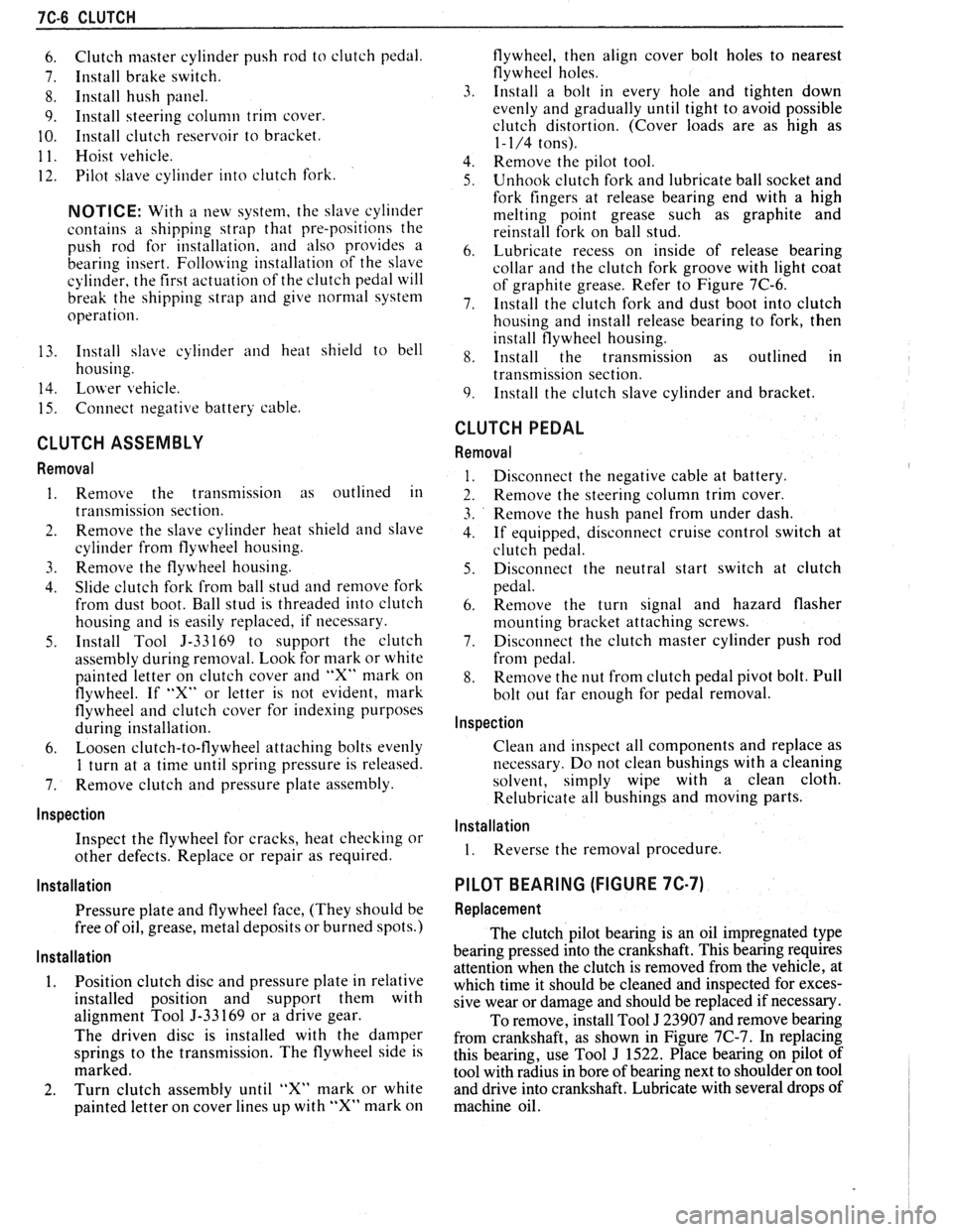
7C-6 CLUTCH
6. Clutch master cylinder push rod to clutch pedal.
7. Install brake switch.
8. Install hush panel.
9. Install steering column trim cover.
10. Install clutch reservoir to bracket.
1 1. Hoist vehicle.
12. Pilot slave cylinder into clutch fork.
NOTICE: With a new system, the slave cylinder
contains a shipping strap that pre-positions the
push rod for installation, and also provides a
bearing insert.
Follojving installation of the slave
cylinder, the first actuation of the clutch pedal will
break the shipping strap and give
normal system
operation.
13. Install slave cylinder and heat shield to bell
housing.
14.
Lojver vehicle.
15. Connect negative battery cable.
CLUTCH ASSEMBLY
Removal
1. Remove the transmission as outlined in
transmission section.
2. Remove the slave cylinder heat shield and slave
cylinder
from flywheel housing.
3. Reniove the flywheel housing.
4. Slide clutch fork from ball stud and remove fork
from dust boot. Ball stud is threaded into clutch
housing and is easily replaced, if necessary.
5. Install Tool 5-33169 to support the clutch
assen~bly during removal. Look for mark or white
painted letter on clutch cover and
"X" mark on
flywheel. If
"Xu or letter is not evident, mark
flywheel and clutch cover for indexing purposes
during installation.
6. Loosen clutch-to-flywheel attaching bolts evenly
1 turn at a time until spring pressure is released.
7. Remove clutch and pressure plate assembly.
lnspection
Inspect the flywheel for cracks, heat checking or
other defects. Replace or repair as required.
Installation
Pressure plate and flywheel face, (They should be
free of oil, grease, metal deposits or burned spots.)
Installation
1. Position clutch disc and pressure plate in relative
installed position and support them with
alignment Tool J-33169 or a drive gear.
The driven disc is installed with the damper
springs to the transmission. The flywheel side is
marked.
2. Turn clutch assembly until "X" mark or white
painted letter on cover lines up with
"X" mark on flywheel,
then align cover bolt holes to nearest
flywheel holes.
3. Install a bolt in every hole and tighten down
evenly and gradually until tight to avoid possible
clutch distortion. (Cover loads are as high as
1- 1/4 tons).
4. Remove the pilot tool.
5. Unhook clutch fork and lubricate ball socket and
fork fingers at release bearing end with a high
melting point grease such as graphite and
reinstall fork on ball stud.
6. Lubricate recess on inside of release bearing
collar and the clutch fork groove with light coat
of graphite grease. Refer to Figure 7C-6.
7. Install the clutch fork and dust boot into clutch
housing and install release bearing to fork, then
install flywheel housing.
8. Install the transmission as outlined in
transmission section.
9. Install the clutch slave cylinder and bracket.
CLUTCH PEDAL
Removal
Disconnect the negative cable at battery.
Remove the steering column trim cover.
Remove the hush panel from under dash.
If equipped, disconnect cruise control switch at
clutch pedal.
Disconnect the neutral start switch at clutch
pedal.
Renlove the turn signal and hazard flasher
mounting bracket attaching screws.
Disconnect the clutch master cylinder push rod
from pedal.
Remove the nut from clutch pedal pivot bolt. Pull
bolt out far enough for pedal removal.
Inspection
Clean and inspect all components and replace as
necessary. Do not clean bushings with a cleaning
solvent, simply wipe with a clean cloth.
Relubricate all bushings and moving parts.
Installation
1. Reverse the removal procedure.
PILOT BEARING (FIGURE 7C-7)
Replacement
The clutch pilot bearing is an oil impregnated type
bearing pressed into the crankshaft. This bearing requires
attention when the clutch is removed from the vehicle, at
which time it should be cleaned and inspected for exces-
sive wear or damage and should be replaced if necessary.
To remove, install Tool
J 23907 and remove bearing
from crankshaft, as shown in Figure
7C-7. In replacing
this bearing, use Tool
J 1522. Place bearing on pilot of
tool with radius in bore of bearing next to shoulder on tool
and drive into crankshaft. Lubricate with several drops of
machine oil.
Page 1812 of 1825
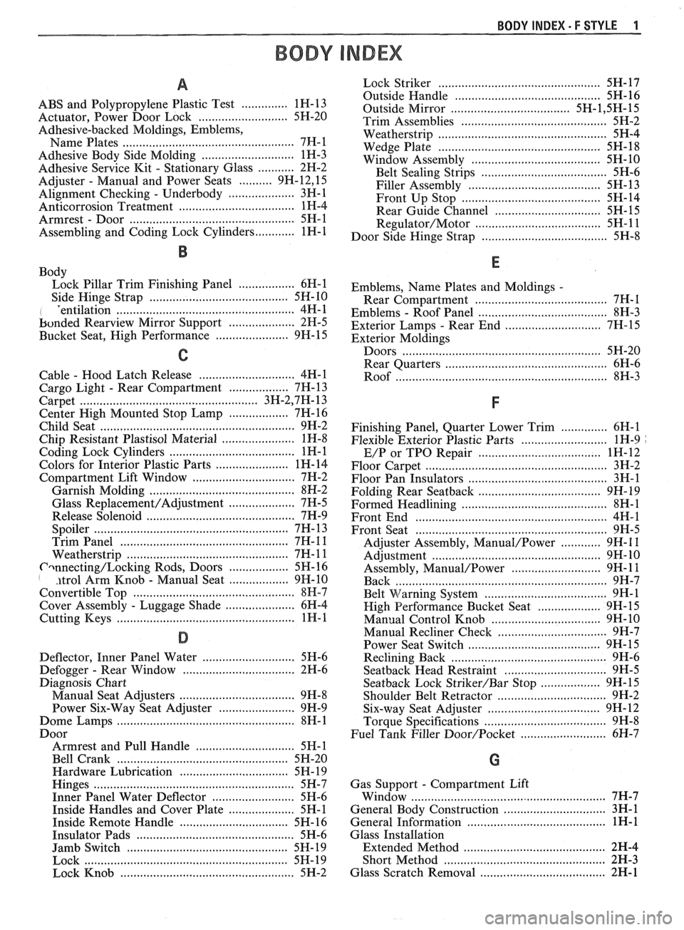
BODY INDEX . F STYLE 1
BODY INDEX
a
ABS and Polypropylene Plastic Test .............. 1 H- 13
Actuator. Power Door Lock
.......................... 5H-20
Adhesive-backed Moldings. Emblems. Name Plates
.................................................... 7FI-1
Adhesive Body Side Molding ............................ 1H-3
Adhesive Service
Kit . Stationary Glass ........... 2H-2
Adjuster
. Manual and Power Seats .......... 9H.12. 15
Alignment Checking
. Underbody .................... 3H-1
Anticorrosion Treatment
................................... 1H-4
Armrest
. Door ................................................. 5H-1
Assembling and Coding
Lock Cylinders ............ 1H-1
B
Body
Lock Pillar Trim Finishing Panel
................. 6H-1
Side Hinge Strap
......................................... 5H-10
I 'entilation ................................... .... ............... 4H-1
bonded
Rearview Mirror Support .................... 2H-5
Bucket Seat. High Performance
...................... 9H- 15
C
............................. Cable . Hood Latch Release 4H-1
Cargo Light
. Rear Compartment .................. 7H- 13
..................................................... Carpet 3H.2,7 H. 13
Center High Mounted Stop Lamp
.................. 7H-16
Child Seat
........................................................... 9H-2
Chip Resistant Plastisol Material
...................... 1H-8
...................................... Coding Lock Cylinders 1
H- 1
Colors for Interior Plastic Parts ...................... 1H-14
............................. Compartment Lift Window 7H-2
Garnish Molding
........................................ 8H-2
Glass
Replacement/Adjustment .................... 7H-5
Release Solenoid
.......................................... 7H-9
.......................................................... Spoiler 7H- 13
.................................................. Trim Panel 7H- 1 1
................................................ Weatherstrip 7H- 1 1
Cwnecting/Locking Rods, Doors .................. 5H- 16 I . itrol Arm Knob . Manual Seat .................. 9H-10
Convertible Top
................................................ 8H-7
Cover Assembly
. Luggage Shade ..................... 6H-4
................................................... Cutting Keys 1H- 1
D
............................ Deflector. Inner Panel Water 5H-6
Defogger
. Rear Window .................................. 2H-6
Diagnosis Chart
................................... Manual Seat Adjusters 9H-8
Power Six-Way Seat Adjuster
....................... 9H-9
Dome Lamps
...................................................... 8H-1
Boor Armrest and Pull Handle
.............................. 5H-1
Bell Crank
.................................................... 5H-20
Hardware Lubrication
................................. 5H- 19
Hinges
............................................................. 5H-7
Inner Panel Water Deflector
......................... 5H-6
Inside Handles and Cover Plate
.................... 5H-1
Inside Remote Handle
................................. 5H-16
Insulator Pads
............................................. 5H-6
Jamb Switch
................................................. 5H-19
Lock
.............................................................. 5H- 19
Lock Knob
..................................................... 5H-2
................................................. Lock Striker 5H- 17
............................................ Outside Handle 5H- 16
Outside Mirror
................................... 5H- 1.5 H. 15
Trim Assemblies
............................................ 5H-2
................................................... Weatherstrip 5H-4
................................................. Wedge Plate 5H-18
....................................... Window Assembly 5H- 10
...................................... Belt Sealing Strips 5H-6
........................................ Filler Assembly 5H- 13
.......................................... Front Up Stop 5H-14
................................ Rear Guide Channel 5H- 15
Regulator/Motor .................................... 5H-11
...................................... Door Side Hinge Strap 5H-8
Emblems.
Name Plates and Moldings .
Rear Compartment ........................................ 7H-I
. ....................................... Emblems Roof Panel 8H-3
. ............................. Exterior Lamps Rear End 7H-15
Exterior Moldings
Doors
............................................................ 5H-20
............................................... Rear Quarters 6H-6
.............................................................. Roof 8W-3
Finishing Panel. Quarter Lower Trim .............. 6H-1
Flexible Exterior Plastic Parts
.......................... 1H-9 .
.................................. E/P or TPO Repair 1H-12
Floor Carpet
................................................... 3H-2
Floor Pan Insulators
............................ .. ........ 3H-1
Folding Rear
Seatback ........................ ... ...... 9H- 19
Formed Headlining
.......................................... 8H-1
........................................................ Front End 4H-1
.......................................................... Front Seat 9H-5
............ Adjuster Assembly. Manual/Power 9H- 1 1
................................................... Adjustment 9H- 10
........................... Assembly. Manual/Power 9H- 1 1
................................................................ Back 9H-7
. ................................ Belt Warning System .... 9H-1
................... High Performance Bucket Seat 9H-
15
............................... Manual Control Knob 9H- 10
................................. Manual Recliner Check 9H-7
........................................ Power Seat Switch 9H- 15
............................................. Reclining Back 9H-6
............................... Seatback Head Restraint 9H-5
.................. Seatback Lock Striker/Bar Stop 9H-15
................................. Shoulder Belt Retractor 9H-2
................................. Six-way Seat Adjuster 9H-12
................................... Torque Specifications 9H-8
Fuel Tank Filler
Door/Pocket ........................ 6H-7
Gas Support
. Compartment Lift
........................................................... Window 7H-7
............................... General Body Construction 3H-1
.......................................... General Information 1H-1
Glass Installation
........................................... Extended Method 2H-4
................................................. Short Method 2H-3
...................................... Glass Scratch Removal 2H- 1