battery PONTIAC FIERO 1988 Service Repair Manual
[x] Cancel search | Manufacturer: PONTIAC, Model Year: 1988, Model line: FIERO, Model: PONTIAC FIERO 1988Pages: 1825, PDF Size: 99.44 MB
Page 2 of 1825
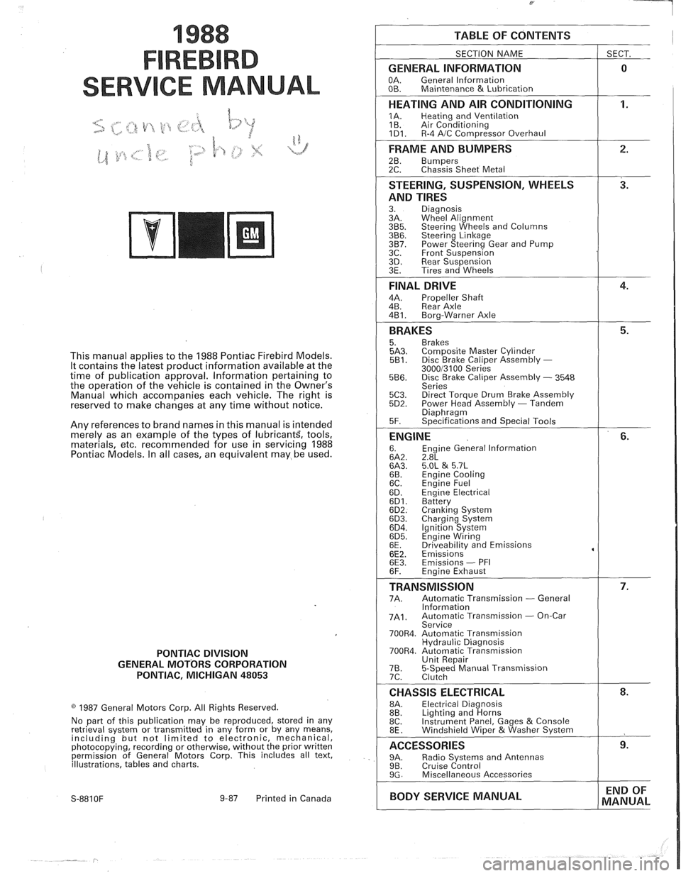
1988
SER
This manual applies to the 1988 Pontiac Firebird Models.
It contains the latest product information available at the
time of publication approval. lnformation pertaining to
the operation of the vehicle is contained in the Owner's
Manual which accompanies each vehicle. The right is
reserved to make changes at any time without notice.
Any references to brand names in this manual is intended
merely as an example of the types of
lubricant% tools,
materials, etc, recommended for use in servicing 1988
Pontiac Models. In all cases, an equivalent may be used.
PONTIAC DIVISION
GENERAL
MOTORS CORPORATION
PONTIAC, MICHIGAN 48053
1987 General Motors Corp. All Rights Reserved.
No part of this publication may be reproduced, stored in any
retrieval system or transmitted in any form or by any means,
including but not limited to electronic, mechanical,
photocopying, recording or otherwise, without the prior written
permission of General Motors Corp. This includes all text,
illustrations, tables and charts.
S-881 OF 9-87 Printed in Canada
TABLE OF CONTENTS
SECTION NAME
GENERAL INFORMATION
OA. General lnformation
OB. Maintenance & Lubrication
1 SECT.
HEATING AND AIR CONDITIONING
1A. Heating and Ventilation
1 B. Air Conditioning
1D1. R-4 AIC Com~ressor Overhaul
FRAME AND BUMPERS
2B. Bumpers 2C. Chassis Sheet Metal
STEERING, SUSPENSION, WHEELS
AND TIRES
3. Diagnosis
3A. Wheel Alignment
3B5. Steering Wheels and Columns 3B6. Steering Linkage 3B7. Power Steering Gear and Pump
3C. Front Suspension
3D. Rear Suspension
3E. Tires and Wheels
FINAL DRIVE
4A. Propeller Shaft
4B. Rear Axle
4B1. Bora-Warner Axle
BRAKES 5. Brakes 5A3. Comoosite Master Cvlinder 5B1. Disc r rake Caliper ~ssembly - 300013100 Series 5B6. Disc Brake Caliper Assembly - 3548
Series
5C3. Direct Torque Drum Brake Assembly 5D2. Power Head Assembly - Tandem Diaohraam 5F. ~~ecifications and Special Tools
ENGINE 6. Engine General lnformation 6A2. 2.8L 6A3. 5.OL & 5.7L 6B. Engine Cooling
6C. En~ine Fuel
6D. ~ngine Electrical 6D1. Battery 6D2. Cranking System 6D3. Charging System 6D4. Ignition System 6D5. Engine Wiring
6E. Driveabilitv and Emissions
6E2. ~missions' 6E3. Emissions - PFI
6F. Engine Exhaust
TRANSMISSION 7A. Automatic Transmission - General
lnformation
7A1. Automatic Transmission - On-Car
Service
700R4. Automatic Transmission Hydraulic Diagnosis
700R4. Automatic Transmission Unit Repair
76. 5-Speed Manual Transmission
7C. Clutch
CHASSIS ELECTRICAL 8A. Electrical Diagnosis
8B. Lighting and Horns
8C. Instrument
Panel, Gages
& Console
8E. Windshield Wiper &Washer System
ACCESSORIES 9A. Radio Systems and Antennas 9B. Cruise Control 9G. Miscellaneous Accessories
I BODY SERVICE MANUAL END
OF
MANUAL
Page 36 of 1825
HEATING AND VENTILATION 1.4-1 3
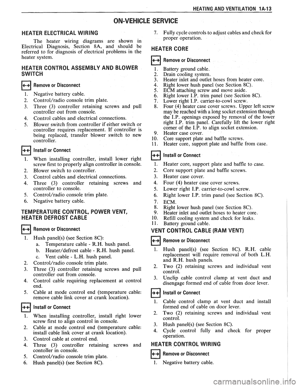
ON-VEHICLE SERVICE
HEATER ELECTRICAL WIRING
The heater wiring diagrams are shown in
Electrical Diagnosis, Section
8A, and should be
referred to for diagnosis of electrical problems in the
heater system.
HEATER CONTROL ASSEMBLY AND BLOWER
SWITCH
Remove or Disconnect
1. Negative battery cable.
2.
Control/radio console trim plate.
3. Three
(3) controller retaining screws and pull
controller out from console.
4. Control cables and electrical connections.
5. Blower switch from controller if either switch or
controller requires replacement. If controller is
being replaced, transfer blower switch to new
controller.
Install or Connect
1. When installing controller, install lower right
screw first to properly align controller in console.
2. Blower switch to controller.
3. Control cables and electrical connections.
4. Three (3) controller retaining screws and
controller to console.
5. Control/radio console trim plate.
6. Negative battery cable.
TEMPERATURE CONTROL, POWER VENT,
HEATER DEFROST CABLE
Remove or Disconnect
1. Hush panel(s) (see Section 8C):
a. Temperature
cable - R.H. hush panel.
b.
Heateddefrost cable - R.H. hush panel.
c. Vent
cable
- L.H. hush panel.
2.
Control/radio console trim plate.
3. Three (3) controller retaining screws and pull
controller out from console.
4. Control cable requiring replacement at control
end.
5. Cable at mode control end (temperature cable:
remove cable link cover at crank location).
Install or Connect
1. When installing controller, install right lower
screw first to align control in console.
2. Cable
at mode control end (temperature cable:
install cable link cover at crank location).
3. Control cable at control end.
4. Three (3) controller retaining screws and
contoller in console.
5. Control/radio console trim plate.
6. Hush panel(s) (see Section 8C).
7. Fully cycle controls to adjust cables and check for
proper operation.
HEATER CORE
Remove or Disconnect
Battery ground cable.
Drain cooling system.
Heater inlet and outlet hoses from heater core.
Right lower hush panel (see Section
8C).
ECM attaching screw and move aside.
Right lower I.P. trim panel (see Section
8C).
Lower right I.P. carrier-to-cowl screw.
Four (4) heater case cover screws. Upper left screw
may be reached with a long socket extension through
the I.P. openings exposed by removal of the lower
right I.P. trim panel. Carefully lift the lower right
corner of the I.P. to align socket extension.
Heater case cover.
Core support plate and baffle screws.
Heater core, support plate and baffle from case.
Install or Connect
1. Heater core, support plate and baffle to case.
2. Core support
plate and baffle screws.
3. Heater case cover.
4. Four (4) heater case cover screws.
5. Lower right I.P. carrier-to-cowl screw.
6. Right lower I.P. trim panel (see Section 8C).
7. ECM.
8. Right lower hush panel (see Section
8C).
9. Heater inlet and outlet hoses to heater core.
10. Refill cooling system and check for leaks.
11. Battery ground cable.
VENT CONTROL CABLE (RAM VENT)
Remove or Disconnect 1
1. Hush panel(s) (see Section 8C). R.H. cable
replacement will require removal of both L.H.
and R.H. hush panels.
2. Two
(2) retaining screws and individual vent
control.
3. Unclip
cable control clamp at vent duct and
disengage formed end of cable from door lever.
1 Install or Connect
1. Cable control clamp at vent duct and install
formed end of cable on door lever.
2, Two (2) retaining screws and individual vent
control.
3. Hush
panel@) (see Section 8C).
4. Cycle
control fully and check for proper
operation.
HEATER CONTROL WIRING I
Remove or Disconnect
1. Negative battery cable.
Page 37 of 1825
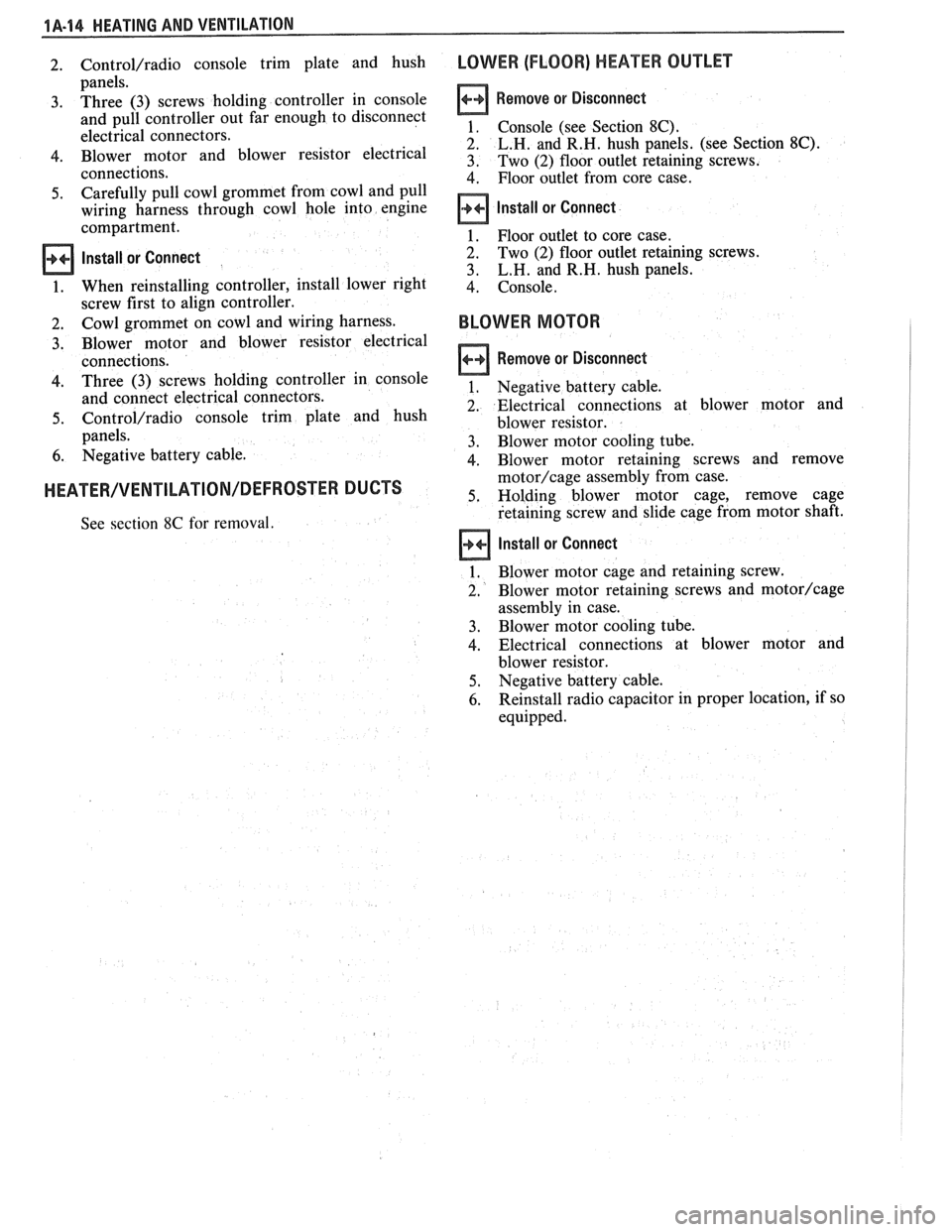
1A-14 HEATING AND VENTILATION
2. Control/radio console trim plate and hush
panels.
3. Three (3) screws holding controller in console
and pull controller out far enough to disconnect
electrical connectors.
4. Blower motor and blower resistor electrical
connections.
5. Carefully pull cowl grommet from cowl and pull
wiring harness through cowl hole into engine
compartment.
Install or Connect
1. When reinstalling controller, install lower right
screw first to align controller.
2. Cowl grommet on cowl and wiring harness.
3. Blower motor and blower resistor electrical
connections.
4. Three (3) screws holding controller in console
and connect electrical connectors.
5. Control/radio console trim plate and hush
panels.
6. Negative battery cable.
HEATER/VENTILATION/DEFROSTER DUCTS
See section 8C for removal.
LOWER (FLOOR) HEATER OUTLET
Remove or Disconnect
1. Console (see Section 8C).
2. L.H. and R.H. hush panels. (see Section 8C).
3. Two (2) floor outlet retaining screws.
4. Floor outlet from core case.
Install or Connect
1. Floor outlet to core case.
2. Two (2) floor outlet retaining screws.
3. L.H. and R.H. hush panels.
4. Console.
BLOWER MOTOR
Remove or Disconnect
1. Negative battery cable.
2. Electrical connections at blower motor and
blower resistor.
3. Blower motor cooling tube.
4. Blower motor retaining screws and remove
motor/cage assembly from case.
5. Holding blower motor cage, remove cage
retaining screw and slide cage from motor shaft.
Install or Connect
1. Blower motor cage and retaining screw.
2. Blower
motor retaining screws and
motor/cage
assembly in case.
3. Blower motor cooling tube.
4. Electrical connections at blower motor and
blower resistor.
5. Negative battery cable.
6. Reinstall radio capacitor in proper location, if so
equipped.
Page 55 of 1825
18-12 AIR CONDITIONING
ELEGTRICAWACUUM SYSTEM
DIAGNOSIS
When diagnosing problems in the electrical sys-
tems of the air conditioning system, consult section
8A.
LEAK TESTING THE REFRIGERANT
SYSTEM
Whenever a refrigerant leak is suspected in the
system or a service operation performed which results
in disturbing lines or connections, it is advisable to
test for leaks.
Liquid Leak Detectors
There are a number of locations (fittings,
valves, etc.) on the air conditioning system where a
liquid leak detector solution may be used to pinpoint
refrigerant leaks.
By applying test solution to the area in question
with the swab that is attached to the bottle cap, bub-
bles will form within seconds if there is a leak.
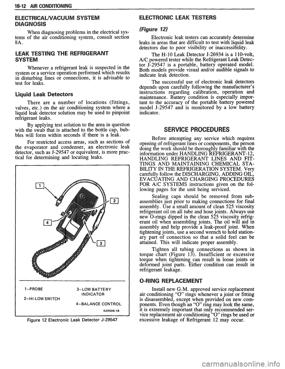
For restricted access areas, such as sections of
the evaporator and condenser, an electronic leak
detector, such as
5-29547 or equivalent, is more prac-
tical for determining and locating leaks.
3-LOW BATTERY
INDICATOR
2-HI-LOW SWITCH
4-BALANCE CONTROL
Figure 12 Electronic Leak Detector J-29547
ELECTRONIC LEAK TESTERS
(Figure 12)
Electronic leak testers can accurately determine
leaks in areas that are difficult to test with liquid leak
detectors due to poor visibility or inaccessibility.
The H-10 Leak Detector 5-26934 is a 110-volt,
A/C powered tester while the Refrigerant Leak Detec-
tor J-29547 is a portable, battery operated model.
Both models provide visual
and/or audible signals to
indicate leak detection.
The successful use of electronic leak detectors
depends upon carefully following the manufacturer's
instructions regarding calibration, operation and
maintenance. Battery condition is especially impor-
tant to the accuracy of the portable battery powered
model
5-29547 and is monitored by a low battery
indicator.
SERVICE PROCEDURES
Before attempting any service which requires
opening of refrigerant lines or components, the person
doing the work should be thoroughly familiar with the
information under HANDLING REFRIGERANT- 12,
HANDLING REFRIGERANT LINES AND FIT-
TINGS AND MAINTAINING CHEMICAL STA-
BILITY IN THE REFRIGERATION SYSTEM. Very
carefully follow the DISCHARGING, ADDING OIL,
EVACUATING AND CHARGING PROCEDURES
FOR
A/C SYSTEMS instructions given on the fol-
lowing pages for the unit being serviced.
Sealing caps should be removed from sub-
assemblies just prior to making connections for final
assembly. Use a small amount of clean 525 viscosity
refrigerant oil on all tube and hose joints. Always use
new O-rings dipped in the clean 525 viscosity refrig-
erant oil when assembling joints. The oil will aid in
assembly and help provide a leak-proof joint. When
tightening joints, use a second wrench to hold station-
ary part of connection so that
a solid feel can be
attained. This will indicate proper assembly.
Tighten all tubing connections as shown in
torque chart (Figure
13). Insufficient or excessive
torque when tightening can result in loose joints or
deformed joint parts. Either condition can result in
refrigerant leakage.
O-RING REPWCEMENT
Install new G. M. approved service replacement
air conditioning
"0" rings whenever a joint or fitting
is disassembled, except when provided on new com-
ponents. Even though an
"0" ring may look the same,
it is extremely important that only recommended ser-
vice replacement air conditioning
"0" rings be used or
excessive leakage of Refrigerant 12 may occur.
Page 63 of 1825
18-28 AIR CONDITIONING
DO NOT REPLACE the accumulator assembly
when:
1. Merely a dent is found in the outer shell of the
accumulator.
2. A
vehicle is involved in a collision and no phys-
ical perforation to the accumulator is found.
OM-VEHICLE SERVICE
R-"1 CHARGING CAPACITIES
The 420ml (14 fl. oz.) disposable can of R-12
refrigerant is equivalent to .399 kg (. 88 lb.).
BLOWER MOTOR
a Remove or Disconnect
1. Disconnect negative battery cable.
2. Remove motor cooling tube.
3. Disconnect electrical connections.
4. Remove blower motor attaching screws, remove
motor and case assembly.
5. Loosen retaining nut and remove blower cage
from motor shaft.
6. Inspect blower cage for broken vanes, etc.
Replace if necessary.
Install or Connect
1. Reverse removal procedure to reinstall. Replace
seals or sealant as required.
HI-BLOWER RELAY
Relay is a plug-in type with connector mounted
on top of the evaporator case.
BLOWER RESISTOR
Remove or Disconnect
1. Disconnect negative battery cable.
2. Disconnect electrical connections.
3. Remove two (2) screws, remove resistor.
Install or Connect
1. Reverse removal procedure to reinstall.
CONTROLLER, BLOWER SWITCH OR
WCUUM VALVE
Remove or Disconnect
1. Disconnect negative battery cable.
2. Remove NC control-radio console trim plate.
3. Remove three (3) NC control retaining screws.
4. Pull A/C control out and disconnect electrical
and vacuum connections and remove tempera-
ture cable.
5. Remove A/C control and replace vacuum valve
or blower switch as required.
Install or Connect
1. Reverse removal procedure to reinstall. Install
lower right screw in controller first to align con-
troller in console.
TEMPERATURE CONTROL CABLE,
VACUUM HARNESS
Remove or Disconnect
1. Remove the following hush panel(s):
a. Vacuum Harness - R.H. and L.H. hush
panel.
b. Temperature Cable
- R.H. hush panels.
Remove
controller/radio console trim plate.
Remove three (3) controller screws and pull
controller partially out of console.
Disconnect controller
end(s) of temperature
cable
andlor vacuum harness.
Disconnect component
end(s) of temperature
cable
andlor vacuum harness.
Install or Conned
1. Reverse removal procedure to reinstall. When
installing controller, install lower right screw
first to align controller location. Replace any
retaining straps, etc. removed.
2. Perform functional check of controller.
CONTROL WlRlNG HARNESS
a Remove or Disconnect
1. Disconnect negative battery cable.
2. Remove
control/radio console trim plate and
hush panels (see Section
8C).
3. Remove three (3) screws holding control in con-
sole and pull control out far enough to discon-
nect electrical and vacuum connector. Remove
controller.
4. Remove instrument panel carrier (see Section
8C).
5. Remove heater case covers (core and mode door
sides).
6. Remove two (2) interior screws and one (1)
exterior nut holding case to cowl. Pull left side
of case back to gain access to harness at cowl.
Case will still be retained by one (I) screw
behind the evaporator core
- do not attempt
complete removal of case. -
7. Loosen cowl grommet and disconnect purple
vacuum line.
Page 64 of 1825
AIR CONDITIONING 18-21
8. Disconnect blower motor
and blower resistor
electrical connection.
9. Remove hi-blower relay connector from evapo-
rator case.
10. Carefully pull
cowl grommet from cowl and pull
wiring
hmess into engine compartment.
Install or Connect
1. Reverse removal procedure to
reinstall. When
reinstalling controller, install lower right screw
first to align controller.
ACNENTILATIONIDEFROSVER DUCTS
See section 8C for removal.
HEATER CORE
Remove or Disconnect
1. Negative battery cable.
2. Drain cooling system.
3. Remove heater inlet and outlet hoses
from
heater core.
4. Remove right lower hush panel (see Section
8C).
5. Remove right
lower I.P. trim panel (see Section
8C) .
6. Remove lower right I.P. carrier to cowl screw.
7. Remove ECM attaching screws and move to the
side.
8. Remove four
(4) heater case cover screws.
Upper left screw may be reached with a long
318 ' socket extension through the I.P. openings
exposed by removal of the lower right I.P. trim
panel. Carefully lift the lower right corner of the
I.P. to align socket extension.
9. Remove heater case cover.
10. Remove core support plate
and baffle screws.
- -
11. Remove
heater core, support plate and baffle
from case.
Install or Conned
1. Reverse removal procedure to reinstall. Restore
all seals
and/or sealant disturbed during removal
procedure.
2. Refill cooling system and check for leaks.
LOWER (FLOOR) )-IEA"FEB$OU"fET
Remove or Disconnect
1. Console. (See Section 8C.)
2. L.H. and R.H. hush panels.
3. Two (2) floor outlet retaining screws.
4. Floor outlet from core case.
lnstall or Connect
1. Floor outlet to core case.
2. Two (2) floor outlet retaining screws.
3. L.H. and R.H. hush panels.
4. Console.
HEATER MODULE (CASE)
Remove or Disconnect
1. Disconnect negative battery cable.
2. Drain cooling system.
3. Remove hush panels and instrument panel car-
rier (see Section
8C).
4. Remove lower heater outlets.
5. Disconnect control cables and vacuum hoses at
module and controller.
6. Remove heater core.
7. Remove two (2) interior screws and one (I)
exterior nut holding case to cowl.
8. Remove evaporator core.
9. Remove screw holding case to cowl from engine
compartment side.
10. Remove case (module).
11. Transfer usable parts to new case (module).
lnstall or Conned
1. Reverse removal procedure to reinstall.
2. Refill coolant system.
3. Recharge
A/C system.
4. Inspect A/C and cooling system for leaks.
NC PRESSURE CYCLING SWITCH
Do not discharge A/C system. Pressure cycling
switch is mounted on
a Schrader-type valve.
Remove or Disconnect
1. Disconnect switch electrical connection.
2. Remove switch.
Install or Connect
1. Reverse removal procedure to reinstall. Tighten
switch to
4-5.5 N*m (35-49 in. lb.).
Ale CONTROL VACUUM TANK
Remove or Disconnect
1 . Disconnect vacuum hoses.
2. Remove vacuum
tank attaching screws, remove
tank.
lndall or Connect
1. Reverse removal procedure to
reinstall.
Page 115 of 1825
26-8 CHASSIS SWEET METAL
3. Remove headlight bezel.
4. If necessary, move battery rearward to gain
access to rear screw.
5. Lower headlights.
6. Loosen two body screws and adjust headlight
body.
7. If a satisfactory appearance is still not obtained,
remove lower air deflector to gain access to
number 1 and number 2 screws.
8. Loosen two body screws and adjust headlight
body.
9. Repeat procedure, if necessary, to obtain a satis-
factory appearance.
10. Re-position battery and tighten hold-down
screw to specifications.
11. Install lower air deflector.
12. Install headlight bezel.
TO SET FRONT TO REAR
GAP between
headlight door and hood, proceed as follows:
1. Open hood.
2. Raise headlights.
3. Remove headlight bezel.
4. Lower headlights.
5. Loosen two body assembly screws and adjust
headlight body assembly.
6. If a satisfactory appearance is still not obtained,
remove lower air deflector to gain access to two
lower screws.
7. Loosen two lower screws and adjust headlight
body assembly.
8. Repeat procedure, if necessary.
9. Install lower air deflector.
10. Install headlight bezel.
TO SET SIDE-TO-SIDE GAP between head-
light door and hood and headlight door and fender,
proceed as follows:
Open hood.
Raise headlights. Remove headlight bezel.
If necessary, move battery rearward to gain
access to rear screw.
Lower headlights.
Loosen three body screws and adjust headlight
body.
If a satisfactory appearance is still not obtained,
remove lower air deflector to gain access to two
lower screws.
Loosen two lower screws and adjust headlight
body.
Repeat procedure, if necessary.
Re-position battery and tighten hold-down
screw to specifications.
Install lower air deflector.
Install headlight bezel. TO
SET CONTOUR of headlight door to hood,
proceed as follows:
1. Open hood.
2. Raise headlights.
3. Remove headlight bezel.
4. Lower headlights.
5. Loosen two (2) screws and adjust headlight
body assembly.
6. If a satisfactory appearance is still not obtained,
remove lower air deflector to gain access to two
lower screws.
7. Loosen two lower screws and adjust headlight
body assembly.
8. Repeat procedure, if necessary.
9. Install lower air deflector.
10. Install headlight bezel.
HEADLIGHT BODY ASSEMBLY
Remove or Disconnect
1. Rear headlight door attaching screws.
2. Raise headlight doors.
3. Headlight bezel attaching screws.
4. Front headlight door attaching screws and
remove headlight door.
5. Electrical connection at bulb.
6. Lower air deflector (one side only).
7. Headlight body assembly attaching screws and
disconnect electrical connection at actuator
connector.
8. Link.
9. Actuator crank arm.
10. Actuator retaining screws and remove actuator.
11. Unhook headlight capsule lower retaining
spring and remove headlight capsule assembly.
12. Headlight body assembly attaching brackets and
fasteners.
Install or Connect
1. Headlight body assembly attaching brackets and
fasteners.
2. Headlight capsule lower retaining spring and
install headlight capsule
3. Acuator retaining screws and install actuator.
4. Actuator crank arm.
5. Link.
6. Headlight body assembly attaching screws and
connect electrical connection at actuator
connector.
7. Lower air deflector (one side only).
8. Electrical connection at bulb.
9. Front headlight door attaching screws and install
headlight door.
Page 116 of 1825
10. Headlight bezel attaching screws.
11. Lower headlight doors.
12. Rear headlight door attaching screws.
ACTUATOR
Remove or Disconnect
1. Battery.
2. Raise headlight door manually.
3. Headlight bezel attaching screws.
4. Pry off link assembly.
5. Actuator crank arm attaching screw. Support the
crank
arm during removal so as not to damage
the actuator.
6. Actuator electrical connector.
7. Actuator attaching screws and remove actuator.
Install or Connect
1, Actuator attaching screws and install actuator.
2, Actuator electrical connector.
3. Actuator crank arm attaching screw.
4. Link assembly.
5. Headlight bezel attaching screws.
6. Battery.
HOOD HINGE
Hood hinges are fastened to the fender panel.
Two gas struts are used (one at each hinge); both ends
of which are fastened to the front portion of the hinge
assembly. This construction provides hold-open
power. Several struts are used depending upon hood
material and configuration. Make certain both struts
have the same color coding if the struts are to be
replaced.
FENDER PANEL
An outer fender panel with a plastic inner panel
is used. Care should be used in handling raw fenders
due to the lack of fender rigidity prior to installation.
See the illustrated service procedures for installation.
Remove or Disconnect
1. Raise car part way on hoist.
2. Lower air deflector attaching screws and push-
in retainer to wheelhouse and remove both sides
of air deflector.
3. Fascia to fender attaching nuts.
4. Wheelhouse to fender inner panel attaching
screws.
5. Lower fender brace attaching screws.
6. Lower rear fender attaching screw.
7. Hood hinge to fender attaching screws and prop
hood open.
-
8. The upper fender attaching screws.
CHASSIS SHEET METAL 2C-9
9. Antenna escutcheon from fender.
10. Side marker lamp electrical connection and
remove the fender from the vehicle.
11. Strip the fender of the side marker lamp, fender
wheelhouse, fasteners and moldings.
install or Conned
To install, reverse removal procedure.
FRONT END PANEL
Remove or Disconnect
1. Raise car part way on hoist.
2. Lower air deflector attaching screws and push-
in retainer to wheelhouse and remove both sides
of air deflector.
3. Fascia to fender attaching nuts.
4. Fascia to reinforcement push-in retainers.
5. Lower car.
6. Parking lamp attaching screws.
7. Upper reinforcement attaching screws and
remove front end panel.
8. Left and right grilles.
9. Front end panel reinforcement attaching screws
and fasteners from fascia.
Install or Conned
To install, reverse removal procedure.
FIREBIRD AERO ACCESSORIES
BOOR LOWER AIR
DEFLECmR
Remove or Disconnect
1. All door trim pad hardware.
2. Loosen bottom and sides of door trim pad. Do
not remove pad.
3. Gently lift bottom of door trim pad to gain
access to nuts.
4. Three nuts (Acl) from inside door panel.
5. Two external nuts (#2) from door panel.
6. Deflector.
NOTICE: If studs that are attached to the deflec-
tor come out with the nut, they can be reinstalled
in the deflector. Remove nut from stud and rein-
stall stud in deflector.
Install or Conned
To install, reverse removal procedure.
Page 160 of 1825
STEERING WHEELS AND COLUMNS 385-9
SUB SECTION A
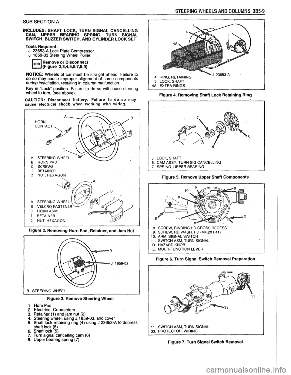
INCLUDES: SHAR LOCK, TURN SIGNAL CANCELLING
CAM, UPPER BEARING SPRING, TURN SIGNAL
SWITCH,
BULZER SWITCH, AND CYLINDER LOCK SET
Tools Required:
J 23653-A Lock Plate Compressor
J 1859-03 Steering Wheel Puller
Remove or Disconnect
(Figure
2,3,4,5,6,7,8,9)
4 RING, RETAINING 5 LOCK, SHAFT
NOTICE: Wheels of car must be straight ahead. Failure to
do so may cause improper alignment of some components
during installation, resulting in column malfunction.
Key in "Lock position. Failure to do so will cause steering
- wheel to turn, (see above).
Figure 4. Removing Shaft Lock Retaining Ring
CAUTION: Disconnect battery. Failure to do so may
cause electrical
shock when working with wiring.
B HORN PAD
C SCREWS
1 RETAINER 2 NUT, HEXAGON
A STEERING WHEEL
B VELCRO FASTENE
C HORNASM
Figure 2. Removing Horn Pad, Retainer, and Jam Nut Figure
5. Remove Upper Shaft Components
8 SCREW,
BINDING HD CROSS RECESS 9. SCREW, RD WASH. HD (M4.2X1.41)
10 ARM, SIGNAL SWITCH
11 SWITCH ASM, TURN SIGNAL
D HAZARD KNOB
Figure 6. Turn Signal Switch Removal Preparation
Figure
3. Remove Steering Wheel
1. Horn Pad
2. Electrical Connectors 3. Retaiher (1) and jam nut (2) 4. Steering wheel, using J 1859-03, and cover 5. Shait lock retaining ring (4) using J 23653-A to depress
shaft lock (5)
6. Shaft lock (5) 7. Turn signal cancelling cam (6) 8. Upper bearing spring (7) Figure 7. Turn Signal Switch Removal
Page 166 of 1825
SUB SECTION A
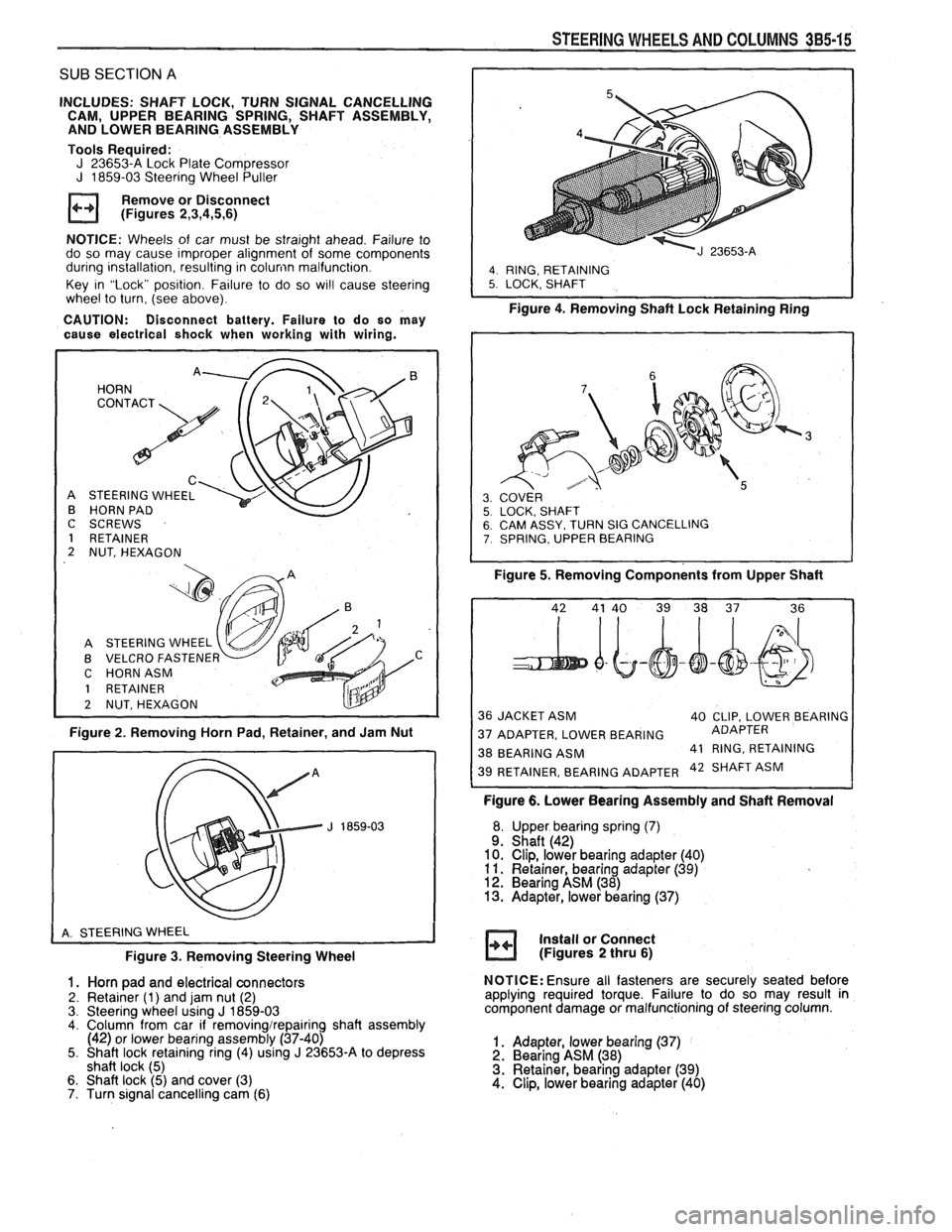
INCLUDES: SHAFT LOCK, TURN SIGNAL CANCELLING
CAM, UPPER BEARING SPRING, SHAFT ASSEMBLY,
AND LOWER BEARING ASSEMBLY
Tools Required:
J 23653-A Lock Plate Compressor J 1859-03 Steering Wheel Puller
Remove or Disconnect
(Figures
2,3,4,5,6)
NOTICE: Wheels of car must be straight ahead. Failure to
do so may cause improper alignment of some components
during installation, resulting in
colunin malfunction.
Key in "Lock" position. Failure to do so
wi!l cause steering
wheel to turn, (see above).
CAUTION: Disconnect battery. Failure to do so may
cause electrical shock when working with wiring.
HORN
C
STEERING WHEEL
HORN PAD
I
C SCREWS
1 RETAINER
2 NUT, HEXAGON
A STEERING WHEEL
B VELCRO
FASTENEF v C HORNASM
1 RETAINER
2 NUTSHEXAGON
Figure 2. Removing Horn Pad, Retainer, and Jam Nut
Figure
3. Removing Steering Wheel
1. Horn pad and electrical connectors
2. Retainer (1) and jam nut (2)
3. Steering wheel using J 1859-03 4. Column from car if removingirepairing shaft assembly
(42) or lower bearing assembly (37-40)
5. Shaft lock retaining ring (4) using
J 23653-A to depress
shaft lock (5)
6. Shaft lock (5) and cover (3)
7. Turn signal cancelling cam (6)
STEERING WHEELS AND COLUMNS 385-15
I
4. RING, RETAINING 5. LOCK. SHAFT
Figure 4. Removing Shaft Lock Retainingain;
SY. TURN SIG CANCELLING , UPPER BEARING
Figure 5. Removing Components from Upper Shaft
36 JACKET ASM
40 CLIP, LOWER BEARING
37 ADAPTER, LOWER BEARING ADAPTER
38 BEARING
ASM 41
RING, RETAINING 42 SHAFT ASM
Figure 6. Lower Bearing Assembly and Shaft Removal
Upper bearing spring
(7) Shaft (42)
Clip, lower bearing adapter (40)
Retainer, bearing adapter
(39) Bearing ASM (38) Adapter, lower bearing (37)
Install or Connect
(Figures
2 thru 6)
NOTICE: Ensure all fasteners are securely seated before
applying required torque. Failure to do so may result in
component damage or malfunctioning of steering column.
1. Adapter, lower bearing (37) 2. Bearing ASM (38)
3. Retainer, bearing adapter (39)
4. Clip, lower bearing adapter (40)