lumbar support PONTIAC FIERO 1988 Service Repair Manual
[x] Cancel search | Manufacturer: PONTIAC, Model Year: 1988, Model line: FIERO, Model: PONTIAC FIERO 1988Pages: 1825, PDF Size: 99.44 MB
Page 1166 of 1825
CONTENTS
ELECTRICAL DIAGNOSIS
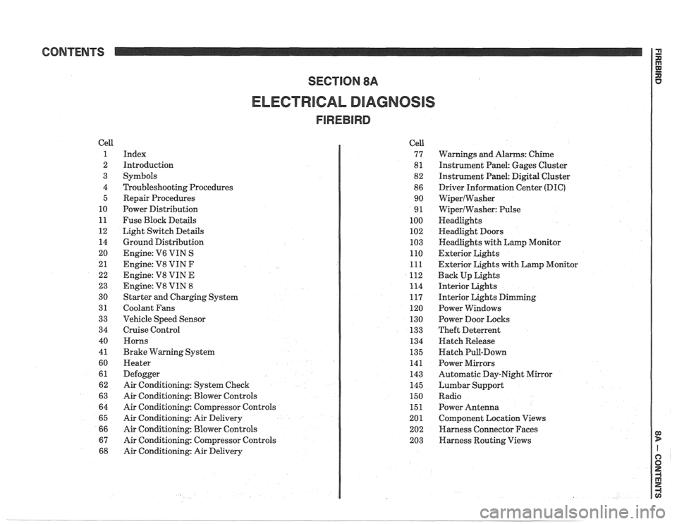
Cell
1
2
3
4 5
10
11
12 14
20
21
22
23
30
31
33
34
40
4
1
60
61
62
63
64
65
66
67
68
Index
Introduction
Symbols
Troubleshooting Procedures Repair Procedures
Power Distribution
Fuse Block Details
Light Switch Details
Ground Distribution
Engine:
V6 VIN S
Engine: V8 VIN
F
Engine: V8 VIN E
Engine:
V8 VIN 8
Starter and Charging System
Coolant Fans
Vehicle Speed Sensor
Cruise Control Horns
Brake Warning System
Heater
Defogger
Air Conditioning: System Check
Air Conditioning: Blower Controls
Air Conditioning: Compressor Controls
Air Conditioning: Air Delivery
Air Conditioning: Blower Controls
Air Conditioning: Compressor Controls
Air Conditioning: Air Delivery Cell
77
8
1
82
86 90
9
1
100
102
103
110
111
112
114
117
120
130
133
134
135
141
143
145
150
151
201 202
203
Warnings and Alarms: Chime
Instrument Panel: Gages Cluster
Instrument Panel:
Digital Cluster
Driver Information Center
(DIC)
WiperlWasher
WiperlWasher: Pulse
Headlights
Headlight Doors
Headlights with Lamp Monitor
Exterior Lights
Exterior Lights with Lamp Monitor
Back Up Lights
Interior Lights
Interior Lights Dimming
Power Windows
Power Door Locks
Theft Deterrent
Hatch Release
Hatch Pull-Down
Power Mirrors
Automatic Day-Night Mirror
Lumbar Support
Radio Power Antenna
Component Location Views
Harness Connector Faces
Harness Routing Views
Page 1168 of 1825
INDEX
Page
................... Front Marker 110-0
...................... Frontpark 110-0
......................... Hazard 110-0
........ Hazard with Lamp Monitor 111-0
..................... Headlights 100-0
........................ Doors 102-0
............ With Lamp Monitor 103-0
................. Nigh Level Stop 110-0
................... License 110.3,11 0.4
Park
........................... 110-0
............... Rear Marker 110.3,11 0.4
stop
........................... 110-1
...................... Tail 110.3,11 0.4
................ Tail with Monitor 111-2
Turn ........................... 110-0
Lights (Interior)
.............. Cargo Compartment 114-1
....................... Courtesy 114-0
.......................... Dome 114-0
...................... Glove Box 114-0
................. Lights Dimming 117-0
........................ Reading 114-0
................ Light Switch Details 12-0
.................... Mirrors (Power) 141-0
Automatic
DayINight ............ 143-0
................. Power Distribution 10-0
Radio
...................... With UK3 150-0
With
UK3 and Subwoofer
..................... Amplifier 15 0-2
Without Subwoofer Amplifier and
with
UK3 ..................... 150-5 With
Subwoofer Amplifier and
without UK3
..................
.................. Repair Procedures
Seats (Power)
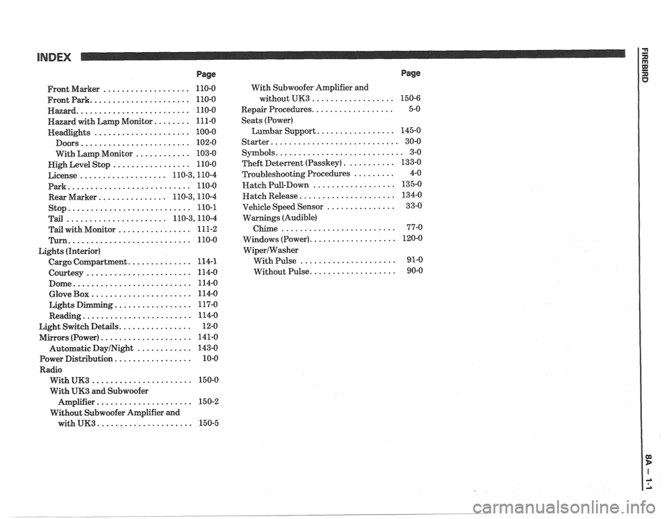
Lumbar Support
.................
Starter ............................
........................... Symbols
........... Theft Deterlent (Passkey)
......... Troubleshooting Procedures
.................. Hatch Pull-Down
..................... Hatch Release
............... Vehicle Speed Sensor
Warnings (Audible)
Chime
.........................
................... Windows (Power)
WiperIWasher
With Pulse .....................
................... Without Pulse
Page
Page 1533 of 1825
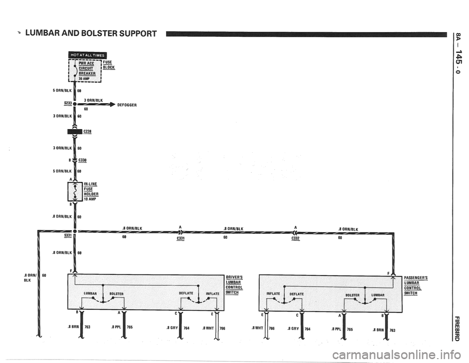
LUMBAR AND BOLSTER SUPPORT I
DEFOGGER
r:
PASSENGER'S
LUMBAR
CONTROL
SWITCH
Page 1535 of 1825
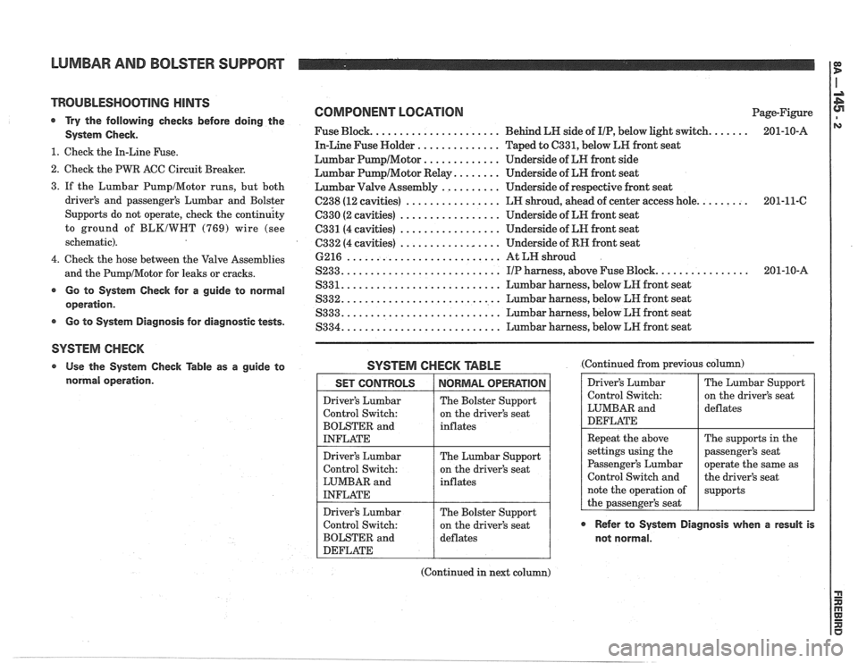
LUMBAR AND BOLSTER SUPPORT
TROUBLESHOOTING HINTS
@ Try the follovving checks before doing the
System Check.
1. Check the In-Line Fuse.
2. Check the PWR ACC Circuit Breaker.
COMPONENT LOCATION
Fuse Block. ..................... Behind LN side of IIP, below light switch.
In-Line Fuse Holder
.............. Taped to 6331, below LR front seat
Lumbar
PumpIMotor ............. Underside of LN front side
Lumbar
PumpIMotor Relay. ....... Underside of LN front seat Page-Figure
201-10-A
3. If the Lumbar
PumpIMotor runs, but both
Lumbar Valve Assembly .......... Underside of respective front seat
driver's and passenger's Lumbar and Bolster
C238 (12 cavities) ................ LN shroud, ahead of center access hole. ........ 201-11-C
Supports do not operate, check the
contin& C330 (2 cavities) ................. Underside of LM front seat
to ground of
BLKIWNT (769) wire (see C331(4 cavities) ................. Underside of LN front seat
schematic). C332 (4 cavities)
................. Underside of RH front seat
.......................... 4. Check the hose between the Valve Assemblies 6216
At
LH shroud
.......................... ............... and the PumpIMotor for leaks or cracks. S233. IIP harness, above Fuse Block. 201-10-A
.......................... r Go to System Check for a guide to normal S331. Lumbar harness, below LR front seat
.......................... operation. S332. Lumbar harness, below LR front seat
S333. .......................... Lumbar harness, below LH front seat r Go to System Diagnosis for diagnostic tests. S334. .......................... Lumbar harness, below LN front seat
SYSTEM CHECK
Use the System Check Table as a guide to SYSTEM CHECK TABLE (Continued from previous col
normal operation. Driver's Lumbar
Control Switch:
LUMBAR and
DEFLATE
Repeat the above
settings using the
Passenger's Lumbar
Control Switch and
note the operation of
the passenger's seat
@ Refer to System Diagnosis when a result is
not normal.
The Lumbar Support
on the driver's seat
deflates
The supports in the
passenger's seat
operate the same as
the driver's seat
supports SET CONTROLS
Driver's Lumbar
Control Switch:
BOLSTER and
INFLATE
Driver's Lumbar
Control Switch:
LUMBAR and
INFLATE
Driver's Lumbar
Control Switch:
BOLSTER and
DEFLATE
(Continued in next column)
NORMAL OPERATION
The Bolster Support
on the driver's seat
inflates
The Lumbar Support
on the driver's seat
inflates
The Bolster Support
on the driver's seat
deflates
Page 1536 of 1825
LUMBAR AND BOLSTER SUPPORT
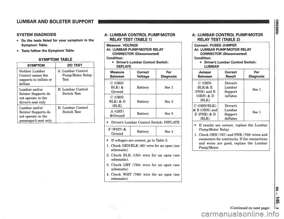
SYSTEM DIAGNOSIS A: LUMBAR CONTROL PUMPIMCITOR A: LUMBAR CONTROL PUMPIMOTOR
At: LUMBAR PUMPIMOTOR RELAY
CONNECTOR (Disconnected)
Driver's Lumbar Control Switch:
0 Driver's Lumbar Control Switch: INFLAT
0 If voltages are correct, go to Table 2.
1. Check ORNIBLK (60) wire for an open (see
schematic).
2. Check BLK (150) wire for an open (see
schematic).
3. Check GRY (764) wire for an open (see
schematic).
4. Check WHT (766) wire for an open (see
schematic).
e Do the tests listed for your symptom in the RELAY TEST (TABLE 1)
Symptom Table.
e Tests follow the Symptom Table.
SYMPTOM TABLE
SYMPTOM
Neither Lumbar
Control causes the
supports to inflate or
deflate
Lumbar and/or
Bolster Supports do
not operate in the
driver's seat only
Lumbar
and/or
Bolster Supports do
not operate in the
passenger's seat only
RELAY TEST (TABLE 2)
DO TEST
A: Lumbar Control
PumpIMotor Relay
Test
B: Lumbar Control
Switch Test
B: Lumbar Control
Switch Test
(Continued on next page)
Connect: FUSED JUMPER
At: LUMBAR
PUMPIMOTOR RELAY
CONNECTOR (Disconnected)
Condition:
e Driver's Lumbar Control Switch:
LUMBAR
For
Diagnosis
See 1
See 1
Jumper
Between
C (ORNI
BLK)& E
(PNK) and B
(ORN) & D
(BLK)
C (ORNIBLK)
& B (ORN) and
E (PNK) & D
(BLK)
0 If results are correct, replace the Lumbar
PumpIMotor Relay.
1. Check ORN (767) and PNK (768) wires and
connectors for continuity. If the connections
and wires are good, replace the Lumbar
PumpIMotor.
Correct
Result
Driver's
Lumbar Support inflates
Driver's
Lumbar Support deflates
Page 1537 of 1825
LUMBAR AND BOLSTER SUPPORT
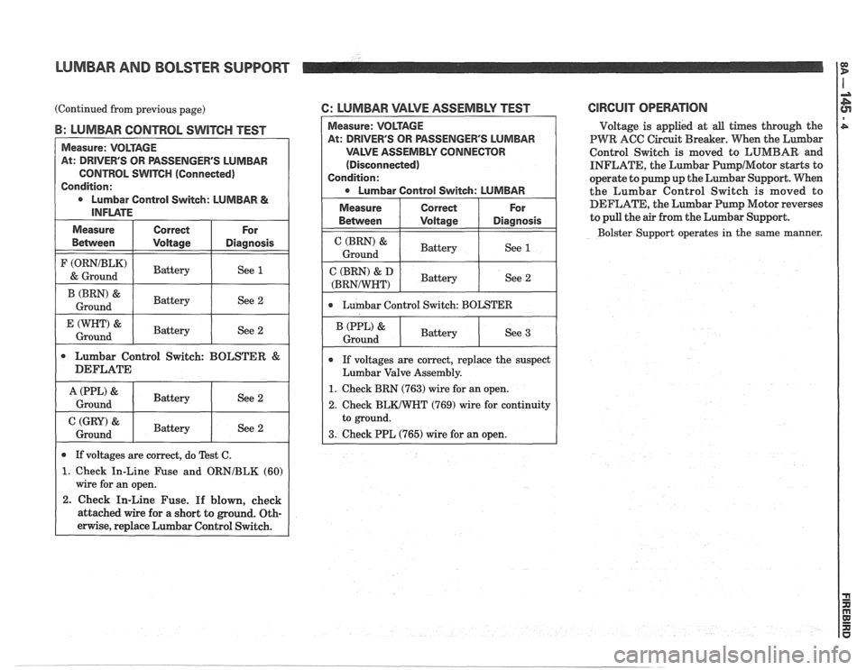
(Continued from previous page)
B: LUMBAR CONTROL SWITCH TEST
Measure: VOLTAGE
At: DRIVER'S OR PASSENGER'S LUMBAR
CONTROL
SWITCH (Connected)
Condition:
Lumbar Control
Svvitch: LUMBAR &
INFLATE
I (ORNIBLK) I ~attery ( See 1 ( & Ground
Measure
Belween
1 & 1 Battery I See 2 I
Correct
Voltage
(BRN) &
Ground
I
Lumbar Control Switch: BOLSTER &
DEFLATE
For
Diagnosis
I A(PPL) & I Battery I See 2 I Ground Battery
Ground
I I Battery I See 2 1
See 2
If voltages are correct, do Test C.
1. Check In-Line Fuse and ORNIBLK (60)
wire for an open.
2. Check In-Line Fuse. If blown, check
attached wire for a short to ground. Oth-
erwise, replace Lumbar Control Switch.
6: LUMBAR VALVE ASSEMBLY TEST CIRCUIT OPERATION
Voltage is applied at all times though the
PWR ACC Circuit Breaker. When the Lmbar
Control Switch is moved to LUMBAR and
INFLATE, the Lumbar PunapIMotor starts to
operate to pump up the Lumbar Support. When
the Lumbar Control Switch is moved to
DEFLATE, the
Lumbar Pump Motor reverses
to pull the
air from the Lumbar Support.
Bolster Support operates
in the same manner.
SSENGER'S LUMBAR
VALVE ASSEMBLY CONNECTOR
(Disconnected)
If voltages are correct, replace the suspect
Lumbar Valve Assembly.
1. Check BRN (763) wire for an open.
Page 1583 of 1825
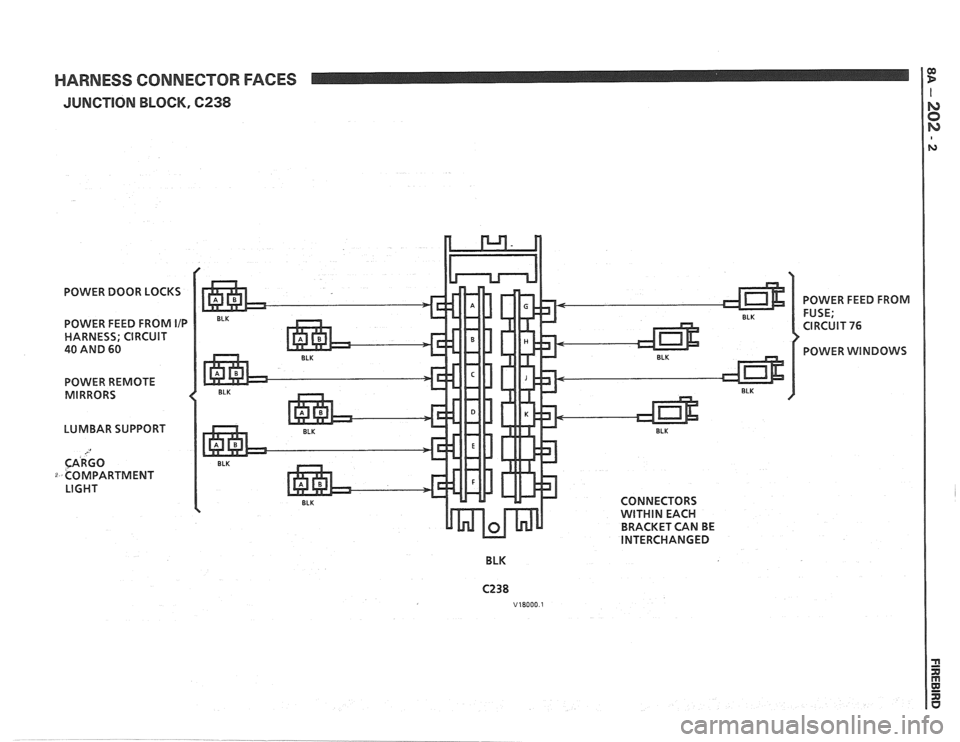
HARNESS CONNECTOR FACES
JUNCTION BLOCK, 6238
POWER DOOR LOCKS
POWER FEED FROM
IIP
HARNESS; CIRCUIT
40 AND 60
POWER REMOTE
MIRRORS
LUMBAR SUPPORT
CARGO
COMPARTMENT LIGHT CONNECTORS
WITHIN EACH
BRACKET CAN BE
INTERCHANGED
BLK POWER
FEED FROM
FUSE;
CIRCUIT
76
POWER WINDOWS
Page 1798 of 1825
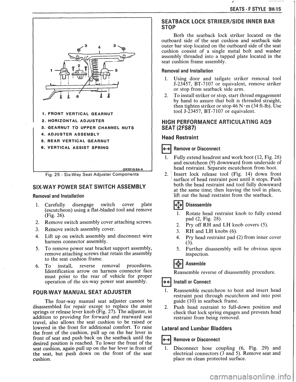
SEATS - F STYLE 9H-15
I 1. FRONT VERTICAL GEARNUT I 1 2. HORIZONTAL ADJUSTER
1 3. QEARNUT T'O UPPER CHANNEL NUTS
1 4. ADJUSTER ASSEMBLY I 5. REAR VERTICAL GEARNUT
6. VERTICAL ASSIST SPRING
Fig. 25 - Six-Way Seat Adjuster Components
SIX-WAY POWER SEAT SWITCH ASSEMBLY
Removal and Installation
1. Carefully disengage switch cover plate
(escutcheon)
using a flat-bladed tool and remove
(Fig. 26).
2. Remove
switch assembly cover attaching screws.
3. Remove switch assembly cover.
4. Lift
up on switch assembly and disconnect wire
harness connector assembly.
5. To
remove power seat bracket support assembly,
remove attaching screws that retain the assembly
to the seat cushion frame.
6. To install, reverse removal procedures.
Identification arrow on harness connector face
must point to the rear of vehicle for proper
operation of the six-way power seat assembly.
FOUR-WAY MANUAL SEAT ADJUSTER
The four-way manual seat adjuster cannot be
disassembled for repair except to replace the assist
springs or release lever knob (Fig.
27). The adjuster, in
addition to providing for forward and rearward seat
travel, also allows the seat cushion to be raised or
lowered in the front for additional comfort. To raise
the front of the cushion, pull up on the bar lever in
front of seat and push back on the
seatback until the
desired position is reached. To lower the front of the
seat cushion, again pull up on the bar lever in front of
the seat, but push down on the front of the seat
cushion.
SEATBACK LOCK %%RIMEW/SIDE INNER BAR
STOP
Both the seatback lock striker located on the
outboard side of the seat cushion and
seatback side
outer bar stop located on the outboard side of the seat
cushion consist of a single metal bolt and washer
assembly threaded into a tapped plate located in the
seat cushion frame assembly.
Removal and Installation
1.
Using door and tailgate striker removal tool
J-23457, BT-7107 or equivalent, remove striker
or stop from
seatback side arm.
2. To install striker or stop, start thread engagement
by hand to assure that bolt is threaded straight,
then tighten striker or stop 46
N.m (34 ft-lb). Use
tool J-23457, BT-7107 or equivalent.
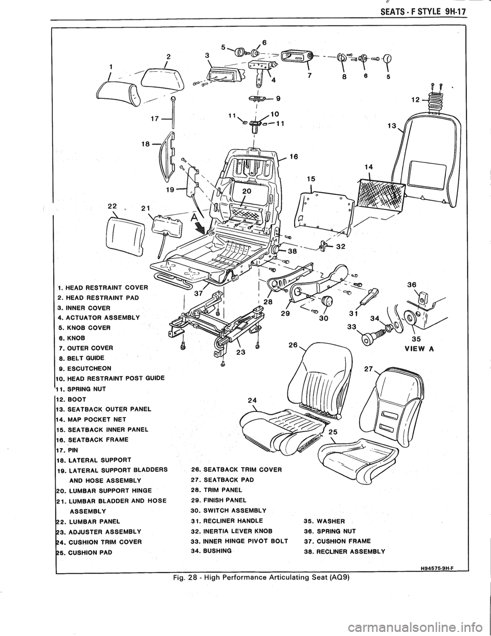
HIGH PERFORMANCE ARTICULATING AQ9
SEAT (2FS87)
Head Restraint
Remove or Disconnect
1.
Fully extend headrest and work boot (12, Fig. 28)
and escutcheon
(9) downward from underside of
head restraint. Separate escutcheon from boot.
2. Insert lock release tool (Fig. 14) down front
surface of head restraint post until it stops. Push
both the head restraint and tool fully downward
at the same time;
then leaving the tool in place,
lift out the head restraint from the seatback.
Disassemble
1. Rotate head restraint knob to fully extend
pad
(2, Fig. 28).
2. Pry
off RH and LH knob covers
(5).
3. RH and LH knobs (6).
4. Pry
head restraint pad (2) from inner cover
(3).
5. Further disassembly will be obvious upon
inspection.
+'+ Assemble [I]
Reassemble reverse of disassembly procedure.
Install or Connect
1. Reassemble escutcheon to boot and insert head
restraint post through escutcheon and into post
guide (10) in
seatback frame.
2. Push head restraint to full-down position and
check that lock spring engages and prevents head
restraint from being removed.
Lateral and Lumbar Bladders
Remove or Disconnect
1. Disconnect hose coupling (6, Fig. 29) and
electrical connectors (3 and 5). Remove seat and
place on clean protected surface.
Page 1800 of 1825
SEATS - F STYLE 9H-17
865
1. HEAD RESTRAINT COVER
2. HEAD RESTRAINT PAD
3. INNER COVER
4. ACTUATOR ASSEMBLY
5. KNOB COVER
6. KNOB
7. OUTER COVER
8. BELT GUIDE
9. ESCUTCHEON
10. HEAD RESTRAINT POST GUIDE
1 1. SPRING NUT
13. SEATBACK OUTER PANEL
14. MAP POCKET NET
15. SEATBACK INNER PANEL
16. SEATBACK FRAME
18. LATERAL SUPPORT
19. LATERAL SUPPORT BLADDERS 26. SEATBACK TRIM COVER
AND HOSE ASSEMBLY
27. SEATBACK PAD
20. LUMBAR SUPPORT HINGE 28. TRIM PANEL
21. LUMBAR BLADDER AND HOSE 29. FINISH PANEL
ASSEMBLY
30. SWITCH ASSEMBLY
2. LUMBAR PANEL 31. RECLINER HANDLE 35. WASHER
3. ADJUSTER ASSEMBLY 32. INERTIA LEVER KNOB 36. SPRING NUT
4. CUSHION TRIM COVER 33. INNER HINGE PIVOT BOLT 37. CUSHION FRAME
6. CUSHION PAD 34. BUSHING 38. RECLINER ASSEMBLY
Fig. 28 - High Performance Articulating Seat (A09)
Page 1823 of 1825
8- CHASSIS INDEX
Recommended Fluids and Lubricants ................ OB-6
Relay Rod
......................................................... 3B6-2
Remote Mirror Control
...... See Body Service Section
5H.1. 15
Repair Procedures
.......................................... 88-50
S
........................................ Scheduled Maintenance OB- 1
Seats (Power) ....................................... Lumbar Support 8A- 145-0
............................. Sequential Fuel Injection 6E3-C2- 1
Service Engine Soon Light
.................................... 8C-3
Sheet Metal and Grille
................................ Section 2C
......................................... General Description .2 C. 1
........................................... Service Procedures .2 C. 1
................................................................. Hood .2 C. 1
...................................................... Hood Hinge 2C-2
Hood Latch and Cable
...................................... 2C-2
Paint
.............................................. Color Matching 2C-5
................................................ Identification -32-6
Interior Plastic Parts ...................................... 2C-6
................................................ Shock Absorbers 3D-
1
Shoe and Lining Assembly
. Brake
............................................ 3000/3 100 Series 5B1-3
3548 Series ...................................................... 5B6-4
Side Marker Lights
.............................................. 8B-2
........ Speakers See 8A- 150-0 & Body
Manual Section
6H- 1
.................... Spark Plug Gap .. .................. 6E3-13-3
................................ Speaker and Speaker Grille 9A-9
Special Tools
............................................ Air Conditioning 1 B-3 5
Air Conditioning Compressor
................................................. Overhaul 1D1-21
........................ Automatic Transaxle AT-700-R4-64
................................................................ Brakes SF-1
Clutch ................................................................ 7C-8
................................................................ Rear 4B1-20
....................................... Rear (Borg Warner) 4B-20
........................... Driveability and Emissions .6 E. 17
................................................ Engine Cooling 6B- 14
Power Steering Pump
& Gear ...................... 3B7-17
............................................... Propeller Shaft .4 A. 12
Steering Wheels and Columns
.......................... 5-35
Specifications Automatic Transmission Unit
............................................ Repair AT-700-R4-59
..................................................... Battery 6D 1-7
................................................................ Brakes 5F-1
Bumpers
......................................................... 2B-5
Charging System
................ .. ................... 6D3-3
.............................................................. Clutch .7 (2.8
....................................... Cranking System 6D2- 1 1
Driveability and Emissions ............................ 6E-23
................................................ Engine (V-6) ..6A 2.26
Engine (V-8) .................................................. 683-28
........................................ Front Suspension 3C- 10
Power Steering Gear and Pump
.................. 3B7-18 ............................................. Propeller Shaft .4 A. 12 ........................................................ Rear Axle 4B-19 ............................ Rear Axle (Borg Warner) 4B 1- 19
Rear Suspension
.............................................. 3D-9
.......................................... Replacement Bulbs 8Br 10 .............................................. Steering Linkage 3B6-6
Steering Wheels and Columns
...................... 3B5-35
........................................ Wheel Alignments 3A-4
....................................................... Speedometer 8C-2
........................................ Speedometer (Removal) 8C-5
...................................................... Speed Sensors 8C-1
Starter ........................................ Section 6D2. 8A-30-0
............................................. Starter (Circuit) 8A-30-0
Steering Linkage ...................................... Section 3B6
....................................... General Description 3B6-1
........................ Maintenance and Adjustments 3B6-1
................................................ On-Car Service 3B6-2
..................................................... Idler Arm 3B6-4
................................................ Pitman Arm 3B6-5
.................................................... Relay Rod 3B6-3
Tie Rods
...................................................... 3B6-2
.................................................. Specifications 3B6-6
Steering, Suspension, Tires and
Wheels Diagnosis
............................................................. 3-1
Steering Wheels and Columns
............................ 3B5-1
..................................... General Information 3B5- 1
Maintenance and Adjustments
...................... 3B5-'
On-Car Service .............................. .. ........... 3B5
Checking for Accident Damage
.................. 3B5-5
Intermediate Shaft ............... .. .................... 3B5-3
Park Lock Cable .......................................... 3B5-4
Standard Column
............................. Automatic Transaxle 3B5-13
Manual Transaxle ................................. 3B5- 19
Tilt Column
.............................. Automatic Transaxle 3B5-27
.................................. Manual Transaxle 3B5-19
Unit Repair Intermediate Shaft
...................................................... Assembly 3B5-6
................................................. Special Tools 3B5-35
Torque Specifications
.................................... 3B5-35
............................................. Starting System 8A-30-0
........................................ Strut Assembly (Front) 3C-4
.................................... ..... Symbols Chart ... 8A-3-0
T
.......................................................... Tachometer 9G-1
Tail/Stop/Turn Signal/Lights .......................... 8B-2
Temperature Cable
.............................................. 112 A-
Temperature Warning Light ................................ 8C-3
Theft Deterrent (Circuit)
.............................. 8A-133-0
Tie Rods
.............................................................. 3B6-2
Tires and Wheels
........................................ Section 3E
Diagnosis
.................................................. Section 3
General Information
......................................... 3E-1
................................................... Metric Tires 3E-2
....................................... Replacement Tires .31 E-
.................................................... Tire Placard 3E-2
........................................................... Wheels 3E-2
Maintenance and Adjustments
.......................... 3E-2
.......................... Aluminum Wheel Cleaning 3E-9
............................. ......... Inflation of Tires .. 3E-3
........................................ Tire Chain Usage 3E-4
.................................................. Tire Rotation 3E-3
.............................................. Wheel Repair 3E-2
...................................... Wheel Studs/Nuts 3E-3
........................................... Service Operations 3E-4
........................ Aluminum Wheel Cleaning 3E-9
.................................... Balance Precautions 3E-7
............................ Balancing Tire and Wheel 3E-7
.............................................. Compact Spare 3E-6
........................ Correcting Nonuniform Tires 3E-8