wheel size PONTIAC FIERO 1988 Service Repair Manual
[x] Cancel search | Manufacturer: PONTIAC, Model Year: 1988, Model line: FIERO, Model: PONTIAC FIERO 1988Pages: 1825, PDF Size: 99.44 MB
Page 232 of 1825
TIRES AND WHEELS 3E-1
RES AND WHEELS
NOTICE: All wheel bolt and nut fasteners are important attaching parts in that they could affect the
performance of vital components and systems, and/or could result in major repair expense. They must be replaced
with one of the same part number or with an equivalent part if replacement becomes necessary. Do not use a
replacement part of lesser quality or substitute design. Torque values must be used as specified during reassembly
to assure proper retention of parts.
CONTENTS
Diagnosis ............................................... Section 3 Tire Repair ................................................... 3E-5
General Information .......................... ..... 3E-1 Waddle ........................................................ 3E-5
........ Replacement Tires ....................... ... 3E- 1 Measuring Wheel Runout ............................ 3E-6
P-Metric Tires ...................... .. ................... 3E-2 Spare Tire ...................................................... 3E-6 ................................................ Tire Placard 3E-2 Match Mounting ......................................... 3E-7
.......................................................... Wheels 3E-2 Balancing Tire and Wheel ............................ 3E-7
....................... Maintenance and Adjustments .............. 3E-2 General Balance Precautions 3E-7 ...................................... Wheel Repair .............................................. 3E-2 Off-Car Balancing 3E-8 .............................. Metric Wheel Nuts and Studs .................... .. 3E-3 On-Car Balancing .. ...... 3E-8
......................................... Inflation of Tires ........................................ 3E-3 Wheel Weights 3E-8 .................... Tire Rotation ........................... ...... . 3E-3 Correcting Non-Uniform Tires 3E-8 .......................... Tire Chain Usage ........................................ 3E-4 Aluminum Wheel Cleaning 3E-9 Aluminum Wheel Hub Cap ......................... 3E-9 Service Operations ..................................... 3E-4 Aluminum Wheel Porosity Repair .............. 3E-9 ......................... Wheel Removal .... .......... 3E-4 Aluminum Wheel Refinishing ...................... 3E-9 Tire Mounting and Dismounting ................. 3E-5 Wheel Nut Torque 3E-10 ......................................
GENERAL INFORMATION ~t is recommended that new tires be installed in
pairs on the same axle. If it is necessary to replace only
The tires and are one tire, it should be paired with the tire having the
designed to operate satisfactorily with loads up to and
most tread, to equalize braking traction. including the full rated load capacity when inflated to
Although they may appear different in tread
the recommended inflation pressures.
design, tires built by different manufacturers with
Correct tire pressures, wheel alignment and identical TPC specification numbers, can be
driving techniques have an important influence on tire
intermixed on the same car. life. Heavy cornering, excessive rapid acceleration, and
heavy braking will increase tire wear.
REPLACEMENT TIRES
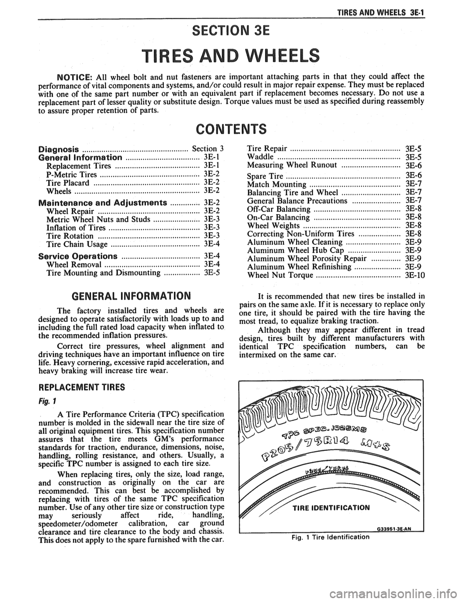
Fig. 1
A Tire Performance Criteria (TPC) specification
number is molded in the sidewall near the tire size of
all original equipment tires. This specification number
assures that the tire meets
GM's performance
standards for traction, endurance, dimensions, noise,
handling, rolling resistance, and others. Usually, a
specific TPC number is assigned to each tire size.
When replacing tires, only the size, load range,
and construction as originally on the car are
recommended. This can best be accomplished by
replacing with tires of the same TPC specification
number. Use of any other tire size or construction type
may seriously affect ride, handling,
speedometer/odometer calibration, car ground
clearance and tire clearance to the body and chassis.
This does not apply to the spare furnished with the car.
v// TIRE IDENTIFICATION
Fig. 1 Tire Identification
Page 233 of 1825
3E.2 TIRES AND WHEELS
P-METRIC SIZED TIRES
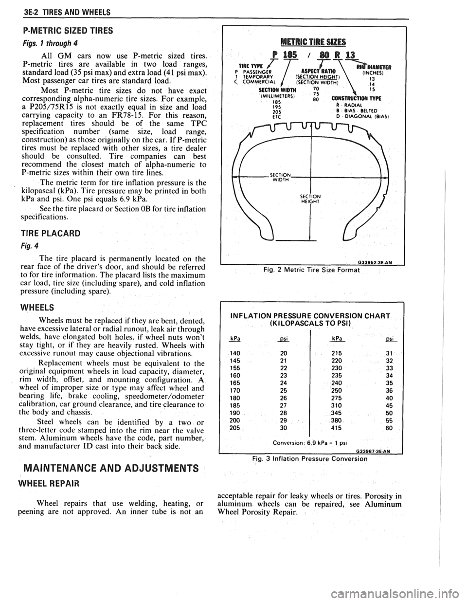
Figs. 1 through 4
All GM cars now use P-metric sized tires.
P-metric tires are available in two load ranges,
standard load
(35 psi max) and extra load (41 psi max).
Most passenger car tires are standard load.
Most P-metric tire sizes do not have exact
corresponding alpha-numeric tire sizes. For example,
a
P205/75R15 is not exactly equal in size and load
carrying capacity to an
FR78-15. For this reason,
replacement tires should be of the same TPC
specification number (same size, load range,
construction) as those originally on the car. If P-metric
tires must be replaced with other sizes, a tire dealer
should be consulted. Tire companies can best
recommend the closest match of alpha-numeric to
P-metric sizes within their own tire lines.
The metric term for tire inflation pressure is the
kilopascal
(kPa). Tire pressure may be printed in both
kPa and psi. One psi equals 6.9 kPa.
See the tire placard or Section OB for tire inflation
specifications.
TlRE PLACARD
Fig. 4
The tire placard is permanently located on the
rear
face of the driver's door, and should be referred
to for tire information. The placard lists the maximum
car load, tire size (including spare), and cold inflation
pressure (including spare).
WHEELS
Wheels must be replaced if they are bent, dented,
have excessive lateral or radial
runout, leak air through
welds, have elongated bolt holes, if wheel nuts won't
stay tight, or if they are heavily rusted. Wheels with
excessive
runout may cause objectional vibrations.
Replacement wheels must be equivalent to the
original equipment wheels in load capacity, diameter,
rim width, offset, and mounting configuration.
A
wheel of improper size or type may affect wheel and
bearing life, brake cooling,
speedometer/odometer
calibration, car ground clearance, and tire clearance to
the body and chassis.
Steel wheels can be identified by a two or
three-letter code stamped into the rim near the valve
stem. Aluminum wheels have the code, part number,
and manufacturer
ID cast into their back side.
MAINTENANCE AND ADJUSTMENTS
WHEEL REPAIR
Wheel repairs that use welding, heating, or
peening are not approved. An inner tube is not an
Fig. 2 Metric Tire Size Format
INFLATION PRESSURE CONVERSION CHART (KI LOPASCALS TO PSI)
Fig. 3 Inflation Pressure Conversion
acceptable repair for leaky wheels or tires. Porosity in
aluminum wheels can be repaired, see Aluminum
Wheel Porosity Repair.
Page 234 of 1825
TIRES AND WHEELS 3E-3
METRIC WHEEL NUTS AND STUDS
Some models use metric wheel nuts and wheel
studs. The nut will have the word "metric" stamped on
its face and the stud will have the letter
"M" stamped
into the threaded end. The word "metric" is stamped
on its head.
The thread size of the metric wheel nuts and
wheel studs are
"MI2 x 1.5". These stand for:
M = Metric
12
= Diameter in millimeters
1.5
= Millimeters per thread
If a broken stud is found, see Section 3C (Front
Suspension) or Section 3D (Rear Suspension) for
replacement procedure.
INFLATION OF TIRES
The pressure recommended for any model is
carefully calculated to give a satisfactory ride,
handling, tread life and load carrying capacity.
Tire pressure, with tires cold, (after car has set for
three hours or more, or driven less than one mile)
should be checked monthly or before any extended trip
and set to the specifications on the tire placard located
on rear face of driver's door. Tire inflation pressure is
also given in Section OB.
Valve caps or extensions should be on the valves
to keep dust and water out.
1. For sustained driving at speeds up to 85
mph (140 km/h), in countries where such
speeds are allowed by law, your tires should be set
at the pressures recommended on your tire
placard.
Sustained driving at speeds
faster than
85 mph (140 km/h), where
permitted
by law, is not advised unless
your car has special high speed tires available
from many tire dealers.
2. Tire pressures may increase as much as 6 psi
when hot.
3. Higher
than recommended pressure can cause:
o Hard ride
o Tire bruising or carcass damage
Rapid tread wear at center of tire
4. Lower
than
recommended pressure can cause:
@ Tire squeal on turns
@ Hard steering
o Rapid and uneven wear on the edges of the
tread
Tire rim bruises and rupture
e Tire cord breakage
o High tire temperatures
o Reduced handling
High fuel consumption
5. Unequal pressure on same axle can cause:
Uneven braking
o Steering lead
o Reduced handling
e Swerve on acceleration
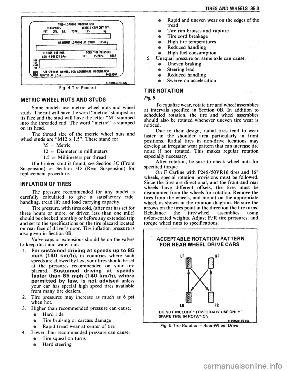
TlRE ROTATION
Fig. 5
To equalize wear, rotate tire and wheel assemblies
at intervals specified in Section OB. In addition to
scheduled rotation, the tire and wheel assemblies
should also be rotated whenever uneven tire wear is
noticed.
Due to their design, radial tires tend to wear
faster in the shoulder area particularly in front
positions. Radial
tires in non-drive
iocations may
develop an irregular wear pattern that can increase tire
noise if not rotated. This makes regular rotation
especially necessary.
After rotation, be sure to check wheel nuts for
specified torque.
On
F Carline with P245/50VR16 tires and 16"
wheels, special rotation provisions must be followed.
Since the tires are directional, and the front and rear
wheels have different offsets, the tires must be
dismounted from the wheels for rotation. Remove the
tires from the wheels, and mount on the appropriate
wheel, as shown in the rotation diagram. Be sure the
arrows on the tires point in the direction the tire turns.
Rebalance the
tire/wheel assemblies using
nylon-coated weights. Adjust
F/R tire pressures, and
torque wheel nuts to specifications.
ACCEPTABLE ROTATION PATTERN
FOR REAR WHEEL
DRIVE GARS
DO NOT INCLUDE "TEMPORARY USE ONLY" SPARE TlRE IN ROTATION
Fig. 5 Tire Rotation - Rear-Wheel Drive
Page 235 of 1825
3E.4 TIRES AND WHEELS
TIRE CHAIN USAGE
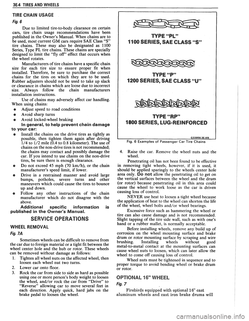
Fig. 6
Due to limited tire-to-body clearance on certain
cars, tire chain usage recommendations have been
published in the Owner's Manual. When chains are to
be used, most current
GM cars require SAE Class "S"
tire chains. These may also be designated as 1100
Series, Type PL tire chains. These chains are specially
designed to limit the "fly off' effect that occurs when
the wheel rotates.
Manufacturers of tire chains have a specific chain
size for each tire size to ensure proper fit when
installed. Therefore, be sure to purchase the correct
chains for the tires on which they are to be used.
Rubber adjusters should not be used to take up slack
or clearance in chains which are loose due to incorrect
size. Always follow the chain manufacturers
installation instructions.
Use of chains may adversely affect car handling.
When using chains:
@ Adjust speed to road conditions
@ Avoid sharp turns
@ Avoid locked-wheel braking
In general, to help prevent chain damage
to your car:
@ Install the chains on the drive tires as tightly as
possible, then tighten them again after driving
1/4 to 1/2 mile (0.4 to
0.8 kilometer). The use of
chains on the non-drive tires is not recommended;
the chains may contact and possibly damage the
car. If you intend to use chains on the non-drive
tires, be sure there is enough clearance.
e Do not exceed 45 mph (70 km/h), or the chain
manufacturer's speed limit, if lower.
@ Drive in a restrained manner and avoid large
bumps, potholes, severe turns and other
maneuvers which could cause the tires to bounce
up and down.
e Follow any other instructions of the chain
manufacturer which do not disagree with the
above.
Additional specific information is
published in the Owner's Manual.
SERVICE OPERATIONS
WHEEL REMOVAL
Fig. 7A
Sometimes wheels can be difficult to remove from
the car due to foreign material or a tight fit between the
wheel center hole and the hub or rotor. These wheels
can be removed without damage as follows:
1. Tighten all wheel nuts on the affected wheel, then
loosen each wheel nut two turns.
2. Lower car onto floor.
3. Rock the car from side to side as hard as possible
using one or more person's body weight to loosen
the wheel, and/or rock the car from
"Drive" to
"Reverse" allowing car to move several feet in
each direction. Apply quick, hard jabs on the
brake pedal to loosen the wheel.
WPE ""P"
1200 SERIES, SAE CUSS ""Up
WPE ""RP"
4800 SERIES, LUG-REINFORCED
Fig. 6 Examples of Passenger Car Tire Chains
4.
Raise the car. Remove the wheel nuts and the
wheel.
Penetrating oil has not been found to be effective
in removing tight wheels, however,
if it is used, it
should be applied sparingly to the wheels center hole
area only.
DO not allow the penetrating oil to get on
the vertical surfaces between the wheel and the drum
(or rotor) because penetrating oil in this area could
cause the wheel to work loose as the car is driven
causing loss of control.
NEVER use heat to loosen a tight wheel because
the application of heat to the wheel can shorten the life
of the wheel, wheel bolts and/or wheel bearings.
Excessive force such as hammering the wheel or
tire can also cause damage and is not recommended.
Slight tapping of the tire side wall, such as with one's
hand or a rubber mallet, is normally acceptable.
Before installing wheels, remove any build up of
corrosion on the wheel mounting surface and brake
drum or rotor mounting surface by scraping and wire
brushing. Installing wheels without good
metal-to-metal contact at the mounting surfaces can
cause wheel nuts to loosen, which can later allow the
wheel to come off causing loss of control.
Wheel nuts must be tightened in sequence and to
proper torque to avoid bending wheel or brake drum
or rotor.
0P"FIONAL 16" WHEEL
Fig. 7
Firebirds equipped with optional 16" cast
aluminum wheels and cast iron brake
drums will
Page 257 of 1825
481-4 REAR AXLE
Gear Noise
Gear noise (whine) is audible from 20 to 55 mph
under four driving conditions:
1. Light Acceleration - Accelerate slowly.
2. Road Load
- Car
driving load or constant speed.
3. Float - Using enough throttle to keep the car from
driving the engine
- car slows down gradually but
engine still pulls slightly.
4. Coast - Throttle closed and car in gear.
Bearing Noise
Bad bearings generally produce more of a rough
growl or grating sound, rather than the whine typical
of gear noise. Bearing noise frequently "wow-wows" at
bearing rpm, indicating a defective pinion or rear axle
case side bearing. This noise could easily be confused
with rear wheel bearing noise. Inspect and replace as
required.
Rear Wheel Bearing Noise
A rough rear wheel bearing produces a noise
which continues with car coasting at low speed and
transmission in neutral. Noise may diminish some by
gentle braking. With rear wheels jacked up, spin rear
wheels by hand while listening at hubs for evidence of
rough (noisy) wheel bearing.
Knock At Low Speeds
Low speed knock can be caused by worn
universal joints or a side gear hub counterbore in a case
that has worn oversize. Inspect and replace universal
joint or case and side gear as required.
Backlash Clunk
Excessive clunk with acceleration and deceleration
is caused by worn differential pinion gear shaft, excessive
clearance between axle shaft and side gear splines, exces-
sive clearance between side gear hub and counterbore in
case, worn pinion and side gear teeth, worn thrust washers
and excessive drive pinion and ring gear backlash. Re-
move worn parts and replace as required, selecting close
fitting parts when possible. Adjust pinion and ring gear
backlash.
DIAGNOSIS
1. Noise
is the same in "Light Acceleration" or
"Coast".
a. Road noise.
b. Tire noise.
c. Front wheel bearing noise.
d. Rear axle bearing noise.
2. Noise changes on a different type of road.
a. Road noise.
b. Tire noise.
3. Noise tone lowers as car speed is lowered.
a. Tire noise.
b. Front
wheel bearings and rear axle bearings.
c. Gear noise.
4. Similar noise is produced with car standing and
driving. a.
Engine noise.
b. Transmission noise.
c. Exhaust noise.
5. Vibration.
a. Rough rear axle bearing.
b. Unbalanced or damaged propeller shaft.
c. Tire unbalance.
d. Worn universal joint in propeller shaft.
e. Mis-indexed propeller shaft at pinion
flange.
f. Pinion flange runout too great.
6. A knock or click approximately every two
revolutions of the rear wheel.
a. A rear axle bearing.
b. Worn case.
7. Noise most pronounced on turns.
a. Rear axle side gear and pinion noise,
differential gear noise.
b. Axle bearings.
8. A continuous low pitch whirring or scraping
noise starting at relatively low speed.
a. All bearing noise.
9. Drive noise, coast noise or float noise.
a. Ring
and pinion gear noise.
b. Front
pinion bearing noise, coast or drive.
c. Axle bearing noise.
10. Clunk
on
acceleration or deceleration.
a. Worn
rear axle pinion shaft splines.
b. Side
gear hub counterbore in case worn
oversize.
c. Worn U-joints.
d. Excessive transmission backlash.
e. Worn axle shaft splines.
11. Chatter on turns.
a. Wrong
lube in rear axle.
b. Clutch
cone worn or spalled.
12. Clunk
or knock on rough road operation.
a. Worn suspension bushings.
PRE-REPAIR INVESTIGATION AND TROUBLE
DIAGNOSIS
A carefull diagnosis of the rear axle prior to
disassembly will often reveal valuable information as to
the extent and type of repairs or adjustments necessary.
Since frequent causes of axle noises are improper
backlash, pinion bearing pre-load, or side bearing
pre-load, or a combination, a few simple adjustments
may be all that are necessary to correct a problem.
Before disassembling the rear axle, the following
checks should be made with the results recorded and
analyzed: 1) Backlash;
2) Total Assembly Preload; 3)
Tooth Contact Pattern Test; 4) Fluid Level; and 5)
Fluid Contamination.
If axle shaft end play is excessive then check
bearings, retainer, and bolts securing backing plate.
The axle bearings could be worn and need replacement.
The four bolts or nuts securing the brake backing plate
may be loose, stripped, or missing. If the inner bearing
retainer worked loose it must be replaced.
Use care at all times to keep dirt and other foreign
matter, such as grinder dust, soot or sand, away from
differential to prevent possibility of subsequent failure.
Page 264 of 1825
REAR AXLE 4Bl-I I
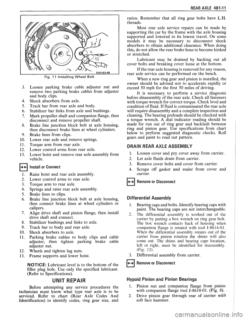
Fig. 11 Installing Wheel Bolt
Loosen parking brake cable adjuster nut and
remove two parking brake cables from adjuster
and body clips.
Shock absorbers from axle.
Track bar from rear axle and body.
Stabilizer bar links from axle and bushings.
Mark propeller shaft and companion flange, then
disconnect and remove propeller shaft.
Brake line junction block bolt at axle housing,
then disconnect brake lines at wheel cylinders.
Brake lines from clips.
Lower rear axle and remove springs.
Torque arm from rear axle.
Lower control arms from rear axle.
Lower hoist and remove rear axle assembly from
vehicle.
Install or Connect
Raise hoist and rear axle assembly.
Lower control arms to rear axle.
Torque arm to rear axle.
Springs and raise rear axle assembly.
Brake lines to clips.
Brake line junction block bolt at axle housing,
then connect brake lines at wheel cylinders or
calipers.
Align drive shaft and pinion flange, then install
drive shaft and connect.
Stabilizer bushings and links to axle.
Track bar to body and rear axle.
Shock absorbers to axle.
Parking brake cables to body clips and cable
adjuster, then tighten parking brake cable
adjuster nut.
Wheels and tighten lug nuts.
Frame supports and lower hoist.
NOTICE: Lubricant level is to the bottom of the
filler plug hole. Use only the specified lubricant.
(Refer to Specifications).
Before attempting any service procedures the
technician must know what type rear axle is to be
serviced. Refer to chart (Rear Axle Codes And
Identification) to identify codes, ring gear size, and ratios.
Remember that all ring gear bolts have
L.H.
threads.
Most rear axle service repairs can be made by
supporting the car by the frame with the axle housing
supported and lowered to its lowest travel. On some
models it may be necessary to disconnect shock
absorbers to obtain additional clearance. When doing
this, do not allow the rear brake hose to become
kinked
or stretched.
Lubricant may be drained by backing out all
cover bolts and breaking cover loose at the bottom.
If the rear axle housing is removed for any reason,
rear axle service can be performed on the bench.
When a new ring gear and pinion is installed, the
owner should be advised not to accelerate rapidly or
exceed 50 mph for the first 50 miles of driving.
It is necessary to perform a service diagnosis
before disassembly of the rear axle. Check all fasteners
with torque wrench for correct torque. Check level and
condition of fluid.
If fluid is contaminated the rear axle
will require disassembly and a complete inspection and
cleaning. The bearing preloads should be checked with
a torque wrench. A dial indicator reading should be
made for run out of ring gear and backlash between
ring and pinion gear. Use specifications from chart
below to perform suggested diagnostic checks. Roll
gears and paint to read out pattern.
DRAIN REAR AXLE ASSEMBLY
1. Loosen cover and pry cover away from carrier.
2. Let axle fluids drain from carrier.
3. Remove cover bolts and cover from carrier.
4. Scrape off gasket and sealer from cover and
carrier.
Remove or Disconnect
Differential Assembly
1. Bearing caps and bolts. Identify bearing caps with
paint. The bearing caps are not interchangeable.
2. The differential assembly is worked out of the
carrier by putting a box wrench on ring gear bolt.
The box wrench contacts back of housing when
companion
tlange is rotated with tool 3-8614-01.
When the differential assembly rotates out of the
carrier from pinion rotation the shims will also
come out. The shims and bearing caps location,
left or right, must be identified for reassembly.
(Fig. 12).
3. Differential assembly from carrier.
Remove or Disconnect
Hypoid Pinion and Pinion Bearings
1. Pinion nut and companion flange from pinion
with companion flange tool 5-8614-01. (Fig. 8).
2. Drive pinion gear through rear of carrier with
soft face hammer.
Page 270 of 1825
REAR AXLE 4B1-17
e. Assemble oiled oil seal, companion
flange, and new nut on pinion and tighten
nut to specified rotational torque while
rotating pinion forwards to seat bearing
correctly.
Important
NOTICE: If after tightening pinion nut, the
preload is excessive then the collapsible spacer
must be replaced and procedure (d) and (e)
repeated.
OPERATION OF LIMITED SLIP REAR AXLE
(CONE TYPE)
The cone-type limited-slip differential has several
definite operating characteristics. An understanding of
these characteristics is necessary as an aid to diagnosis.
During regular operation (straight ahead driving)
when both wheels rotate at equal speeds, there is an
approximately equal driving force delivered to each
wheel. When cornering, the inside wheel delivers extra
driving force causing slippage in both clutch cones.
Consequently, the operational life of the limited slip
unit is dependent upon equal rotation of both wheels
during straight ahead operation. If wheel rotation for
both rear wheels is not equal during straight ahead
operation, the limited-slip unit will constantly be
functioning as if the vehicle were cornering. This will
impose constant slippage on the clutch cones and will
eventually lead to abnormal wear on the clutch cones.
Therefore, it is important that there be no excessive differences in
the rear wheel tire sizes, air pressures, or
tire wear patterns. One indication of this condition is
"swerving on acceleration." If swerving on
acceleration is encountered, check the rear wheels for
different tire size, air pressure, or excessively different
wear patterns, and tread depths, before proceeding into
an overhaul operation.
Checking Limited-Slip Function
1. Place transmisison in Park position.
2. Raise rear of vehicle until one wheel is off the
ground, remove one wheel and tire assembly.
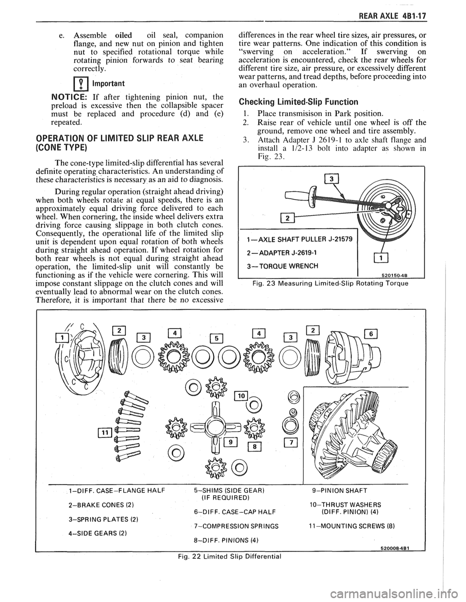
3. Attach Adapter
J 2619-1 to axle shaft flange and
install a 1/2-13 bolt into adapter as shown in
Fig. 23.
1 -AXLE SHAFT PULLER J-21579
3-TORQUE WRENCH
Fig.
23 Measuring Limited-Slip Rotating Torque
- - 1-DIFF. CASE-FLANGE HALF 5-SHIMS (SIDE GEAR) 9-PINION SHAFT
(IF REQUIRED)
2-BRAKE CONES
(2) 10-THRUST WASHERS
6-DIFF. CASE-CAP HALF (DIFF. PINION) (4)
3-SPRING PLATES (2) 7-COMPRESSION SPRINGS 11
-MOUNTING SCREWS (8) 4-SIDE GEARS (2) 8-DIFF. PINIONS (4)
Fig. 22 Limited Slip Differential
Page 271 of 1825
484-18 REAR AXLE
4. With transmission in park and both wheels and
tires clear of ground, (wheels will r~tate in opp-
osite directions), measure torque required to
rotateaxle shafts with a torque
wrenchattached
to J 2619-1. If the torque reading is less than
48 N.m (35 1b.ft.) the unit should be disassembled
and repaired as required.
5. Reinstall wheel and tire assembly.
Disassemble
Limited Slip Differential.
1. Remove ring gear bolts.
NOTICE: Left hand threaded ring gear bolts.
2. Tap
ring gear off differential housing with soft
face hammer.
NOTICE: Mark differential case halves with
alignment mark before disassembly because they
could be assembled
180" off from original position.
3. Remove 8 screws holding differential housing
halves together and separate halves. 4.
Remove pinion shaft, 4 differential pinions,
thrust washers side gears, side gear shims
(if
required), spring plates, and compression springs
from housing. Discard compression springs. New
springs are required for assembly.
5. Mark each cone during disassembly to ensure
that the same brake cone will be assembled with
the same case as originally assembled. If shims
are used they must be marked so that they will be
assembled in original case half.
6. If differential bearings are damaged remove with
tool J-22888-D. (Fig. 15).
Inspect
Disassemble
The inspection procedures for the positraction
differential are the same as those for the standard
rear axle except for the side gear positioning
shims. The side gear positioning shims are used
to control case size.
1. The shims should be free of cracks, nicks, or
burrs.
2. Assemble brake cones in case and measure to
determine correct shim size. Measure the
distance from case mating surface to flat surface
on brake cone when fully seated. Select shim size
from chart below.
DISASSEMBLY INSPECTION CHART
Distance Measured mm (ins) Size
Shim Required
29.51/29.34 (1.162/1/155) no shim required.
29.64/29.54 (1.167/1.163) 0.13 (.005) shim required.
29.77D9.67 (1.172/1.168) 0.25 (.010) shim required.
Assemble
Limited Slip Differential
1.
Lubricate both sides of pinion thrust washers,
pinion bores and differential pinion shafts with
specified rear axle lube before assembling.
2. Install the 4 pinions and spherical thrust washers.
3. Replace original brake cone, shim if required, and
side gear in cap half of differential case. For shim
selection, if needed, refer to Disassembly
Inspection Chart. Apply mixture of molybdenum
disulphide and specified axle oil to face of side
gear.
NOTICE: Do not 1.eplace cone or case
independently. They must be replaced as a unit
together.
4. Install spring
plate on side gear with convex side
towards flange half.
5. Assemble differential pinion shaft, pinions, and
spherical thrust washers into cap half of
differential case with pinions meshing with side
gear. 6.
Install three new concentric thrust springs
through the center of the pinion shaft spider.
7. Assemble second spring plate and springs with
cgnvex side towards springs.
8. Coat other side gear face with molybdenum
disulphide and axle lubricant and install side gear
shim if required. Install brake cone on spring
plate.
9. Install
flange half of case on top of assembly with
oil channels aligned.
10. Install
two bolts through cases
180" apart and
tighten finger tight.
11. Axle shafts are used to align the side gear and
brake cone splines. Put a clamp on one axle shaft
so 75 mm (3 inches) extends beyond clamp.
Install differential housing onto axle shaft splines,
flanged half first.
12. Install other axle shaft through cap side of
differential case and align side gear and cone
splines.
13. Install remaining
bolts and tighten to specified
torque.
14. Install
ring gear and tighten bolts to specified
torque.
Page 276 of 1825
REAR AXLE 4B-3
Noise which originates in other places cannot be
corrected by adjustment or replacement of parts in the
differential. It should also be remembered that rear
axle gears, like any other mechanical device, are not
absolutely quiet and should be accepted as being
commercially quiet unless some abnormal noise is
present.
To make a systematic check for axle noise under
standard conditions, observe the following:
1. Select a level smooth asphalt road to reduce tire
noise and body drumming.
2. Check rear axle lubricant to assure correct level,
then drive car far enough to thoroughly warm up
rear axle lubricant.
3. Note speed and RPM at which noise occurs. Then
stop car and with automatic transmission in neutral,
run engine slowly up and down through engine speeds, corresponding to car speed at which noise
was most pronounced, to determine if it is caused by
exhaust, muffler roar or other engine conditions.
4. Tire noise changes with different road surfaces,
but rear axle noise does not. Temporarily
inflating all tires to approximately 50 pounds
pressure for
test purposes only will materially
alter noise caused by tires, but will not affect noise
caused by rear axle. Rear axle noise usually stops
when coasting at speeds under 30 miles per hour;
however, tire noise continues, but with lower
tone, as car speed is reduced. Rear axle noise
usually changes when comparing acceleration
and coast, but tire noise remains about the same.
Distinguish between tire noise and rear axle noise
by noting if noise varies with various speeds or
sudden acceleration and deceleration; exhaust
and axle noise show variations under these
conditions while tire noise remains constant and
is more pronounced at speeds of 20 to 30 miles
per hour. Further check for tire noise by driving
car over smooth pavements or dirt roads (not
gravel) with tires at normal pressure. If noise is
caused by tires, it will noticeably change or
disappear and reappear with changes in road
surface.
5. Loose or rough front wheel bearings will cause
noise which may be confused with rear axle
noises; however, front wheel bearing noise does
not change when comparing drive and coast.
Light application of brakes while holding car
speed steady will often cause wheel bearing noise
to diminish, as this takes some weight off the
bearing. Front wheel bearings may be easily
checked for noise by jacking up the wheels and
spinning them, also by shaking wheels to
determine if bearings are loose.
6. Rear suspension rubber bushings and spring
insulators dampen out rear axle noise when
correctly installed. Check to see that no metallic
contact exists between the spring and spring
opening in frame or between upper and lower
control arm bushings and frame or axle housing
brackets.
Metal-to-metal contact at those points
may result in telegraphing road noise and normal axle
noise which would not be objectionable if
dampened by bushings.
AXLE NOISES
Gear Noise
After the noise has been determined as being in
the
axle by following the above appraisal procedure,
the type of axle noise should be determined to aid in
maki~~g repairs if necessary.
Gear noise (whine) is audible from 20 to
55 mph
under four driving conditions:
1. Drive - Acceleration or heavy pull.
2. Road Load - Car driving load or constant speed.
3. Float
- Using
enough throttle to keep the car from
driving the engine
- car slows down gradually but
engine still pulls slightly.
4. Coast
- Throttle closed and car in gear. Gear
noise most frequently has periods where noise is
more prominent, usually 30 to 40 mph and 50 to
55 mph.
Bearing Noise
Bad bearings generally produce more of a rough
growl or grating sound, rather than the whine typical
of gear noise. Bearing noise frequently "wow-wows" at
bearing rpm, indicating a defective pinion or rear axle
case side bearing. This noise could easily be confused
with rear wheel bearing noise. Inspect and replace as
required.
Rear Wheel Bearing Noise
A rough rear wheel bearing produces a noise
which continues with car coasting at low speed and
transmission in neutral. Noise may diminish some by
gentle braking. With rear wheels jacked up, spin rear
wheels by hand while listening at hubs for evidence of
rough (noisy) wheel bearing.
I(noclc At Low Speeds
Low speed knock can be caused by worn
universal joints or a side gear hub counterbore in a case
that has worn oversize. Inspect and replace universal
joint or case and side gear as required.
Baclclash Clunk
Excessive clunk with acceleration and
deceleration is caused by worn differential pinion shaft,
excessive clearance between axle shaft and side gear
splines, excessive clearance between side gear hub and
counterbore in case worn pinion and side gear teeth,
worn thrust washers and excessive drive pinion and
rear gear backlash. Remove worn parts and replace as
required, selecting close fitting parts when possible.
Adjust pinion and ring gear backlash.
REAR AXLE STANDARD AND LIMITED-SLIP
1. Noise is the same in "Drive" or "Coast".
a. Road noise.
b. Tire noise.
c. Front wheel bearing noise.
Page 277 of 1825
4B-4 REAR AXLE
d. Incorrect driveline angle.
Noise changes on a different type of road.
a. Road noise.
b. Tire noise.
Noise tone lowers as car speed is lowered.
a. Tire noise.
Similar noise is produced with car standing and
driving.
a. Engine noise.
b. Transmission noise.
Vibration. a. Rough rear wheel bearing.
b. Unbalanced
or damaged propeller shaft.
c. Tire unbalance.
d. Worn
universal joint in propeller shaft.
e. Incorrect driveline angle.
f. Mis-indexed propeller shaft at pinion
flange.
g. Pinion
flange
runout too great.
A knock or click approximately every two
revolutions of the rear wheel.
a. A rear wheel bearing.
Noise most pronounced on turns.
a. Rear
axle side gear and pinion noise.
A continuous low pitch whirring or scraping
noise starting at relatively low speed.
a. Pinion bearing noise.
Drive noise, coast noise or float noise.
a. Ring and
pinion gear noise.
Clunk on acceleration or deceleration.
a. Worn rear
axle pinion shaft in case or side
gear hub counterbore in case worn oversize.
b. Insufficient
lubrication on propeller shaft
slip yoke.
c. Worn U-joints on
propeller shaft. Front or
rear.
Groan in "Forward" or "Reverse".
a. Wrong
or contaminated lube in rear axle.
b. Worn bushings.
Chatter on turns.
a. Wrong
or contaminated lube in rear axle.
b. Clutch
cone worn and/or
spring(s) worn.
Clunk or knock on rough road operation.
a. Excessive end play of axle shafts to
differential cross shaft.
b. Worn bushings.
PRE-REPAIR INVESTIGATION AND TROUBLE
DIAGNOSIS
A careful1 diagnosis of the rear axle prior to
disassembly will often reveal valuable information as to
the extent and type of repairs or adjustments necessary.
Since frequent causes of axle noises are improper
backlash, pinion bearing pre-load, or side bearing
pre-load, or a combination, a few simple adjustments
may be all that are necessary to correct a problem.
Therefore, before removing the rear axle from the
housing, the following checks should be made with the
results recorded and analyzed:
1) Backlash; 2) Total Assembly
Preload; 3) Tooth Contact Pattern Test;
4)
Fluid Level; and 5) Fluid Contamination.
Use care at all times to keep dirt and other foreign
matter, such as grinder dust, soot or sand, away from
differential to prevent possibility of subsequent failure.
The pinion and ring gear must be completely
assembled, installed and all pre-load and backlash
adjustments completed prior to the start of this method
of pinion depth setting. The following procedure can
be used in place of the gage method of pinion depth
setting.
Gear Tooth Nomenclature
The side of the ring gear tooth which curves
outward, or is convex, is referred to as the "drive" side.
The concave side is the "coast" side. The end of the
tooth nearest center of ring gear is referred to as the
"toe" end. The end of the tooth farthest away from the
center is the "heel" end. Toe end of tooth is smaller
than heel end.
It is very important that tooth contact be tested
before the rear axle carrier assembly is disassembled.
Variations in the carrier or pinion rear bearing may
cause the pinion to be too far away from, or close to,
the ring gear. Thus, the tooth contact must be tested
and corrected, if necessary, or the gears may be noisy.
Tooth Contact Pattern Test
1. Wipe oil out of carrier and carefully clean each
tooth of ring gear.
2. Use gear marking compound part number
1052351 or equivalent and apply this mixture
sparingly to all ring gear teeth, using a medium
stiff brush. When properly used, the area of
pinion tooth contact will be visible when hand
load is applied.
3. Tighten bearing cap bolts to 75
N.m (55 lb. ft.).
4. Expand
brake shoes using parking brake cables
until a torque of 54 to
70 N-m (40-50 lb. ft.) is
required to turn the pinion.
A test made without loading the gears will not
give a satisfactory pattern. Turn pinion flange
with wrench so that ring gear rotates one full
revolution, then reverse rotation so that ring gear
rotates one revolution in opposite direction.
5. Observe
pattern on ring gear teeth and compare
with Fig. 3.
Effects of Increasing Load on Teeth Contact
Pattern
When "load" on ring and pinion gear is
increased, such as when car is accelerated forward
from standstill or from normal drive, the tooth contact
will tend to spread out and, under very heavy load, will
extend from near toe to near heel on the drive side. The
entire contact also tends to shift toward heel under
increasingly heavier loads and will become somewhat
broader with respect to tops and bottoms of teeth. The
patterns obtained by this tooth contact pattern test
approximate a light load and, for this reason, they will
extend only about halfway.