fuel cap release PONTIAC FIERO 1988 Service Repair Manual
[x] Cancel search | Manufacturer: PONTIAC, Model Year: 1988, Model line: FIERO, Model: PONTIAC FIERO 1988Pages: 1825, PDF Size: 99.44 MB
Page 22 of 1825

MAINTENANCE AND LUBRICATION OB-5
Throttle linkage inspection -- Inspect for inter-
ference, binding, damaged or missing parts.
Engine drive belts inspection - Inspect all
belts for cracks, fraying and wear. Adjust or replace as
needed.
Rear axle service (if equipped) - Check gear
lubricant level and add if needed. For cars equipped with a
limited slip rear axle, fluid does not require changing
(except Caprice and Corvette
- change fluid and required
additive at first
7,500 miles (12 500 km). See your
Owner's Manual or "Recommended Fluids
& Lubricants
Chart" in this section.
IF YOU USE YOUR GAR TO PULL A TRAILER,
CHANGE GEAR LUBRICANT EVERY 7,500 MILES
(12 500 KM).
NOTICE: A large loss in this system may indicate a
problem. Have it inspected and repaired at once.
Power antenna - Clean and then lubricate power
antenna mast. The proper lubricant as shown in Figure
OB-2 should be used.
AT LEAST ONCE A YEAR
Lap and shoulder belts condition and opera-
tion
- Inspect belt system, including webbing, buckles,
latch plates, retractors, guide loops and anchors.
Moveable head restraint operation - On cars
with moveable restraints, make sure restraints stay in the
desired position. (See adjustment instructions in your
Owner's Manual.)
Seatback latch and recliner operation on
cars equipped
with recliner seat --- Be sure seat-
backs latch on those cars with folding seats using mechan-
ical latches. Make sure the recliner is holding by pushing
and pulling on the top of the
seatback while it is reclined.
See your Owner's Manual for seat operating information.
Spare tire and jack storage- Be alert to rattles
in rear of car. Make sure the space tire, all jacking equip-
ment, any tire inflator and any covers or doors are securely
stowed at all times. Oil jack ratchet or screw mechanism
after each use.
Key lock service - Lubricate key lock cylinder at
least annually.
Body lubrication service - Lubricate all body
door hinges including the tailgate or hatchback lid (if
equipped). Also lubricate the body hood, fuel door and
rear compartment hinges and latches including interior
glove box and counsel doors, and any folding seat
hardware.
"Fansmissionltransaxle neutral or clutch
starl switch operation
CAUnON: Before pedorming the follow-
ing safety switch check, be sure to have
enough room around the car. Then, firmly
apply both the parking brake (see your
Owner's Manual for procedure) and the
regular brakes. Do not use the accelerator pedal.
If the engine
starls, be ready to turn
off the ignition promptly. Take these pre-
cautions because the car could move
without warning and possibly cause per-
sonal injury or properly damage. On auto-
matic transmissionltransaxle cars, try to
starl the engine in each gear. The starler
should crank only in "Park" or "Neutral."
On manual transmissionltransaxle cars,
place the
shiR lever in "Neutral," push the
clutch halfway and try to starl. The starler
should crank only when the clutch is fully
depressed.
Steering column lock operation
- While
parked, try to turn key to "Lock" in each gear range. The
key should turn to "Lock" only when gear is in "Park" on
automatic or "Reverse" on manual
transmissionltransax-
le. On cars with key release lever, try to turn key toULock"
without depressing the lever. The key should turn to
"Lock" only with the key lever depressed. On all vehicles,
the key should come out only in "Lock."
Parking brake and transmissionltransaxle
"Park" mechanism operation
CAUT1ON:Before checking the holding
ability of the parking brake and automatic
transmissionltransaxle "Park" mecha-
nism, park on a fairly steep hill with
enough room for movement in the down-
hill direction. To reduce the risk of person-
al injury or property damage, be prepared
to apply the regular brakes promptly if the
car begins to move.
To check the parking brake, with the engine running and
transmission/transaxle in "Neutral." slowly remove foot
pressure from the regular brake pedal (until the car is held
by only the parking brake).
To check the automatic transmissionltransaxle "Park"
mechanism holding ability, release all brakes after shift-
ing the transmissionltransaxle to "Park."
ljnderbody flushing - At least every spring,
tlush from the underbody with plain water any corrosive
materials used for ice and snow removal and dust control.
Take care to thoroughly clean any areas where mud and
other debris can collect.
Sediment packed in closed areas
of the vehicle should be loosened before being flushed.
Engine cooling system service - Inspect
coolant and freeze protection. If dirty or rusty, drain, flush
and refill with new coolant. Keep coolant
at the proper
mixture as specified in your Owner's Manual. This pro-
vides proper freeze protection. corrosion inhibitor level
and engine operating temperature. Inspect hoses and re-
place if cracked. swollen or deteriorated. Tighten hose
clamps. Clean outside of radiator and air conditioning
condensor. Wash radiator filler cap and neck.
To help
ensure proper operation. a pressure test of both the cooling
system and cap is also recommended. (See maintenance
schedule charts in Figure
OB-l for the recommended
coolant change interval.)
Page 433 of 1825

6C-2 ENGINE FUEL
components such as the accelerator pumps and/or
air-fuel mixture leaning effects.
Various types and concentrations of alcohols are
used in commercial gasoline. Some alcohols are more
detrimental to fuel system components than others. If
an excessive amount of alcohol in the fuel is suspected
as the cause of a driveability condition, the following
procedure may be used to detect the presence of
alcohol in the fuel.
In this procedure, water is used to
extract the alcohol from the fuel. However, the specific
type of alcohol is not determined.
The fuel sample should be drawn from the
bottom part of the tank so that any water, if already
present, can be detected. The sample should be bright
and clear. If the sample appears cloudy or
contaminated with water as indicated by a water layer
in the bottom part of the sample, this procedure should
not be used. The fuel system should then be cleaned
(See Fuel System Cleaning).
Testing Procedure
1. Using a 100 ml cylinder with 1 ml graduation
marks, fill with fuel to the 90 ml mark.
2. Add 10 ml of water to bring the total fluid volume
to 100 ml and install a stopper.
3. Shake vigorously for 10 to 15 seconds.
4. Carefully loosen stopper to release pressure.
5. Close the stopper and shake vigorously again for
10 to 15 seconds.
6. Carefully loosen
stopper to release pressure.
7. Put the graduated cylinder on a level surface for
approximately 5 minutes to allow adequate liquid
separation.
If alcohol is present in the fuel, the volume of the
lower layer, which would now contain alcohol and
water will be greater than 10 ml. For example, if the
volume of the lower layer is increased to 15 ml, it
would indicate at least 5 percent alcohol in fuel. The
actual amount of alcohol may be somewhat greater
because this procedure does not extract all of the
alcohol from the fuel.
FUEL METERING
Throttle Body lnjection
(TBI)
With Throttle Body Injection (TBI), an injection
unit is placed on the intake manifold where the
carburetor is normally mounted. The TBI unit is
computer controlled and supplies the correct amount
of fuel during all engine operating conditions. See
Section 6E2 for information relative to operation and
diagnosis of TBI units.
Port Fuel lnjection
The ECM is in complete control of this fuel
delivery system during all driving conditions.
The intake manifold is used only to let air into the
engine. Fuel is injected by separate injectors that are
mounted over the intake valve.
With the Port Injection System, there is no need
for a Thermac, EFE, Map Sensor, Baro Sensor, A.I.R.
System, or Dual Bed Converter. This
system provides better cold driveability,
lower exhaust emissions and better throttle response.
In Sequential Fuel Injection systems (SFI),
injectors turn on at every crankshaft revolution. The
ECM controls the injector "on" time so that the
correct amount of fuel is metered, depending on
driving conditions.
Two interchangeable
"0" rings are used on the
injector that must be inspected when the injectors are
removed. Check
"0" rings for cuts or other type of
damage and replace as necessary.
The air cleaner is remotely mounted near the
radiator. It is connected to the intake manifold by air
intake ducting.
Also, mounted between the air cleaner and
intake, are the mass air flow sensor and throttle body.
Cold driveability characteristics are greatly
improved with the aid of an engine coolant supply to
the throttle body for rapid warm up.
The throttle body design uses an integral Idle Air
Control to govern idle speed and a Throttle Position
Sensor (TPS). The IAC and TPS are both controlled
by the ECM.
A large diameter fuel rail is attached to the intake
manifold and supplies fuel to all the injectors.
A fuel pressure tap is located on the rail for quick
pressure checks.
Fuel is recirculated through the rail continually
while the engine is running. This removes air and
vapors from the fuel as well as keeping the fuel cool
during hot weather operation.
A fuel pressure regulator is mounted on the fuel
rail. It maintains a constant 36 psi pressure across the
injectors under all operating conditions. It is
accomplished by controlling the amount of fuel that is
recirculated back to the fuel tank, based on engine
demand.
The pressure regulator also uses an
"0" ring for
attachment. The
"0" ring used is the same one that is
used for the injectors.
Some engines also have an accumulator that is
located in the fuel feed line near the cowl area. It is used
to dampen the vibration that is caused by the
pressurized fuel and the pulsing of the injector.
See Section 6E3 for more information and
diagnosis.
Fuel Feed and Return Pipe
When replacing fuel feed and return pipes, always
replace them with welded steel tubing meeting GM
Specification
124M, or its equivalent. The replacement
pipe must use the same type of fittings as the original
pipes to ensure the integrity of the connection.
NOTICE: Do not replace fuel pipe with fuel hose
or any other type of tubing such as copper or
aluminum. Only tubing meeting the 124M
specification is capable of meeting all the pressure
and vibration characteristics necessary to ensure
the durability standard required.
Always check and replace any
"0" rings or
washers that appear damaged.
Page 472 of 1825

IGNITION SYSTEM 6B4-3
flash-over, which causes engine misfiring. Do not
mistake corona discharge for flash-over, or a shorted
insulator. Corona is a steady blue light appearing
around the insulator, just above the shell crimp. It is
the visible evidence of a high-tension field and has no
effect on ignition performance. Usually it can be
detected only in darkness. This discharge may repel
dust particles, leaving a clear ring on the insulator just
above the shell. This ring is sometimes mistakenly
regarded as evidence that combustion gases have blown
out between shell and insulator.
lgnition Switch
The mechanical switch is located in the steering
column on the right hand side just below the steering
wheel. The electrical switching portion of the assembly
is separate from the key and lock cylinder. However,
both are synchronized and work in conjunction with
each other through the action of the actuator rod
assembly.
For a complete explanation of the key and lock
cylinder, and the actuator rod assembly, see
STEERING, Section
38. See Section 8 for electrical
switching.
DIAGNOSIS
IGNITION SYSTEM
Spark Plugs
Worn or dirty plugs may give satisfactory
operation at idling speed, but at higher RPM they
frequently fail. Faulty plugs are indicated in a number
of ways: poor fuel economy, power loss, loss of speed,
hard starting and generally poor engine performance.
Spark plugs may also fail due to carbon fouling,
excessive gap, or a broken insulator. Fouled plugs may
be indicated by black carbon
deposits. The black deposits are usually the result of
slow-speed driving and short runs, where sufficient
engine operating temperature is seldom reached. Worn
pistons, rings, faulty ignition, over-rich carburetion
and spark plugs which are too cold will also result in
carbon deposits.
Excessive gap wear, on plugs of low mileage,
usually indicates the engine is operating at high speeds,
or loads that are consistently greater than normal, or
that a plug which is too hot is being used. Electrode
wear may also be the result of plug overheating,
causcd
by combustion gases leaking past the threads due to
insufficient torquing of the spark plug. Excessively lean
carburetion will also result in accelerated electrode
wear.
Broken insulators are usually the result of
improper installation, or carelessness when regapping
the plug. Broken upper insulators usually result from
a poor fitting wrench, or an outside blow. The cracked
insulator may not show up right away, but will as soon
as oil or moisture penetrates the crack. The crack is
usually just below the crimped part of shell and may
not be visible.
Broken lower insulators usually result from
carelessness when regapping and generally are visible.
This type of break may result from the plug operating
too "hot", which may happen in periods of high-speed
operation or under heavy loads. When regapping a
spark plug, always make the gap adjustment by
bending the ground (side) electrode. Spark plugs with
broken insulators should always be replaced.
HE1 Distributor
See Unit Repair for distributor disassembly, test
and reassembly of individual distributor components,
when the distributor is removed from the vehicle. See
On-Car Service for distributor removal and installation
and for component removal with distributor in car. See
Section 6E for
HE1 and EST diagnosis.
SERVICE PROCEDURES
IGNITION SYSTEM
Distributor Ignition
NOTICE: This procedure is generally true for
most carlines. Where procedure is different, or
where additional information is required, see
"ON-CAR SERVICE" for specific
carline.
HE1 DISTRIBUTOR
Service Precautions
1. When making compression checks, disconnect
the ignition switch feed wire at the distributor.
When disconnecting this connector,
do not use
a screwdriver or tool to release the locking tab, as
it may break.
2. No periodic lubrication is required. Engine oil
lubricates the lower bushing and an oil-filled
reservoir provides lubrication for the upper
bushing. 3.
The tachometer (TACH) terminal is next to the
ignition switch (BAT) connector on the
distributor cap.
NOTICE: The tachometer terminal must
NEVER be allowed to touch ground, as damage
to the module and/or ignition coil can result.
Some tachometers currently in use may NOT be
compatible with the High Energy Ignition System.
Consult the manufacturer of the tachometer if
questions arise.
4. Dwell adjustment is controlled by the module,
and cannot be adjusted.
5. The material used to construct the spark plug
cables is very soft. This cable will withstand more
heat and carry a higher voltage, but scuffing and
cutting become easier. The spark plug cables
must be routed correctly to prevent
chafing or
cutting. See Spark Plug Section. When removing
Page 744 of 1825

DRIVEABILITY AND EMISSIONS 2.8L (VIN S) 6E3-C2-9
26 FUEL PRESSURE CONNECTION ASSEMBLY
27 SEAL - FUEL PRESSURE CONNECTION ASSEMBLY
28 CAP - FUEL PRESSURE CONNECTION ASSEMBLY
55 FUEL BLOCK
Figure C2-10 Fuel Pressure Connection Assembly
FUEL BLOCK AND SEAL
Figure CZ-I 1
Remove or Disconnect
1. Negative battery terminal.
2. Engine components above fuel block.
I O-RING -FUEL INLET 2 O-RING . FUEL RETURN 11 FUEL RAlL ASSEMBLY 55 FUEL BLOCK 56 SEAL -FUEL BLOCK 57 SCREW ASSEMBLY - FUEL BLOCK ATTACHING 55 1461-6E
Figure C2-11 Fuel Block Assembly
Clean
@ Fuel block (55) and adiacent fuel line
connections with
AC ~elco X-30A or
equivalent.
3. Fuel inlet and return lines, and O-ring seals (1)
and (2).
- Discard O-ring seals.
4. Fuel block attaching screw assemblies
(57).
5. Fuel block (55) and seal (56). Discard seal.
FUEL RAlL
REL
85 INJECTOR -PORT
87 CLIP-INJECTOR RETAINER
Figure C2-12 Injector Removal
- @ Sealing surfaces of fuel block and fuel rail
assembly to ensure a good seal.
Install or Connect
1. New fuel block sea1 (56) on fuel rail assembly ( 1 I).
2. Fuel block (55) on seal.
3. Fuel block attaching screw assemblies (57).
Tighten
@ Attaching screw assemblies to 5.0 Nm (44.0
in. Ibs.
)
4. New O-ring seals (1) and (2) on fuel inlet and
return lines.
5. Fuel inlet and return lines.
6. Battery negative terminal.
Inspect
@ Energize fuel pump and check for fuel leaks
FUEL INJECTORS
Each port injector is located and held in position
by a retainer clip that must be rotated to release
and/or lock the injector in place, as shown in Figure
C2-12.
Port Injectors with lnjector Retaining Clips
Remove or Disconnect
1. Rotate injector retaining clip(s) (87) to unlocked
position.
2. Port in*jectors (85).
Page 897 of 1825

6E3-C2-"l s5.OL (VIN F) & 5.7b (VIN 8) DRIVEABILITY AND EMISSIONS
FUEL RAIL
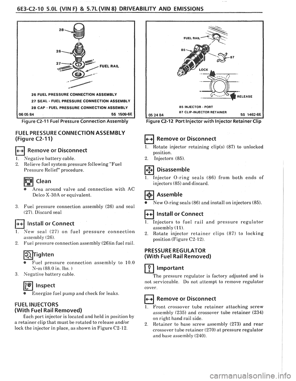
26 FUEL PRESSURE CONNECTION ASSEMBLY
27 DEAL - FUEL PRESSURE CONNECTION ASSEMBLY
28 CAP -FUEL PRESSURE CONNECTION ASSEMBLY
06 85 84 5S 1509-6E
Figure
C2-'11 Fuel Pressure Connection Assembly
FUEL PRESSURE CONNECTION ASSEMBLY
(Figure
CZ-'I I)
Remove or Disconnect
1. Negative battery cable.
2. Relieve fuel system pressure following "Fuel
Pressure Relief' procedure.
a Clean
@ Area around valve and connection with AC
Delco X-30A or equivalent.
3. Fuel pressure connection assembly (26) and seal
(27). Discard seal
Install or Connect
I. New seal (27) on fuel pressure connection
assembly
(26).
2. Fuel pressure connection assembly (26)in fuel rail.
- @ Fuel pressure connection assembly to 10.0
Norn (88.0 in. Ibs.
3. Negative battery cable.
inspect
@ Energize fuel pump and check for leaks.
FUEL INJECTORS
(With Fuel Wail Removed)
Each port injector is located and held in position by
a retainer clip that must be rotated to release
and/or
lock the injector in place, as shown in Figure (22-12.
FUEL RAIL
I 85 INJECTOR - PORT I
Figure CZ-12 Port Injector with Injector Retainer Clip
a Remove or Disconnect
1. Rotate injector retaining clip(s) (87) to unlocked
position.
2. Injectors (85).
+$ Disassemble
1. Injector O-ring seals (86) from both ends of
injectors
(85) and discard.
Assemble
@ New O-ring seals (86) and install on injectors (85).
Install or Connect
1. Injectors
to fuel rail and pressure regulator
assembly
(1 1).
2. Rotate
injector retainer clips (87) to loclring
position (Figure C2-12).
PRESSURE REGULATOR
(With Fuel Rail Removed)
Important
The pressure regulator is factory adjusted and is
not serviceable. Do not attempt to remove regulator
cover.
Remove or Disconnect
1. Front crossover tube retainer attaching screw
assembly
(235) and crossover tube retainer (234)
on right hand rail side.
2. Retainer to base screw assembly (273)
and rear
crossover tube retainer
(270) at pressure regulator
and base assembly (240).