manual transmission PONTIAC FIERO 1988 Service Repair Manual
[x] Cancel search | Manufacturer: PONTIAC, Model Year: 1988, Model line: FIERO, Model: PONTIAC FIERO 1988Pages: 1825, PDF Size: 99.44 MB
Page 2 of 1825
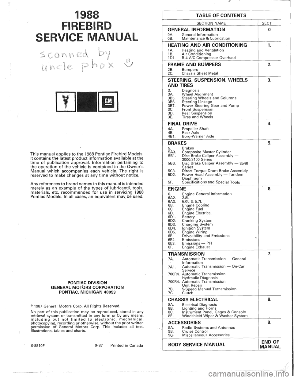
1988
SER
This manual applies to the 1988 Pontiac Firebird Models.
It contains the latest product information available at the
time of publication approval. lnformation pertaining to
the operation of the vehicle is contained in the Owner's
Manual which accompanies each vehicle. The right is
reserved to make changes at any time without notice.
Any references to brand names in this manual is intended
merely as an example of the types of
lubricant% tools,
materials, etc, recommended for use in servicing 1988
Pontiac Models. In all cases, an equivalent may be used.
PONTIAC DIVISION
GENERAL
MOTORS CORPORATION
PONTIAC, MICHIGAN 48053
1987 General Motors Corp. All Rights Reserved.
No part of this publication may be reproduced, stored in any
retrieval system or transmitted in any form or by any means,
including but not limited to electronic, mechanical,
photocopying, recording or otherwise, without the prior written
permission of General Motors Corp. This includes all text,
illustrations, tables and charts.
S-881 OF 9-87 Printed in Canada
TABLE OF CONTENTS
SECTION NAME
GENERAL INFORMATION
OA. General lnformation
OB. Maintenance & Lubrication
1 SECT.
HEATING AND AIR CONDITIONING
1A. Heating and Ventilation
1 B. Air Conditioning
1D1. R-4 AIC Com~ressor Overhaul
FRAME AND BUMPERS
2B. Bumpers 2C. Chassis Sheet Metal
STEERING, SUSPENSION, WHEELS
AND TIRES
3. Diagnosis
3A. Wheel Alignment
3B5. Steering Wheels and Columns 3B6. Steering Linkage 3B7. Power Steering Gear and Pump
3C. Front Suspension
3D. Rear Suspension
3E. Tires and Wheels
FINAL DRIVE
4A. Propeller Shaft
4B. Rear Axle
4B1. Bora-Warner Axle
BRAKES 5. Brakes 5A3. Comoosite Master Cvlinder 5B1. Disc r rake Caliper ~ssembly - 300013100 Series 5B6. Disc Brake Caliper Assembly - 3548
Series
5C3. Direct Torque Drum Brake Assembly 5D2. Power Head Assembly - Tandem Diaohraam 5F. ~~ecifications and Special Tools
ENGINE 6. Engine General lnformation 6A2. 2.8L 6A3. 5.OL & 5.7L 6B. Engine Cooling
6C. En~ine Fuel
6D. ~ngine Electrical 6D1. Battery 6D2. Cranking System 6D3. Charging System 6D4. Ignition System 6D5. Engine Wiring
6E. Driveabilitv and Emissions
6E2. ~missions' 6E3. Emissions - PFI
6F. Engine Exhaust
TRANSMISSION 7A. Automatic Transmission - General
lnformation
7A1. Automatic Transmission - On-Car
Service
700R4. Automatic Transmission Hydraulic Diagnosis
700R4. Automatic Transmission Unit Repair
76. 5-Speed Manual Transmission
7C. Clutch
CHASSIS ELECTRICAL 8A. Electrical Diagnosis
8B. Lighting and Horns
8C. Instrument
Panel, Gages
& Console
8E. Windshield Wiper &Washer System
ACCESSORIES 9A. Radio Systems and Antennas 9B. Cruise Control 9G. Miscellaneous Accessories
I BODY SERVICE MANUAL END
OF
MANUAL
Page 16 of 1825
- -
GENERAL INFORMATION OA-13
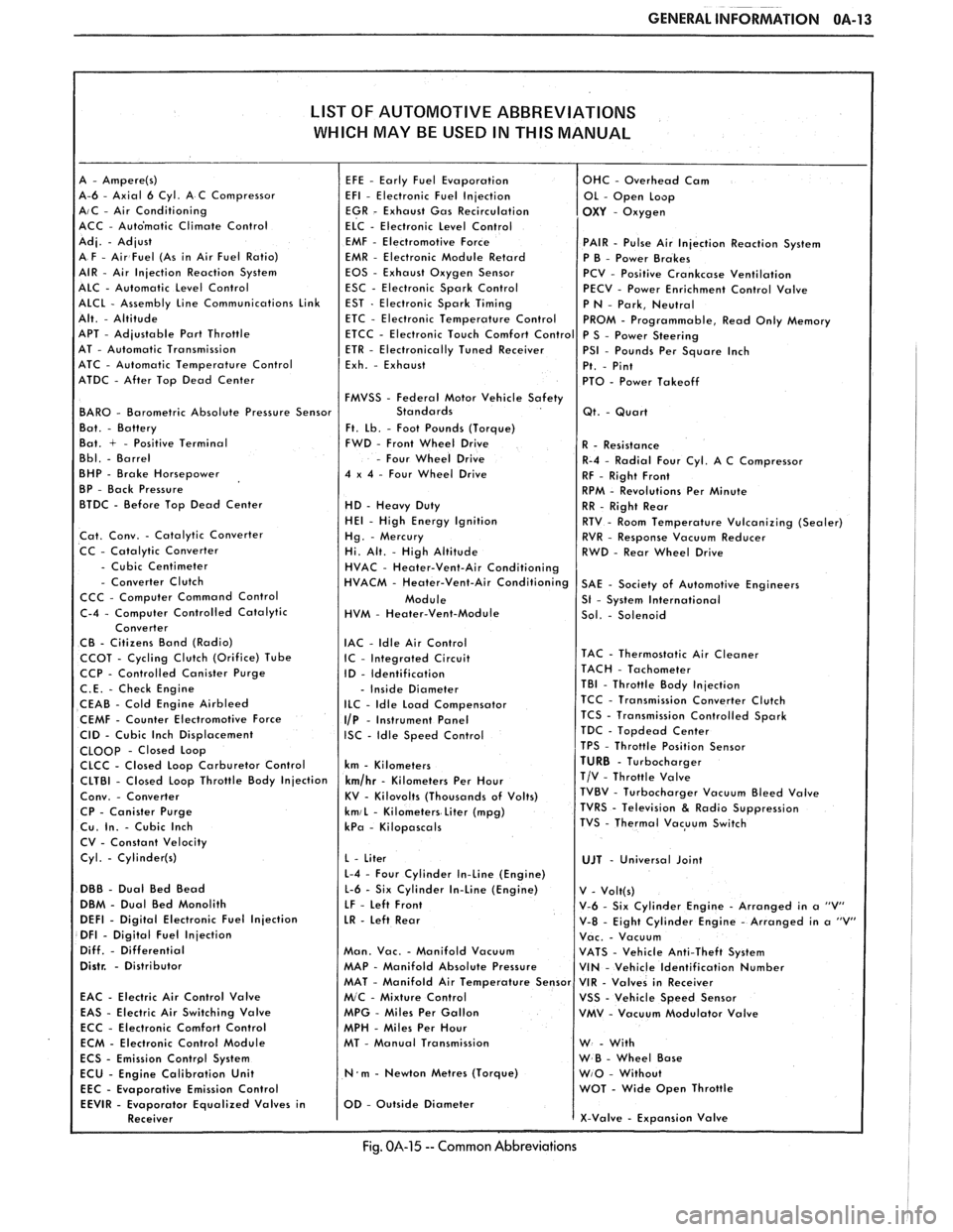
LIST OF AUTOMOTIVE ABBREVIATIONS
WHICH MAY
BE USED IN THIS MANUAL
A-6 - Axial 6 Cyl. A C Compressor AIC - Air Conditioning
ACC - Auto'matic Climate Control
EMF
- Electromotive Force PAIR - Pulse Air Injection Reaction System
EMR - Electronic Module Retard
P B - Power Brakes
EOS - Exhaust Oxygen Sensor
PCV - Positive Crankcase Ventilation
ESC - Electronic Spark Control
PECV - Power Enrichment Control Valve
APT
- Adjustable Part Throttle
AT - Automatic Transmission
ATC - Automatic Temperature Control
ATDC
- After Top Dead Center
FMVSS
- Federal Motor Vehicle Safety BAR0 - Barometric Absolute Pressure Sensor
Ft. Lb. - Foot Pounds (Torque)
Bat. + - Positive Terminal FWD - Front Wheel Drive
- Four Wheel Drive
BHP - Brake Horsepower 4 x 4 - Four Wheel Drive
BP - Back Pressure
BTDC - Before Top Dead Center
HD - Heavy Duty HE1 - High Energy Ignition
Cat. Conv. - Catalytic Converter
CC - Catalytic Converter
- Cubic Centimeter - Converter Clutch
CCC - Computer Command Control
HVM
- Heater-Vent-Module
IAC
- ldle Air Control CCOT - Cycling Clutch (Orifice) Tube IC - Integrated Circuit CCP - Controlled Canister Purge
ID - Identification
C.E. - Check Engine - Inside Diameter
CEAB - Cold Engine Airbleed ILC - Idle Load Compensator
CEMF - Counter Electromotive Force I/P - Instrument Panel
CID - Cubic Inch Displacement ISC - Idle Speed Control CLOOp - Closed Loop
CLCC - Closed Loop Carburetor Control km - Kilometers
CP
- Canister Purge kmiL - Kilometers Liter (mpg) Cu. In. - Cubic Inch kPa - Kilopascals
CV - Constant Velocity
Cyl.
- Cylinder(s)
L-4 - Four Cylinder In-Line (Engine)
DBB - Dual Bed Bead L-6 - Six Cylinder In-Line (Engine)
DBM - Dual Bed Monolith
LF - Left Front DEFl - Digital Electronic Fuel Injection LR - Left Rear DFI - Digital Fuel Injection
Diff. - Differential Man. Vac. - Manifold Vacuum Distr. - Distributor MAP - Manifold Absolute Pressure
EAC
- Electric Air Control Valve
EAS - Electric Air Switching Valve MPG - Miles Per Gallon
ECC - Electronic Comfort Control
MPH - Miles Per Hour
ECM - Electronic Control Module MT - Manual Transmission
N.m - Newton Metres (Torque)
Emission Control
Fig. 014-15 -- Common Abbreviations
Page 18 of 1825
MAINTENANCE AND LUBRICATION OB-1
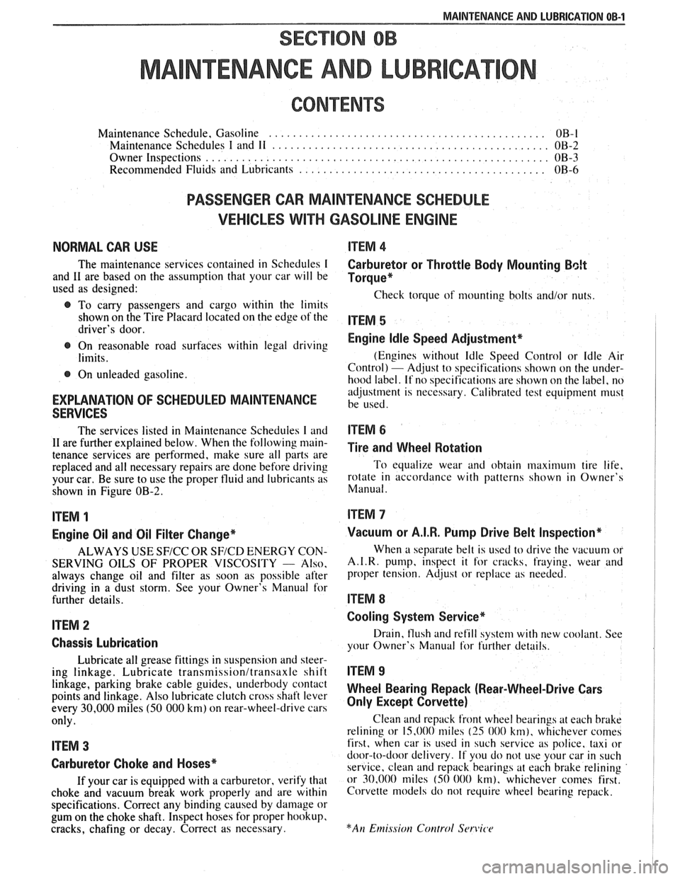
SECTION OB
NTENANCE AND LUBR
CONTENTS
Maintenance Schedule, Gasoline .............................................. OB-l
Maintenance Schedules I and 11 .............................................. OB-2
Owner Inspections
......................................................... OB-3
Recommended Fluids and Lubricants ......................................... OB-6
PASSENGER CAR MAINTENANCE SCHEDULE
VEHICLES
WITH GASOLINE ENGINE
NORMAL CAR USE ITEM 4
The maintenance services contained in Schedules I Carburetor or Throttle Body Mounting Bolt
and 11 are based on the assumption that your car will be Torque* used as designed:
Check torque of mounting bolts and/or nuts. @ To carry passengers and cargo within the limits
shown on the Tire Placard located on the edge of the ITEM 5 driver's door.
@ On reasonable road surfaces within legal driving Engine Idle Speed Adjustment*
limits. (Engines
without Idle Speed Control or Idle Air
Control) - Adjust to specifications shown on the under- @ On unleaded gasoline.
hood label. If no specifications are shown on the label, no
adjustment is necessary. Calibrated test equipment must
EXPLANATION OF SCHEDULED MAINTENANCE be used. SERVICES
The services listed in Maintenance Scheduies I and ITEM 6
11 are further explained below. When the following main- ~i~~ and wheel aotation tenance services are performed, make sure all parts are
replaced and all necessary repairs are done before driving To equalize wear and obtain maximum tire life,
your car. Be sure to use the proper fluid and lubricants as rotate in accordance with patterns shown in Owner's
shown in Figure OB-2. Manual.
ITEM 1
Engine Oil and Oil Filter Change*
ALWAYS USE SFICC OR SF/CD ENERGY CON-
SERVING OILS OF PROPER VISCOSITY
- Also.
always change oil and filter as soon as possible after
driving in a dust storm. See your Owner's Manual for
further details.
ITEM 2
Chassis Lubrication
Lubricate all grease fittings in suspension and steer-
ing linkage. Lubricate
transmissionltransaxle shift
linkage, parking brake cable guides, underbody contact
points and linkage. Also lubricate clutch cross shaft lever
every
30,000 miles (50 000 km) on rear-wheel-drive cars
only.
ITEM 3
Carburetor Choke and Hoses*
If your car is equipped with a carburetor, verify that
choke and vacuum break work properly and are within
specifications. Correct any binding caused by damage or
gum on the choke shaft. Inspect hoses for proper hookup,
cracks, chafing or decay. Correct as necessary.
Vacuum or A.I.R. Pump Drive Belt Inspection*
When a separate belt is used to drive the vacuum or
A.I.R.
pump, inspect it for cracks, fraying, wear and
proper tension. Adjust or replace as needed.
ITEM 8
Cooling System Service*
Drain, flush and refill system with new coolant. See
your Owner's Manual
for further details.
ITEM 9
Wheel Bearing Repack (Rear-Wheel-Drive Cars
Only Except Corvette)
Clean and repack front wheel bearings at each brake
relining or 15,000 miles
(25 000 km), whichever comes
first, when car is used in such service as police, taxi or
door-to-door delivery. If you do not use your car in such
service, clean and repack bearings at each brake relining
or 30,000 miles
(50 000 km), whichever comes first.
Corvette models do not require wheel bearing repack.
Page 20 of 1825
F CARLINE
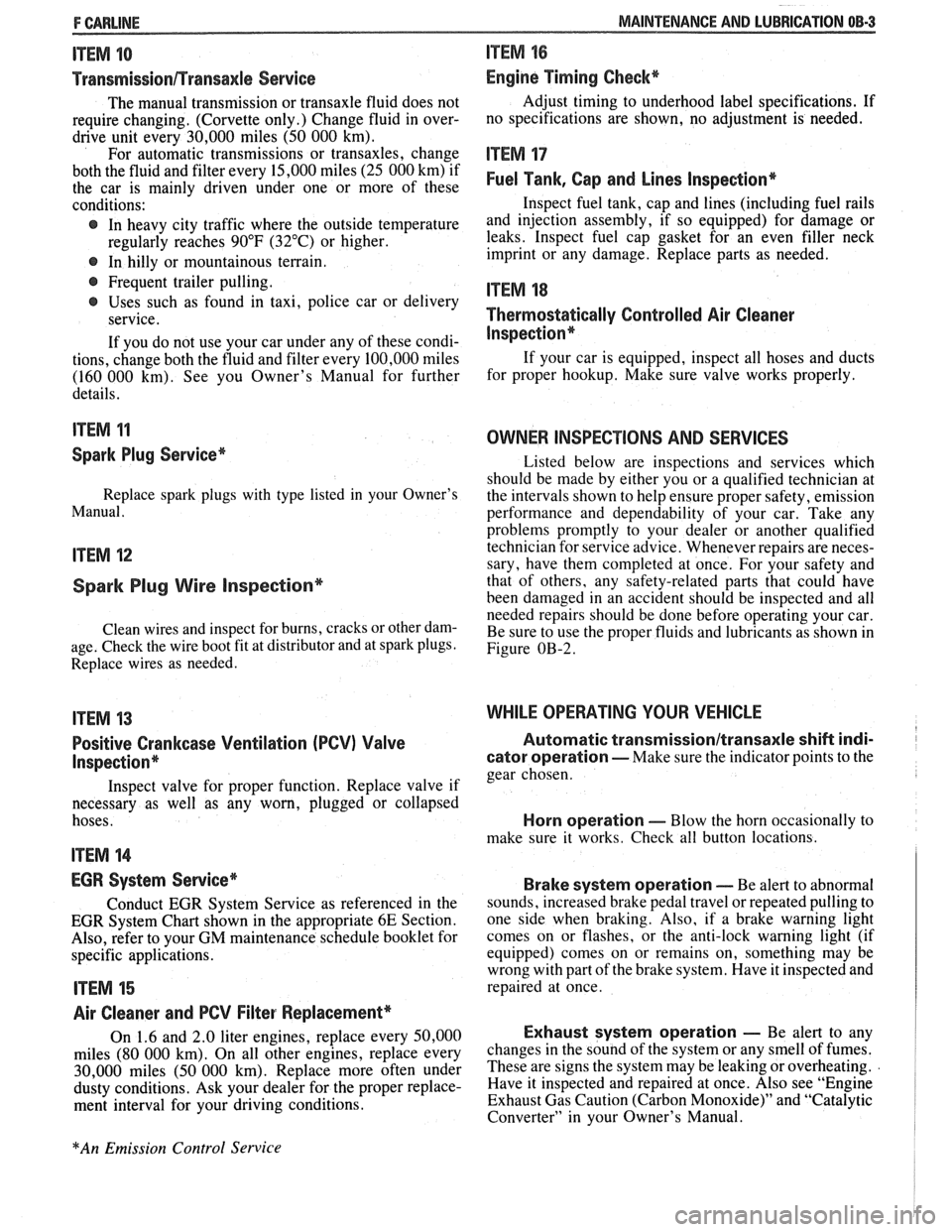
ITEM 10
TransmissionRransaxle Service
The manual transmission or transaxle fluid does not
require changing. (Corvette only.) Change fluid in over-
drive unit every 30,000 miles (50 000 km).
For automatic transmissions or transaxles, change
both the fluid and filter every 15,000 miles (25 000 km) if
the car is mainly driven under one or more of these
conditions:
@ In heavy city traffic where the outside temperature
regularly reaches 90°F (32°C) or higher.
@ In hilly or mountainous terrain.
@ Frequent trailer pulling.
@ Uses such as found in taxi, police car or delivery
service.
If you do not use your car under any of these condi-
tions, change both the fluid and filter every 100,000 miles
(160 000 km). See you Owner's Manual for further
details.
ITEM 11
Spark Plug Service*
Replace spark plugs with type listed in your Owner's
Manual.
ITEM 12
Spark Plug Wire Inspection*
Clean wires and inspect for burns, cracks or other dam-
age. Check the wire boot fit at distributor and at spark plugs.
Replace wires as needed.
ITEM 13
Positive Crankcase Ventilation (PCV) Valve
Inspection*
Inspect valve for proper function. Replace valve if
necessary as well as any worn, plugged or collapsed
hoses.
ITEM 14
EGR System Service*
Conduct EGR System Service as referenced in the
EGR System Chart shown in the appropriate 6E Section.
Also, refer to your GM maintenance schedule booklet for
specific applications.
ITEM 15
Air Cleaner and PCV Filter Replacement*
On 1.6 and 2.0 liter engines, replace every 50,000
miles (80 000 km). On all other engines, replace every
30,000 miles (50 000 km). Replace more often under
dusty conditions. Ask your dealer for the proper replace-
ment interval for your driving conditions.
MAINTENANCE AND LUBRICATION 08-3
ITEM 16
Engine Timing Check*
Adjust timing to underhood label specifications. If
no specifications are shown, no adjustment is needed.
ITEM 17
Fuel Tank, Cap and Lines Inspection*
Inspect fuel tank, cap and lines (including fuel rails
and injection assembly, if so equipped) for damage or
leaks. Inspect fuel cap gasket for an even filler neck
imprint or any damage. Replace parts as needed.
ITEM 18
Thermostatically Controlled Air Cleaner
Inspection*
If your car is equipped, inspect all hoses and ducts
for proper hookup. Make sure valve works properly.
OWNER INSPECTIONS AND SERVICES
Listed below are inspections and services which
should be made by either you or a qualified technician at
the intervals shown to help ensure proper safety, emission
performance and dependability of your car. Take any
problems promptly to your dealer or another qualified
technician for service advice. Whenever repairs are neces-
sary, have them completed at once. For your safety and
that of others, any safety-related parts that could have
been damaged in an accident should be inspected and all
needed repairs should be done before operating your car.
Be sure to use the proper fluids and lubricants as shown in
Figure OB-2.
WHILE OPERATING YOUR VEHICLE
Automatic transmissionltransaxle shift indi-
cator operation - Make sure the indicator points to the
gear chosen.
Horn operation - Blow the horn occasionally to
make sure it works. Check all button locations.
I
Brake system operation -- Be alert to abnormal
sounds, increased brake pedal travel or repeated pulling to
one side when braking. Also, if a brake warning light
comes on or flashes, or the anti-lock warning light (if
equipped) comes on or remains on, something may be
wrong with part of the brake system. Have it inspected and
repaired at once.
Exhaust system operation - Be alert to any
changes in the sound of the system or any smell of fumes.
These are signs the system may be leaking or overheating.
.
Have it inspected and repaired at once. Also see "Engine
Exhaust Gas Caution (Carbon Monoxide)" and "Catalytic
Converter" in your Owner's Manual.
*An Emission Control Service
Page 21 of 1825
OB-4 MAINTENANCE AND LUBRICATION
Tire and wheel operation - Be alert to a vibra-
tion of the steering wheel or seat at normal highway
speeds. This may mean a wheel balance is needed. Also, a
pull right or left on a straight, level road may show the
need for
a tire pressure adjustment or wheel alignment.
Steering system operation - Be alert to
changes in steering action. An inspection is needed when
the steering wheel is harder to turn or has too much free
play or if unusual sounds are noted when turning or
parking.
Headlight aim operation - Take note of light
pattern occasionally. If beam aim doesn't look right,
headlights should be adjusted.
AT EACH FUEL FILL
Engine oil level check - Check engine oil level
and add if necessary. See your Owner's
Manual for further
details.
NOTICE: A large loss in this system may indicate a
problem. Have it inspected and repaired at once.
Engine coolant level and condition - Check
engine coolant level in coolant reservoir tank and add if
necessary. Replace if dirty or rusty. See your Owner's
Manual for further details.
NOTICE: A large loss in this system may indicate a
problem. Have it inspected and repaired at once.
Windshield washer fluid level check -- Check
washer fluid level in container and add if necessary.
Hood latch operation - When opening hood on
cars equipped with hoods that open from the front, note
the operation of secondary latch. It should keep hood from
opening all the way when primary latch is released. Make
sure that hood closes firmly.
AT LEAST MONTI-ILY
Tire and wheel inspection and pressure
check--
Check tires for abnormal wear or damage. Also,
check for damaged wheels. Keep pressures as shown on
Tire Placard on the driver's door (include spare unless it is
a stowaway). Pressure should b\: checked when tires are
"cold". See "Tires" in Owner's Manual for further
infomation.
Light operation check - Check operation of
license plate light, side-marker lights, headlights includ-
ing high beams, parking lights, taillights, brake lights.
turn signals, backup lights, instrument panel and interior
lights and hazard warning flashers.
Fluid leak check - After the car has been parked
for a while, inspect the surface beneath the car for water,
oil, fuel or other fluids. Water dripping from the air
conditioning system after use is normal. If you notice fuel
leaks or fumes, the cause should be found and corrected at
once.
AT LEAST TWICE A YEAR (FOR EXAMPLE,
EVERY SPRING AND FALL)
Power steering pump fluid level check --
Check power steering pump fluid level in accordance with
Owner's Manual instructions and keep at proper level.
NOTICE: A large loss in this system may indicate a
problem. Have it inspected and repaired at once.
Brake master cylinder reservoir fluid level
check ---- Check fluid and keep at proper level. Note: It is
normal for the brake fluid level to go down slightly as the
brake pads wear
- so be sure to keep reservoir filled.
NOTICE: A large loss in this system may indicate a
problem. Have
it inspected and repaired at once.
Clutch system service --- manual transmis-
sionltransaxle --- For cars equipped with hydraulic
clutch system, check the reservoir fluid level and add fluid
as required. All others, check clutch pedal free travel and
adjust as necessary. See your Owner's Manual for further
details.
~
NOTICE: A large loss in this system may indicate a
problem. Have it inspected and repaired at once.
Weatherstrip Lubrication - Clean surface and
then apply a thin film of silicone grease with a clean cloth.
EACH TIME OIL IS CHANGED
Automatic and manual transmissionltrans-
axle fluid level check - Check transmission/transaxle
fluid level and add as required. (Corvette only) if equipped
with manual transmission
- check fluid in the overdrive
unit and add as required.
NOTICE: A large loss in this system may indicate a
problem. Have
it inspected and repaired at once.
Brake systems inspection - For convenience,
the following should be done when wheels are removed
for rotation: Inspect lines and hoses for proper hookup,
binding, leaks, cracks, chafing, etc. Inspect disc brake
pads for wear and rotors for surface condition. Also in-
spect drum brake linings for wear and cracks. Inspect
other brake parts, including drums, wheel cylinders, park-
ing brake, etc. at the same time. Check parking brake
adjustment.
INSPECT BRAKES MORE OFTEN IF DRIVING
HABITS OR CONDITIONS RESULT IN FREQUENT
BRAKING.
Steering, suspension and front drive axle
boot and seal inspection
- Inspect front and rear
suspension and steering system for damaged, loose or
missing parts, signs of wear or lack of lubrication. Inspect
power steering lines and hoses for proper hookup, bind-
ing, leaks, cracks, chafing, etc. (On cars equipped with
manual steering gear, check for seal leakage.) On
front-
wheel-drive cars, clean then inspect drive axle boot seals
for damage, tears or leakage. Replace seals if necessary.
Exhaust system inspection - Inspect complete
system. Inspect body near the exhaust system. Look for
broken, damaged, missing or out-of-position parts as well
as open seams, holes, loose connections or other condi-
tions which could cause a heat buildup in the tloor pan or
could let exhaust fumes seep into the trunk or passenger
compartment.
Page 22 of 1825
MAINTENANCE AND LUBRICATION OB-5
Throttle linkage inspection -- Inspect for inter-
ference, binding, damaged or missing parts.
Engine drive belts inspection - Inspect all
belts for cracks, fraying and wear. Adjust or replace as
needed.
Rear axle service (if equipped) - Check gear
lubricant level and add if needed. For cars equipped with a
limited slip rear axle, fluid does not require changing
(except Caprice and Corvette
- change fluid and required
additive at first
7,500 miles (12 500 km). See your
Owner's Manual or "Recommended Fluids
& Lubricants
Chart" in this section.
IF YOU USE YOUR GAR TO PULL A TRAILER,
CHANGE GEAR LUBRICANT EVERY 7,500 MILES
(12 500 KM).
NOTICE: A large loss in this system may indicate a
problem. Have it inspected and repaired at once.
Power antenna - Clean and then lubricate power
antenna mast. The proper lubricant as shown in Figure
OB-2 should be used.
AT LEAST ONCE A YEAR
Lap and shoulder belts condition and opera-
tion
- Inspect belt system, including webbing, buckles,
latch plates, retractors, guide loops and anchors.
Moveable head restraint operation - On cars
with moveable restraints, make sure restraints stay in the
desired position. (See adjustment instructions in your
Owner's Manual.)
Seatback latch and recliner operation on
cars equipped
with recliner seat --- Be sure seat-
backs latch on those cars with folding seats using mechan-
ical latches. Make sure the recliner is holding by pushing
and pulling on the top of the
seatback while it is reclined.
See your Owner's Manual for seat operating information.
Spare tire and jack storage- Be alert to rattles
in rear of car. Make sure the space tire, all jacking equip-
ment, any tire inflator and any covers or doors are securely
stowed at all times. Oil jack ratchet or screw mechanism
after each use.
Key lock service - Lubricate key lock cylinder at
least annually.
Body lubrication service - Lubricate all body
door hinges including the tailgate or hatchback lid (if
equipped). Also lubricate the body hood, fuel door and
rear compartment hinges and latches including interior
glove box and counsel doors, and any folding seat
hardware.
"Fansmissionltransaxle neutral or clutch
starl switch operation
CAUnON: Before pedorming the follow-
ing safety switch check, be sure to have
enough room around the car. Then, firmly
apply both the parking brake (see your
Owner's Manual for procedure) and the
regular brakes. Do not use the accelerator pedal.
If the engine
starls, be ready to turn
off the ignition promptly. Take these pre-
cautions because the car could move
without warning and possibly cause per-
sonal injury or properly damage. On auto-
matic transmissionltransaxle cars, try to
starl the engine in each gear. The starler
should crank only in "Park" or "Neutral."
On manual transmissionltransaxle cars,
place the
shiR lever in "Neutral," push the
clutch halfway and try to starl. The starler
should crank only when the clutch is fully
depressed.
Steering column lock operation
- While
parked, try to turn key to "Lock" in each gear range. The
key should turn to "Lock" only when gear is in "Park" on
automatic or "Reverse" on manual
transmissionltransax-
le. On cars with key release lever, try to turn key toULock"
without depressing the lever. The key should turn to
"Lock" only with the key lever depressed. On all vehicles,
the key should come out only in "Lock."
Parking brake and transmissionltransaxle
"Park" mechanism operation
CAUT1ON:Before checking the holding
ability of the parking brake and automatic
transmissionltransaxle "Park" mecha-
nism, park on a fairly steep hill with
enough room for movement in the down-
hill direction. To reduce the risk of person-
al injury or property damage, be prepared
to apply the regular brakes promptly if the
car begins to move.
To check the parking brake, with the engine running and
transmission/transaxle in "Neutral." slowly remove foot
pressure from the regular brake pedal (until the car is held
by only the parking brake).
To check the automatic transmissionltransaxle "Park"
mechanism holding ability, release all brakes after shift-
ing the transmissionltransaxle to "Park."
ljnderbody flushing - At least every spring,
tlush from the underbody with plain water any corrosive
materials used for ice and snow removal and dust control.
Take care to thoroughly clean any areas where mud and
other debris can collect.
Sediment packed in closed areas
of the vehicle should be loosened before being flushed.
Engine cooling system service - Inspect
coolant and freeze protection. If dirty or rusty, drain, flush
and refill with new coolant. Keep coolant
at the proper
mixture as specified in your Owner's Manual. This pro-
vides proper freeze protection. corrosion inhibitor level
and engine operating temperature. Inspect hoses and re-
place if cracked. swollen or deteriorated. Tighten hose
clamps. Clean outside of radiator and air conditioning
condensor. Wash radiator filler cap and neck.
To help
ensure proper operation. a pressure test of both the cooling
system and cap is also recommended. (See maintenance
schedule charts in Figure
OB-l for the recommended
coolant change interval.)
Page 228 of 1825
REAR SUSPENSION 3D-7
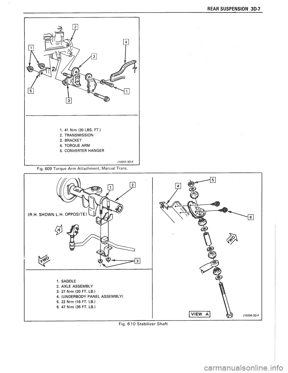
1. 41 N-rn (30 LBS. FT.)
2. TRANSMISSION
3. BRACKET
4. TORQUE ARM
5. CONVERTER HANGER
Fig. 609 Torque Arm Attachment, Manual Trans.
Page 239 of 1825
3E-8 TIRES AND WHEELS
nearest the valve stem, and a 1/2 ounce balance weight
should be added 180" opposite the locking nut on the
wheel's inboard side.
When rotating tires, always re-install the locking
nut nearest the tire valve stem so that it remains
opposite the 1/2 ounce balance weight. This procedure
will improve the on-car wheel balance by compensating
for the heavy locking wheel nut.
Off-Car Balancing
Most electronic off-car balancers are more
accurate than the on-car spin balancers. They are easy
to use and give a dynamic (two plane) balance.
Although they do not correct for drum or rotor
unbalance as does on-car spin balancing, this is
overcome by their accuracy (usually to within 1/8
ounce). When balancing off-car, the wheel should
locate on the balancer with a cone through the back
side of the center pilot hole (not by the wheel stud
holes).
On-Car Balancing
When needed, on-car balancing will help correct
vibrations due to brake drum, rotor, and wheel cover
imbalance.
When balancing on car, do not remove the
balance weights from the off-car dynamic balance. If
more than one ounce of additional weight is required,
it should be split between the inner and outer rim
flange.
NOTICE: The driven tire and wheel assemblies
should be spun using the engine. Limit speed as
stated in the following Caution.
CAUTION: Do not spin the drive
wheels faster than
35 mph (55 km/h)
as indicated by the speedometer. This
limit is necessary because the
speedometer indicates only one-half
of the actual wheel speed when one
drive wheel is spinning and the other
drive wheel is stopped. Personal injury
and damage may result from high
speed spinning.
CAUTION: On cars equipped with
limited slip rear axles, do not attempt
to balance a tire on a
drive wheel with
the other drive wheel on the ground.
The car may drive through this wheel
and cause the car to move
unexpectedly, resulting in personal
injury and property damage.
To distinguish between standard rear axle and
limited slip, raise rear of car so both tires are clear of
ground. With the transmission in park (in gear with
manual transmission), attempt to turn one wheel by
hand. If the wheel can be turned, it is a standard rear
axle; if the wheel cannot be turned, it is a limited slip
rear axle. Also, check for Limited Slip
(G80) on Service
Parts Identification label.
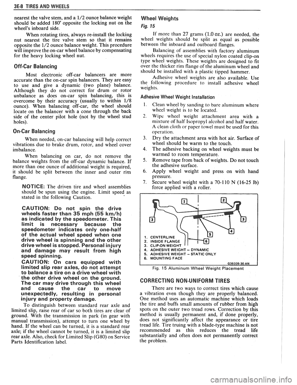
Wheel Weights
Fig. 15
If more than 27 grams (1.0 oz.) are needed, the
wheel weights should be split as equal as possible
between the inboard and outboard flanges.
Balancing of' assemblies with factory aluminum
wheels requires the use of special nylon coated clip-on
type wheel weights. These weights are designed to fit
over the thicker rim flange of the aluminum wheel and
should be installed with a plastic tipped hammer.
Adhesive wheel weights are also available. Use
the following procedure to install adhesive wheel
weights.
Adhesive Wheel Weight Installation
1. Clean wheel by sanding to bare aluminum where
wheel weight is to be located.
2. Wipe wheel weight attachment area with a
mixture of half Isopropyl alcohol and half water.
A clean cloth or paper towel niust be used for this
operat ion.
3. Dry the attachment area with hot air. Surface of
wheel should be warm to the touch.
4. The adhesive backing on wheel weights must be
warmed to room temperature.
5. Remove tape from back of weights. Do not touch
the adhesive surface.
6. Apply wheel weight and press on with hand
pressure.
7. Secure wheel weight with a 70-1 10
N (16-25 lb)
force applied with a roller.
CENTERLINE
1 INSIDE FLANGE CLIPBN WEIGHT 4. ADHESIVE WEIGHT - DYNAMIC 5. ADHESIVE WEIGHT -STATIC ONLY 6. MOUNTING FACE
Fig. 15 Aluminum Wheel Weight Placement
CORRECTING NON-UNIFORM TIRES
There are two ways to correct tires which cause
a vibration even though they are properly balanced.
One method uses an automatic machine which loads
the tire and buffs small amounts of rubber from high
spots on the outer two tread rows. Correction by this
method is usually permanent and, if done properly,
does not significantly affect the appearance or tire
tread life. Tire truing with a blade-type
machine is not
recommended as this reduces the tread life
substantially and often does not permanently correct
the problem.
Page 250 of 1825
PROPELLER SHAFT 4A-9
damage, do not place any tool betvveen pro-
peller shaft yoke and the universal joint
spider.
When making the rear propeller shaft connection,
be sure to align marks made on the pinion flange and
propeller shaft prior to removal.
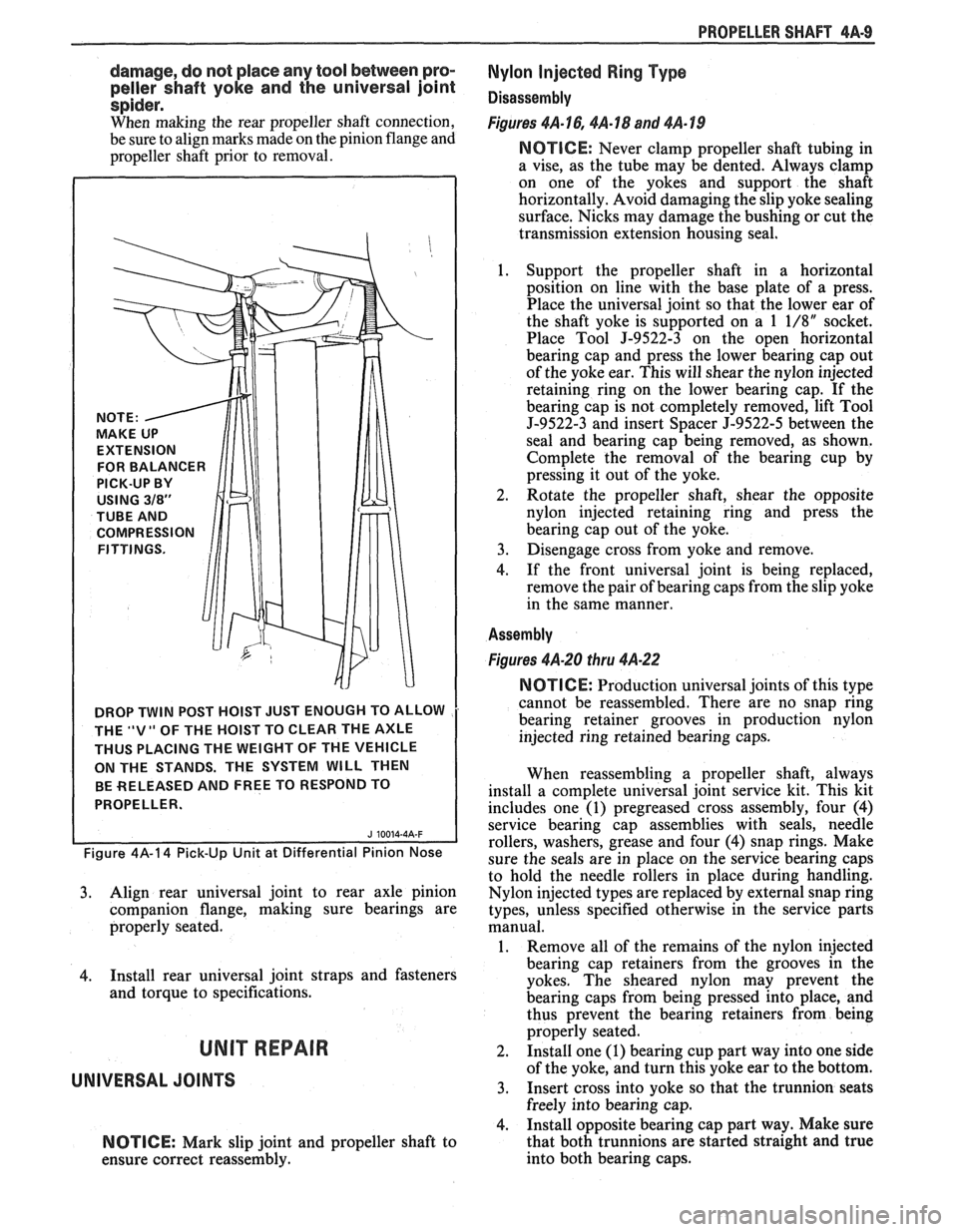
DROP TWIN POST HOIST JUST ENOUGH TO ALLOW
THE
"V" OF THE HOIST TO CLEAR THE AXLE
THUS PLACING THE WEIGHT OF THE VEHICLE
ON THE STANDS. THE SYSTEM
WILL THEN
BE RELEASED AND FREE TO RESPOND TO
PROPELLER.
Figure 4A-14 Pick-Up Unit at Differential Pinion Nose
3. Align rear universal joint to rear axle pinion
companion flange, making sure bearings are
properly seated.
4. Install rear universal joint straps and fasteners
and torque to specifications.
UNIT REPAIR
UNIVERSAL JOINTS
NOTICE: Mark slip joint and propeller shaft to
ensure correct reassembly.
Nylon Injected Ring Type
Disassembly
Figures 4A-16,4A-18 and 4A-19
NOTICE: Never clamp propeller shaft tubing in
a vise, as the tube may be dented. Always clamp
on one of the yokes and support the shaft
horizontally. Avoid damaging the slip yoke sealing
surface. Nicks may damage the bushing or cut the
transmission extension housing seal.
1. Support the propeller shaft in a horizontal
position on line with the base plate of a press.
Place the universal joint so that the lower ear of
the shaft yoke is supported on a
1 1/8" socket.
Place Tool
J-9522-3 on the open horizontal
bearing cap and press the lower bearing cap out
of the yoke ear. This will shear the nylon injected
retaining ring on the lower bearing cap. If the
bearing cap is not completely removed, lift Tool
5-9522-3 and insert Spacer J-9522-5 between the
seal and bearing cap being removed, as shown.
Complete the removal of the bearing cup by
pressing it out of the yoke.
2. Rotate
the propeller shaft, shear the opposite
nylon injected retaining ring and press the
bearing cap out of the yoke.
3. Disengage cross from yoke and remove.
4. If the front universal joint is being replaced,
remove the pair of bearing caps from the slip yoke
in the same manner.
Assembly
Figures 4A-20 thru 4A-22
NOTICE: Production universal joints of this type
cannot be reassembled. There are no snap ring
bearing retainer grooves in production nylon
injected ring retained bearing caps.
When reassembling a propeller shaft, always
install a complete universal joint service kit. This kit
includes one
(1) pregreased cross assembly, four (4)
service bearing cap assemblies with seals, needle
rollers, washers, grease and four
(4) snap rings. Make
sure the seals are in place on the service bearing caps
to hold the needle rollers in place during handling.
Nylon injected types are replaced by external snap ring
types, unless specified otherwise in the service parts
manual.
1. Remove all of the remains of the nylon injected
bearing cap retainers from the grooves in the
yokes. The sheared nylon may prevent the
bearing caps from being pressed into place, and
thus prevent the bearing retainers from being
properly seated.
2. Install one (1) bearing cup part way into one side
of the yoke, and turn this yoke ear to the bottom.
3. Insert cross into yoke so that the trunnion seats
freely into bearing cap.
4. Install opposite bearing cap part way. Make sure
that both trunnions are started straight and true
into both bearing caps.
Page 359 of 1825
6A2-8 2.8 LITER V-6
6. Install new mount.
7. Lower transmission.
8. Torque nuts to specifications.
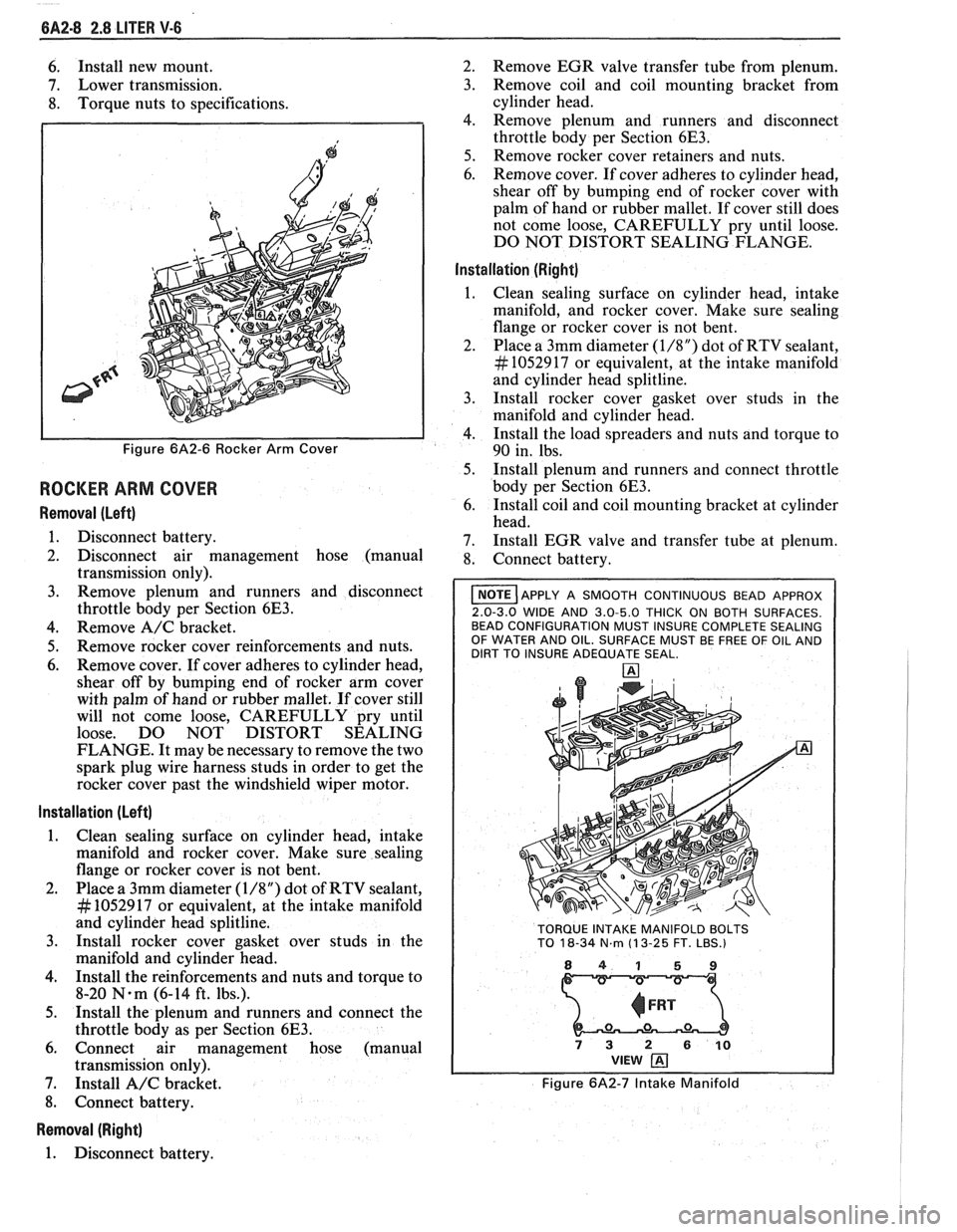
Figure 6A2-6 Rocker Arm Cover
ROCKER ARM COVER
Removal (Left)
1. Disconnect battery.
2. Disconnect air management hose (manual
transmission only).
3. Remove plenum and runners and disconnect
throttle body per Section
6E3.
4. Remove A/C bracket.
5. Remove rocker cover reinforcements and nuts.
6. Remove cover. If cover adheres to cylinder head,
shear off by bumping end of rocker arm cover
with palm of hand or rubber mallet. If cover still
will not come loose, CAREFULLY pry until
loose. DO NOT DISTORT SEALING
FLANGE. It may be necessary to remove the two
spark plug wire harness studs in order to get the
rocker cover past the windshield wiper motor.
Installation (Left)
1. Clean sealing surface on cylinder head, intake
manifold and rocker cover. Make sure sealing
flange or rocker cover is not bent.
2. Place a 3mm diameter
(1/8") dot of RTV sealant,
# 1052917 or equivalent, at the intake manifold
and cylinder head splitline.
3. Install rocker cover gasket over studs in the
manifold and cylinder head.
4. Install the reinforcements and nuts and torque to
8-20
N.m (6-14 ft. lbs.).
5. Install the plenum and runners and connect the
throttle body as per Section
6E3.
6. Connect air management hose (manual
transmission only).
7. Install
A/C bracket.
8. Connect battery.
Removal (Right)
1. Disconnect battery. 2.
Remove EGR valve transfer tube from plenum.
3. Remove coil and coil mounting bracket from
cylinder head.
4. Remove plenum and runners and disconnect
throttle body per Section
6E3.
5. Remove rocker cover retainers and nuts.
6. Remove cover. If cover adheres to cylinder head,
shear off by bumping end of rocker cover with
palm of hand or rubber mallet. If cover still does
not come loose, CAREFULLY pry until loose.
DO NOT DISTORT SEALING FLANGE.
Installation (Right)
Clean sealing surface on cylinder head, intake
manifold, and rocker cover. Make sure sealing
flange or rocker cover is not bent.
Place a 3mm diameter
(1/8") dot of RTV sealant,
# 1052917 or equivalent, at the intake manifold
and cylinder head splitline.
Install rocker cover gasket over studs in the
manifold and cylinder head.
Install the load spreaders and nuts and torque to
90 in. lbs.
Install plenum and runners and connect throttle
body per Section
6E3.
Install coil and coil mounting bracket at cylinder
head.
Install EGR valve and transfer tube at plenum.
Connect battery.
I NOTE ]APPLY A SMOOTH CONTINUOUS BEAD APPROX
2.0-3.0 WIDE AND 3.0-5.0 THICK ON BOTH SURFACES.
BEAD CONFIGURATION MUST INSURE COMPLETE SEALING
OF WATER AND OIL. SURFACE MUST BE FREE OF OIL AND
DIRT TO INSURE ADEQUATE SEAL.
TORQUE INTAKE MANIFOLD BOLTS
TO
18-34 N.m (1 3-25 FT. LBS.)
841 59
73 2 610 VIEW
Figure 6A2-7 Intake Manifold