fuel tank removal PONTIAC FIERO 1988 Service Repair Manual
[x] Cancel search | Manufacturer: PONTIAC, Model Year: 1988, Model line: FIERO, Model: PONTIAC FIERO 1988Pages: 1825, PDF Size: 99.44 MB
Page 346 of 1825
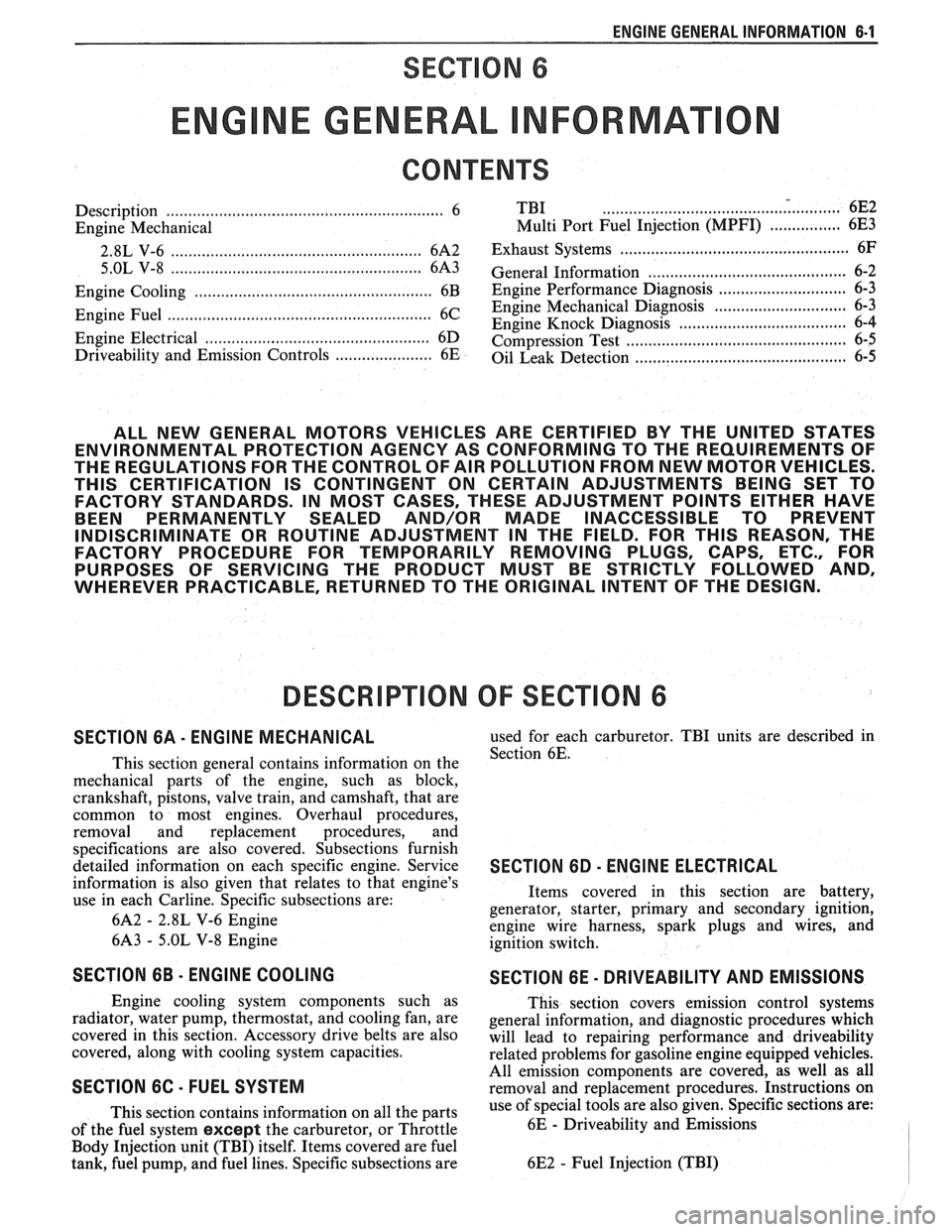
ENGINE GENERAL INFORMATION 6-1
SECTION 6
NE GENERAL NFORMAT
Description ............................................................... 6 TBI ...................................... .. ...... 6E2 ................ Engine Mechanical Multi Port Fuel Injection (MPFI) 6E3 -
............................................... 2.8L V-6 ....................................................... 6A2 Exhaust Systems 6F
5.OL V-8 ......................................................... 6A3 ~~~~~~l ~~f~~~~ti~~ ..................................... 6-2
............................ Engine Cooling ...................................................... 6B Engine Performance Diagnosis 6-3 ............................. Engine Fuel 6C Engine Mechanical Diagnosis
6-3 ........................................................... ................................... Engine Knock Diagnosis 6-4
Engine Electrical ................................................... 6D Compression Test ...................................... ... 6-5
................... Driveability and Emission Controls ...................... 6E Oil Leak Detection .. ..................... 6-5
ALL NEW GENERAL MOTORS VEHICLES ARE CERTIFIED BY THE UNITED STATES
ENVIRONMENTAL PROTECTION AGENCY AS CONFORMING TO THE REQUIREMENTS OF
THE REGULATIONS FOR THE CONTROL OF AIR POLLUTION FROM NEW MOTOR VEHICLES.
THlS CERTIFICATION IS CONTINGENT ON CERTAIN ADJUSTMENTS BEING SET TO
FACTORY STANDARDS. IN MOST CASES, THESE ADJUSTMENT POINTS EITHER HAVE
BEEN PERMANENTLY SEALED AND/OR MADE INACCESSIBLE TO PREVENT
INDISCRIMINATE OR ROUTINE ADJUSTMENT IN THE FIELD. FOR
THlS REASON, THE
FACTORY PROCEDURE FOR TEMPORARILY REMOVING PLUGS, CAPS, ETC., FOR
PURPOSES OF SERVICING THE PRODUCT MUST BE STRICTLY FOLLOWED AND,
WHEREVER PRACTICABLE, RETURNED TO THE ORIGINAL INTENT OF THE DESIGN.
DESCRIPTION OF: SECTION 6
SECTION 6A - ENGINE MECHANICAL used for each carburetor. TBI units are described in
This section general contains information on the Section 6E.
mechanical parts of the engine, such as block,
crankshaft, pistons, valve train, and camshaft, that are
common to most engines. Overhaul procedures,
removal and replacement procedures, and
s~ecifications are also covered. Subsections furnish
detailed information on each specific engine. Service
SECTION 6D - ENG l N E ELECTRICAL
information is also given that relates to that engine's
use in each
Carline. Specific subsections are: Items
covered in this section are battery,
generator, starter, primary and secondary ignition,
6A2
- 2.8L V-6 Engine
engine wire harness, spark plugs and wires, and
6A3
- 5.OL V-8 Engine
ignition switch.
SECTION 6B - ENGINE COOLING
Engine cooling system components such as
radiator, water pump, thermostat, and cooling fan, are
covered in this section. Accessory drive belts are also
covered, along with cooling system capacities.
SECTION 6C - FUEL SYSTEM
This section contains information on all the parts
of the fuel system
except the carburetor, or Throttle
Body Injection unit (TBI) itself. Items covered are fuel
tank, fuel pump, and fuel lines. Specific subsections are
SECTION 6E - DRIVEABILITY AND EMISSIONS
This section covers emission control systems
general information, and diagnostic procedures which
will lead to repairing performance and driveability
related problems for gasoline engine equipped vehicles.
All emission components are covered, as well as all
removal and replacement procedures. Instructions on
use of special tools are also given. Specific sections are:
6E
- Driveability and Emissions
6E2
- Fuel Injection (TBI)
Page 436 of 1825
ENGINE FUEL CC-5
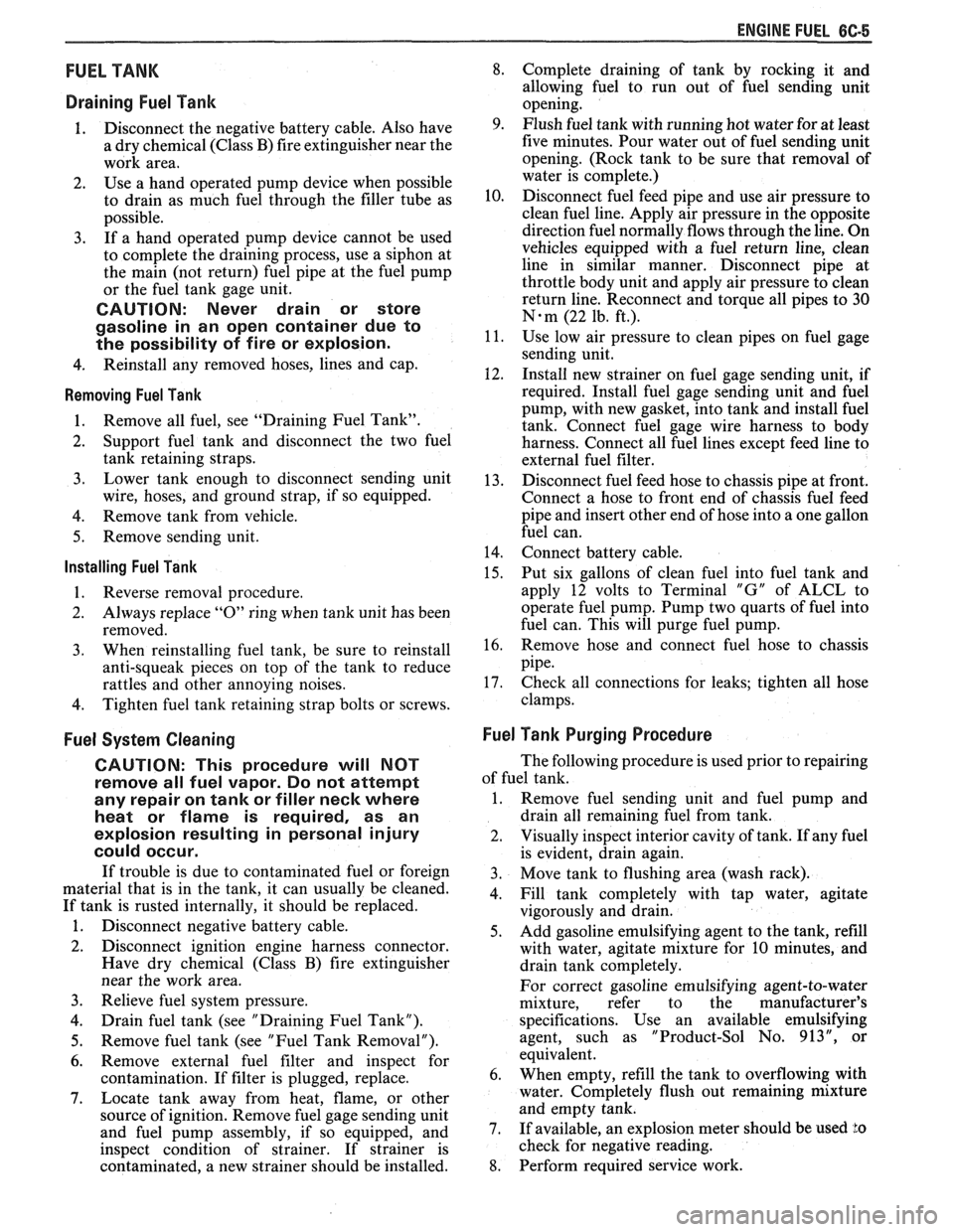
FUEL TANK
Draining Fuel Tank
1. Disconnect the negative battery cable. Also have
a dry chemical (Class B) fire extinguisher near the
work area.
2. Use a hand operated pump device when possible
to drain as much fuel through the filler tube as
possible.
3. If
a hand operated pump device cannot be used
to complete the draining process, use a siphon at
the main (not return) fuel pipe at the fuel pump
or the fuel tank gage unit.
CAUTION: Never drain or store
gasoline in an open container due to
the possibility of fire or explosion.
4. Reinstall any removed hoses, lines and cap.
Removing Fuel Tank
1. Remove all fuel, see "Draining Fuel Tank".
2. Support
fuel tank and disconnect the two fuel
tank retaining straps.
3. Lower tank enough to disconnect sending unit
wire, hoses, and ground strap, if so equipped.
4. Remove tank from vehicle.
5. Remove sending unit.
Installing Fuel Tank
1. Reverse removal procedure.
2. Always replace "0" ring when tank unit has been
removed.
3. When reinstalling fuel tank, be sure to reinstall
anti-squeak pieces on top of the tank to reduce
rattles and other annoying noises.
4. Tighten fuel tank retaining strap bolts or screws.
Fuel System Cleaning
CAUTION: This procedure will NOT
remove all fuel vapor. Do not attempt
any repair
on tank or filler neck where
heat or flame is required, as an
explosion resulting in personal injury
could occur.
If trouble is due to contaminated fuel or foreign
material that is in the tank, it can usually be cleaned.
If tank is rusted internally, it should be replaced.
1. Disconnect negative battery cable.
2. Disconnect ignition engine harness connector.
Have dry chemical (Class B) fire extinguisher
near the work area.
3. Relieve fuel system pressure.
4. Drain fuel tank (see "Draining Fuel Tank").
5. Remove fuel tank (see "Fuel Tank Removal").
6. Remove external fuel filter and inspect for
contamination. If filter is plugged, replace.
7. Locate tank away from heat, flame, or other
source of ignition. Remove fuel gage sending unit
and fuel pump assembly, if so equipped, and
inspect condition of strainer. If strainer is
contaminated, a new strainer should be installed.
8. Complete draining of tank by rocking it and
allowing fuel to run out of fuel sending unit
opening.
9. Flush fuel tank with running hot water for at least
five minutes. Pour water out of fuel sending unit
opening. (Rock tank to be sure that removal of
water is complete.)
10. Disconnect fuel feed pipe and use air pressure to
clean fuel line. Apply air pressure in the opposite
direction fuel normally flows through the line. On
vehicles equipped with a fuel return line, clean
line in similar manner. Disconnect pipe at
throttle body unit and apply air pressure to clean
return line. Reconnect and torque all pipes to 30
N-m (22 1b. ft.).
11. Use low air pressure to clean pipes on fuel gage
sending unit.
112. Install new strainer on fuel gage sending unit, if
required. Install fuel gage sending unit and fuel
pump, with new gasket, into tank and install fuel
tank. Connect fuel gage wire harness to body
harness. Connect all fuel lines except feed line to
external fuel filter.
13. Disconnect fuel feed hose to chassis pipe at front.
Connect a hose to front end of chassis fuel feed
pipe and insert other end of hose into a one gallon
fuel can.
14. Connect battery cable.
15. Put six gallons of clean fuel into fuel tank and
apply 12 volts to Terminal
"G" of ALCL to
operate fuel pump. Pump two quarts of fuel into
fuel can. This will purge fuel pump.
16. Remove hose and connect fuel hose to chassis
pipe.
17. Check all connections
for leaks; tighten all hose
clamps.
Fuel Tank Purging Procedure
The following procedure is used prior to repairing
of fuel tank.
1. Remove fuel sending unit and fuel pump and
drain all remaining fuel from tank.
2. Visually inspect interior cavity of tank. If any fuel
is evident, drain again.
3. Move tank to flushing area (wash rack).
4. Fill tank completely with tap water, agitate
vigorously and drain.
5. Add gasoline emulsifying agent to the tank, refill
with water, agitate mixture for 10 minutes, and
drain tank completely.
For correct gasoline emulsifying agent-to-water
mixture, refer to the
manufacturer's
specifications. Use an available emulsifying
agent, such as "Product-Sol No.
913", or
equivalent.
6. When empty, refill the tank to overflowing with
water. Completely flush out remaining mixture
and empty tank.
7. If available, an explosion meter should be used Lo
check for negative reading.
8. Perform required service work.
Page 437 of 1825
86-8 ENGINE FUEL
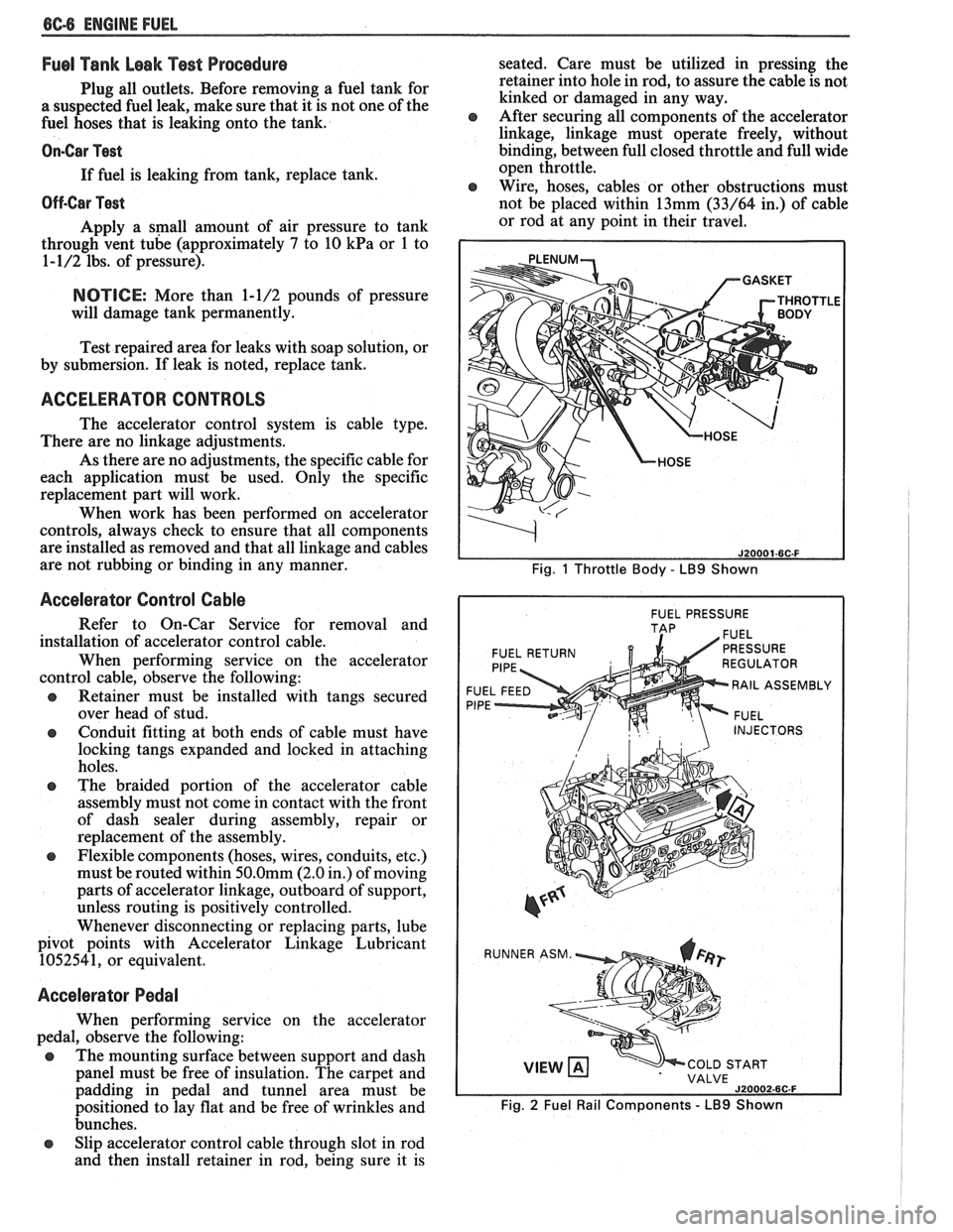
Fuel Tank Leak Test Procedure
Plug all outlets. Before removing a fuel tank for
a suspected fuel leak, make sure that it is not one of the
fuel hoses that is leaking onto the tank.
On-Car Test
If fuel is leaking from tank, replace tank.
Off-Car Pest
Apply a small amount of air pressure to tank
through vent tube (approximately
7 to 10 kPa or 1 to
1-1/2 lbs. of pressure).
NOTICE: More than 1-1/2 pounds of pressure
will damage tank permanently.
Test repaired area for leaks with soap solution, or
by submersion. If leak is noted, replace tank.
ACCELERATOR CONTROLS
The accelerator control system is cable type.
There are no linkage adjustments.
As there are no adjustments, the specific cable for
each application must be used. Only the specific
replacement part will work.
When work has been performed on accelerator
controls, always check to ensure that all components
are installed as removed and that all linkage and cables
are not rubbing or binding in any manner.
Accelerator Control Cable
Refer to On-Car Service for removal and
installation of accelerator control cable.
When performing service on the accelerator
control cable, observe the following:
s Retainer must be installed with tangs secured
over head of stud.
s Conduit fitting at both ends of cable must have
locking tangs expanded and locked in attaching
holes.
s The braided portion of the accelerator cable
assembly must not come in contact with the front
of dash sealer during assembly, repair or
replacement of the assembly.
e Flexible components (hoses, wires, conduits, etc.)
must be routed within
50.0mm (2.0 in.) of moving
parts of accelerator linkage, outboard of support,
unless routing is positively controlled.
Whenever disconnecting or replacing parts, lube
pivot points with Accelerator Linkage Lubricant
1052541, or equivalent.
Accelerator Pedal
When performing service on the accelerator
pedal, observe the following:
s The mounting surface between support and dash
panel must be free of insulation. The carpet and
padding in pedal and tunnel area must be
positioned to lay flat and be free of wrinkles and
bunches.
s Slip accelerator control cable through slot in rod
and then install retainer in rod, being sure it is seated.
Care must be utilized in pressing the
retainer into hole in rod, to assure the cable is not
kinked or damaged in any way.
s After securing all components of the accelerator
linkage, linkage must operate freely, without
binding, between full closed throttle and full wide
open throttle.
e Wire, hoses, cables or other obstructions must
not be placed within 13mm
(33/64 in.) of cable
or rod at any point in their travel.
Fig. 1 Throttle Body - LB9 Shown
I FUEL PRESSURE I
FUEL RETURN
F
RAIL ASSEMBL
P
INJECTORS
VIEW COLD START
VALVE
J20002-6C-F
Fig. 2 Fuel Rail Components - LB9 Shown
Page 962 of 1825
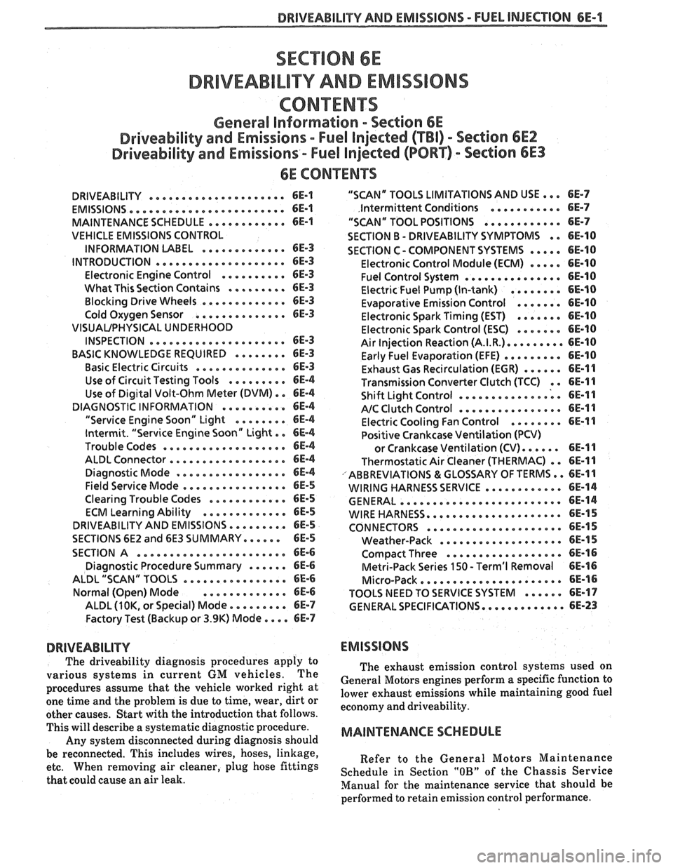
DRIVEABILITY AND EMISSIONS . FUEL INJECIION 6E-1
DRBVEABILIW AND EMISSIONS
CONEENTS
General Information . Section 6E
Driveability and Emissions . Fuel Injected (TBI) . Section 6EZ
Driveability and Emissions . Fuel injected (PORT) . Section 6E3
..................... DRIVEABILITY 6E-1
........................ EMISSIONS 6E-1
MAINTENANCE SCHEDULE ............ 6E-1
VEHICLE EMISSIONS CONTROL
............. INFORMATION UBEL 6E-3
.................... INTRODUCTION 6E-3
.......... Electronic Engine Control 6E-3
What This Section Contains .......*. 6E-3
............. Blocking Drive Wheels 6E-3
.............. Cold Oxygen Sensor 6E-3
VISUAUPHYSICAL UNDERWOOD
..................... INSPECTION 6E-3
BASIC KNOWLEDGE REQUIRED ........ 6E-3
.............. Basic Electric Circuits 6E-3
Use of Circuit Testing Tools ......... 6E-4
Use of Digital Volt-Ohm Meter (DVM) . . 6E-4
DIAGNOSTIC INFORMATION .......... 6E-4
"Service Engine Soon" Light ........ 6E-4
Intermit . "Service Engine Soon" Light . . 6E-4
................... Trouble Codes 6E-4
.................. ALDL Connector 6E-4
Diagnostic Mode ................. 6E-4
Field Service Mode ................ 6E-5
............ Clearing Trouble Codes 6E-5
............. ECM Learning Ability 6E-5
DRIVEABILITY AND EMISSIONS ......... 6E-5
SECTIONS 6E2 and 6E3 SUMMARY ...... 6E-5
SECTION A ....................... 6E-6
Diagnostic Procedure Summary ...... 6E-6
ALDL "SCAN" TOOLS ................ 6E-6
Normal (Open) Mode ............. 6E-6
ALDL (1 OK. or Special) Mode ......... 6E-7
Factory Test (Backup or 3.9K) Mode .... 6E-7
DRIVEABILITY
The driveability diagnosis procedures apply to
various systems in current GM vehicles
. The
procedures assume that the vehicle worked right at
one time and the problem is due to time, wear. dirt or
other causes
. Start with the introduction that follows .
This will describe a systematic diagnostic procedure .
Any system disconnected during diagnosis should
be reconnected
. This includes wires, hoses. linkage.
etc . When removing air cleaner. plug hose fittings
that could cause an air leak
.
"SCAN" TOOLS LIMITATIONS AND USE ... 6E-7
Intermittent Conditions ........... 6E-7
"SCAN" TOOL POSITIONS ............ 6E-7
SECTION B . DRIVEABILITY SYMPTOMS . . 6E-10
SECTION C- COMPONENT SYSTEMS ..... 6E-10
Electronic Control Module (ECM) ..... 6E-10
Fuel Control System ............... 6E-10
Electric Fuel Pump (In-tank) ........ 6E-10
....... Evaporative Emission Control 6E-10
Electronic Spark Timing (EST) ....... 6E-10
....... Electronic Spark Control (ESC) 6E-10
Air Injection Reaction (A.I.R.). ........ 6E-10
......... Early Fuel Evaporation (EFE) 6E-10
Exhaust Gas Recirculation (EGR) ...... 6E-11
Transmission Convefler Clutch (TCC) . . 6E-11
.............. Shift Light Control ; . 6E-I I
................ NC Clutch Control 6E-11
........ Electric Cooling Fan Control 6E-11
Positive Crankcase Ventilation (PCV)
...... or Crankcase Ventilation (CV) 6E-11
Thermostatic Air Cleaner (THERMAC) . . 6E-11
ABBREVIATIONS & GLOSSARY OF TERMS .. 6E-1 1
............ WIRING HARNESS SERVICE 6E-14
......................... GENERAL 6E-14
WIREHARNESS.... ............*.... 6E-15
CONNECTORS .....e..e..ee...~.e.. 6E-15
................... Weather-Pack 6E-15
.................. Compact Three 6E-16
Metri-Pack Series 150 . Terrn'l Removal 6E-16
...................... Micro-Pack 6E-16
...... TOOLS NEED TO SERVICE SYSTEM 6E-17
GENERAL SPECIFICATIONS ............. 6E-23
EMISSIONS
The exhaust emission control systems used on
General Motors engines perform a specific function to
lower exhaust emissions while maintaining good fuel
economy and driveability
.
MAINTENANCE SCHEDULE
Refer to the General Motors Maintenance
Schedule in Section
"OB" of the Chassis Service
Manual for the maintenance service that should be
performed to retain emission control performance
.
Page 1404 of 1825
INSTRUMENT PANEL: GAGES CLUSTER
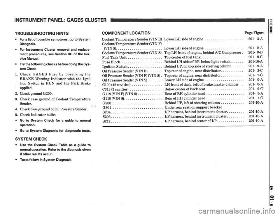
TROUBLESHOOTING HINTS COMPONENT LOCATION Page-Figure
* For a list of possible symptoms, go to System Coolant Temperature Sender (VIN E) Lower LH side of engine ....................
Diangosis. Coolant Temperature Sender (VIN F)
....................... .................... * For Instrument Cluster removal and replace- (VIN 8). Lower
LH side of engine
ment procedures, see Section 8C of the Ser- Coolant Temperature Sender (VIN S) Top LN front of engine, behind A/C Compressor.
.................. ..................... vice Manual. Fuel Tank Unit Top center of fuel tank.
..................... ...... * Try the following checks before doing the Sys- Fuse Block. Behind
LH side of IIP, below light switch.
................. tem Check. Ignition Switch. Behind IIP, on
top side of steering co
....... ........... Oil Pressure Sender (VIN E) Top rear of engine, near distributor. 1. Check GAGES Fuse by observing the . ........... Oil Pressure Sender (VIN F) (VIN 8) Top
rear of engine, near distributor.
BRAKE Warning Indicator with the Igni- Oil Pressure Sender (VIN S) ........ Lower LN side of engine .................... tion Switch in RUN and the Park Brake ................ .. el00 (42 cavities) LN
front of dash, left of brake master cylinder
applied.
................. C313 (3 cavities) Below
center of back seat. ...................
2. Check ground 6200. . 6118 (VIN F) (VIN 8) ............. Rear of RN cylinder head. ...................
.................... ................... 3. Check case ground of Coolant Temperature 6118
(VIN S) Rear
of RH cylinder head.
.......................... ............ Sender. 6200 Behind I/P, left of steering column ' h .......................... 4. Check case ground of Oil Pressure Sender. 6304 Under rear seat,
on support bracket
.......................... S204. IIP harness, behind instrument cluster. ........ 5. Check Indicator bulbs. .......................... ........ S205. I/P harness, behind instrument cluster. * Go to System Check for a guide to normal .......................... S217. I/P harness, behind center of IIP .............. operation.
* Go to Systern Diagnosis for diagnostic tests.
SYSTEM CHECK
* Use the System Check Table as a guide to
normal operation. Refer to the diagnosis given
if other results occur.
* Tests follow in System Diagnosis.
Page 1405 of 1825
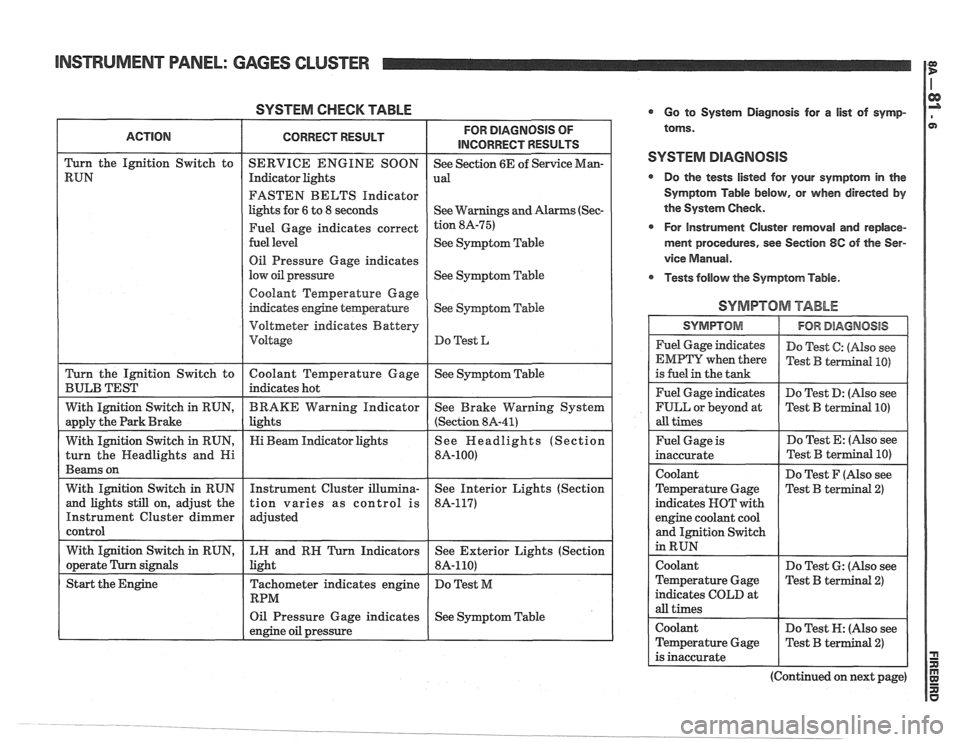
SYSTEM CHECK TABLE
FASTEN BELTS Indicator
lights for
6 to 8 seconds
See
Symptom Table
Oil Pressure Gage indicates
See
Syqtom Table
Coolant Temperature Gage
Voltmeter indicates Battery
Oil Pressure Gage indicates
See Symptom Table
engine oil pressure
L
Go to System Diagnosis for a list of symp-
toms.
SYSTEM DIAGNOSIS
Do the tests listed for your symptom in the
Symptom Table below, or when directed
by
the System Check.
r For Instrument Cluster removal and replace-
ment procedures, see Section
8C of the Ser-
vice
Manual.
Tests follow the Symptom Table.
SYMPTOM TABLE
I SYMPTOM 1 IFORDlAGMOSlS I
Fuel Gage indicates
EMPTY when there
is fuel in the tank
Fuel Gage indicates
FULL or beyond at
all times Do
Test
C: (Also see
Test
B terrnind PO)
Do Test D: (Nso see
Test
B terIllinal PO)
Fuel Gage is
inaccurate
Coolant
Temperature Gage
indicates NOT with
engine coolant cool
and Ignition Switch
in RUN Do
Test E: (Also see
Do Test F (Also see
Test B terminal
2)
coolant
Temperature Gage
indicates COLD at
all times Do
Test
6: (Also see
Test
B terminal 2)
Coolant Do Test N: (Also see
Temperature Gage
Test
B terminal 2)
is inaccurate
(Continued on next page)
Page 1420 of 1825
INSTRUMENT PANEL: DIGITAL CLUSTER a
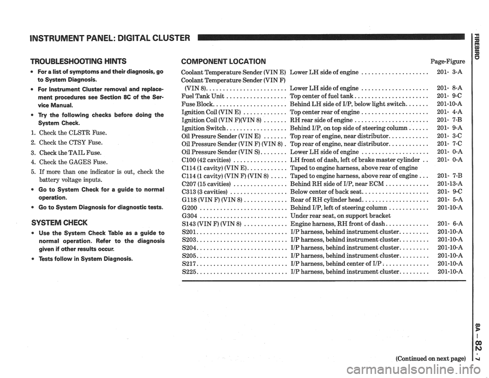
TROUBLESHOOTING HINTS COMPONENT LOCATION u Page-Figure
0 For a list of symptoms and their diagnosis. go
to System Diagnosis
.
0 For Instrument Cluster removal and replace-
ment procedures see Section
86 of the Ser-
vice Manual
.
* Try the following checks before doing the
System Check
.
1 . Check the CLSTR Fuse .
2 . Check the CTSY Fuse .
3 . Check the TAIL Fuse .
Coolant Temperature Sender (VIN E) Lower LH side of engine ....................
Coolant Temperature Sender (VIN F)
(VIN 8)
........................ Lower LH side of engine ....................
Fuel Tank Unit .................. Top center of fuel tank ......................
Fuse Block ...................... Behind LH side of IIP. below light switch .......
Ignition Coil (VIN E) ............. Top center rear of engine ....................
Ignition Coil (VIN F)(VIN 8) ....... RH rear side of engine ......................
Ignition Switch .................. Behind IIP. on top side of steering column ......
Oil Pressure Sender (VIN E) ....... Top rear of engine. near distributor ............
Oil Pressure Sender (VIN F) (VIN 8) . Top rear of engine. near distributor ............
Oil Pressure Sender (VIN S) ........ Lower LH side of engine ....................
................ .. 4 . Check the GAGES Fuse . el00 (42 cavities) LH
front of dash. left of brake master cylinder 201- 0-A
C114
(1 cavity) (VIN E) ............ Taped to engine harness. above rear of engine
5 . If more than one indicator is out. check the C114 (1 cavity) (VIN F) (VIN 8) ..... Taped to engine harness. above rear of engine ... 201- 7-B
battery voltage inputs . . C207 (15 cavities) ................ Behind RH side of IIP near ECM ............. 201-13-A
................. .................... * Go to System Check for a guide to C313 (3 cavities) Below
center of back seat 201- 9-C operation . 6118 (VIN F) (VIN 8) ............. Rear of RH cylinder head .................... 201- 5-A
0 Go to System Diagnosis for diagnostic tests . 6200 .......................... Behind IIP. left of steering column ............ 201-10-A
6304
.......................... Under rear seat. on support bracket
SYSTEM CHECK S143 (VIN F) (VIN 8) ............. Engine harness. RH front of dash ............. 201- 6-A
0 Use the System Check able as a guide to S201 ........................... IIP harness. behind instrument cluster ......... 201-10-A
normal operation . Refer to the diagnosis S203 ........................... I/P harness. behind instrument cluster ......... 201-10-A
........................... ......... given if other results occur . S204 IIP harness. behind instrument cluster 201-10-A
........................... ......... Tests follow in System Diagnosis . S205 IIP harness. behind instrument cluster 201-10-A
S217 ........................... IIP harness. behind center of IIP .............. 201-10-A
S225 ........................... IIP harness. behind instrument cluster ......... 201-10-A
(Continued on next page)
Page 1736 of 1825
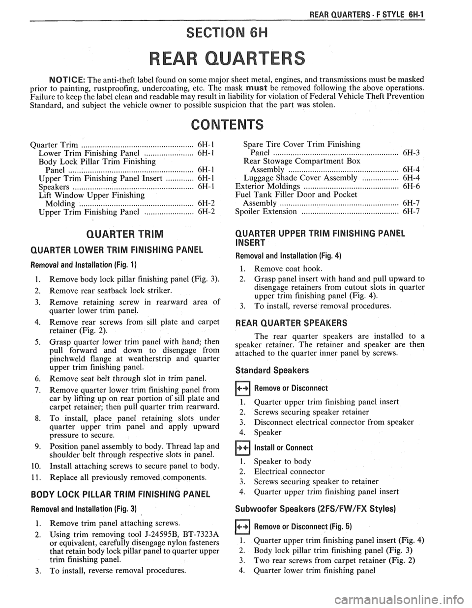
REAR QUARTERS - F STYLE 8H-1
SECTION 6H
REAR QUARTERS
NOTICE: The anti-theft label found on some major sheet metal, engines, and transmissions must be masked
prior to painting, rustproofing, undercoating, etc. The mask
must be removed following the above operations.
Failure to keep the label clean and readable may result in liability for violation of Federal Vehicle Theft Prevention
Standard, and subject the vehicle owner to possible suspicion that the part was stolen.
CONTENTS
Quarter Trim .................................................... 6H- 1
Lower Trim Finishing Panel ....................... 6H- 1
Body Lock Pillar Trim Finishing
Panel
., ....................................................... 6H- 1
Upper Trim Finishing Panel Insert ............. 6H- 1
....................................................... Speakers 6H- 1
Lift Window Upper Finishing
Molding
..................................................... 6H-2
....................... Upper Trim Finishing Panel 6H-2
QUARTER TRlM
QUARTER LOWER TRlM FINISHING PANEL
Removal and Installation (Fig. 1)
Remove body lock pillar finishing panel (Fig. 3).
Remove rear
seatback lock striker.
Remove retaining screw in rearward area of
quarter lower trim panel.
Remove rear screws from sill plate and carpet
retainer (Fig.
2).
Grasp quarter lower trim panel with hand; then
pull forward and down to disengage from
pinchweld flange at weatherstrip and quarter
upper trim finishing panel.
Remove seat belt through slot in trim panel.
Remove quarter lower trim finishing panel from
car by lifting up on rear portion of sill plate and
carpet retainer; then pull quarter trim rearward.
To install, place panel retaining slots under
quarter upper trim panel and apply upward
pressure to secure.
Position panel assembly to body. Thread lap and
shoulder belt through respective slots in panel.
Install attaching screws to secure panel to body.
Replace all previously removed components.
BODY LOCK PILLAR TRlM FINISHING PANEL
Removal and lnstallation (Fig. 3)
1. Remove trim panel attaching screws.
2. Using trim removing tool J-24595B, BT-7323A
or equivalent, carefully disengage nylon fasteners
that retain body lock pillar panel to quarter upper
trim finishing panel.
3. To install, reverse removal procedures. Spare
Tire Cover Trim Finishing
Panel
........................................................ 6H-3
Rear Stowage Compartment Box
Assembly
................................................... 6H-4
Luggage Shade Cover Assembly
................. 6H-4
Exterior Moldings
........................................... 6H-6
Fuel Tank Filler Door and Pocket
Assembly
....................................................... 6H-7
Spoiler Extension
............................ .. ........... 6H-7
QUARTER UPPER TRlM FINISHING PANEL
INSERT
Removal and Installation (Fig. 4)
1. Remove coat hook.
2. Grasp panel insert with hand and pull upward to
disengage retainers from cutout slots in quarter
upper trim finishing panel (Fig. 4).
3. To install, reverse removal procedures.
REAR QUARTER SPEAKERS
The rear quarter speakers are installed to a
speaker retainer. The retainer and speaker are then
attached to the quarter inner panel by screws.
Standard Speakers
Remove or Disconnect
1. Quarter upper trim finishing panel insert
2. Screws securing speaker retainer
3. Disconnect electrical
connector from speaker
4. Speaker
Install or Connect
1. Speaker to body
2. Electrical connector
3. Screws securing speaker to retainer
4. Quarter upper trim finishing panel insert
Subwoofer Speakers (2FS/FW/FX Styles)
Remove or Disconnect (Fig. 5)
1.
Quarter upper trim finishing panel insert (Fig. 4)
2. Body lock pillar trim finishing panel (Fig. 3)
3. Two rear screws from carpet retainer (Fig.
2)
4.
Quarter lower trim finishing panel
Page 1742 of 1825
REAR QUARTERS - F STYLE 6N-7
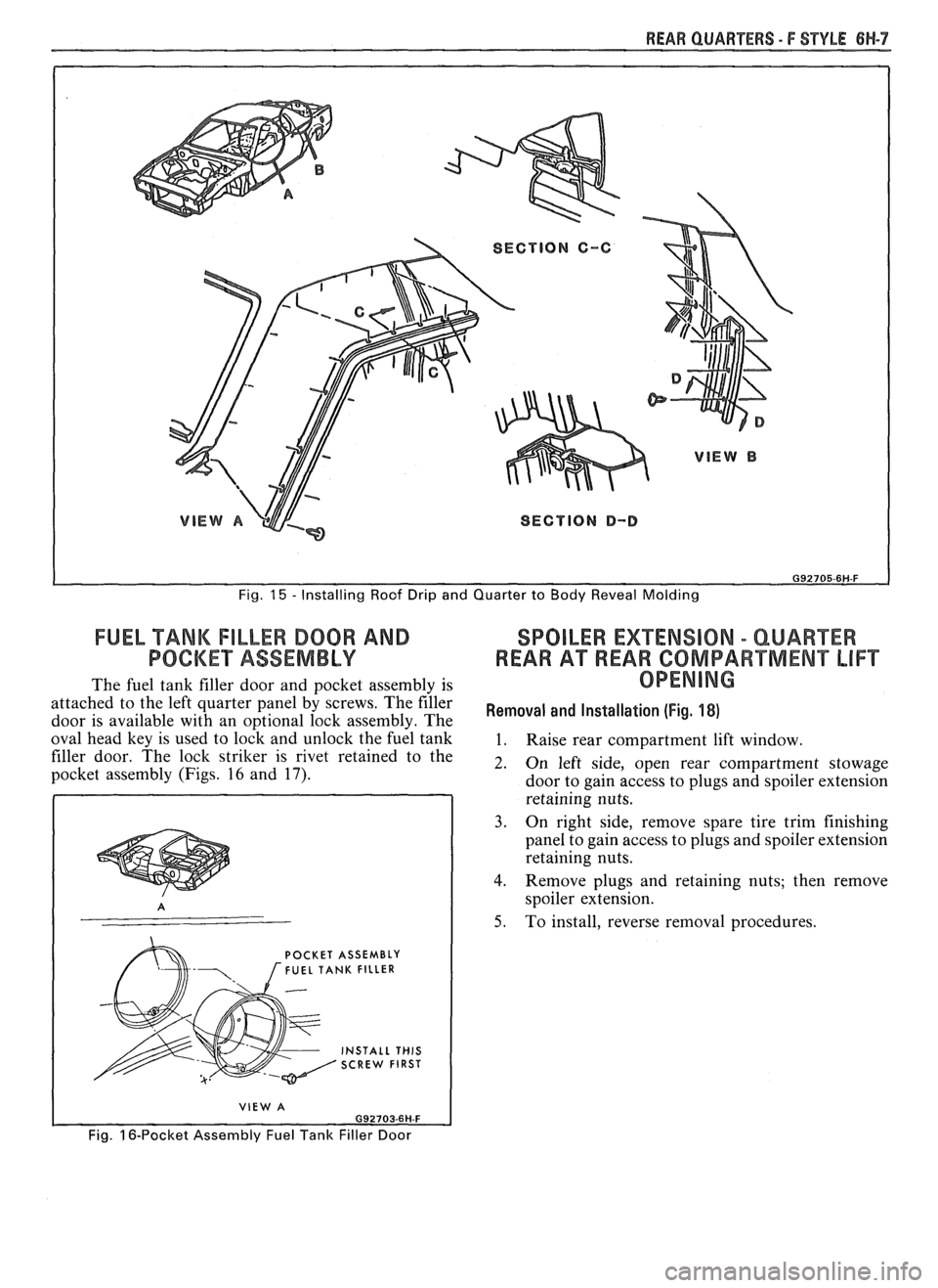
Fig. 15 - Installing Roof Drip and Quarter to Body Reveal Molding
FUEL TANK FILLER DOOR AND SPOILER EXTENSION - QUAREER
POCKET ASSEMBLY REAR A"FREAR COMPARTMENT LIFT
The fuel tank filler door and pocket assembly is OPENING
attached to the left quarter panel by screws. The filer Removal and (Fig, door is available with an o~tional lock assemblv. The
oval head key is used to
loik and unlock the fuil tank 1. Raise rear compartment lift window.
filler door. The lock striker is rivet retained to the
2. 0, left side, open rear compartment stowage pocket assembly (Figs. 16 and 17). door to gain access to plugs and spoiler extension
retaining nuts.
3. On right side, remove spare tire trim finishing
panel to gain access to plugs and spoiler extension
retaining nuts.
4. Remove plugs and retaining nuts; then remove
spoiler extension.
5. To install, reverse removal procedures.
POCKET ASSEMBLY FUEL TANK FILLER
INSTALL THIS SCREW FIRST
VIEW A
Fig. 16-Pocket Assembly Fuel Tank Filler Door
Page 1812 of 1825
BODY INDEX . F STYLE 1
BODY INDEX
a
ABS and Polypropylene Plastic Test .............. 1 H- 13
Actuator. Power Door Lock
.......................... 5H-20
Adhesive-backed Moldings. Emblems. Name Plates
.................................................... 7FI-1
Adhesive Body Side Molding ............................ 1H-3
Adhesive Service
Kit . Stationary Glass ........... 2H-2
Adjuster
. Manual and Power Seats .......... 9H.12. 15
Alignment Checking
. Underbody .................... 3H-1
Anticorrosion Treatment
................................... 1H-4
Armrest
. Door ................................................. 5H-1
Assembling and Coding
Lock Cylinders ............ 1H-1
B
Body
Lock Pillar Trim Finishing Panel
................. 6H-1
Side Hinge Strap
......................................... 5H-10
I 'entilation ................................... .... ............... 4H-1
bonded
Rearview Mirror Support .................... 2H-5
Bucket Seat. High Performance
...................... 9H- 15
C
............................. Cable . Hood Latch Release 4H-1
Cargo Light
. Rear Compartment .................. 7H- 13
..................................................... Carpet 3H.2,7 H. 13
Center High Mounted Stop Lamp
.................. 7H-16
Child Seat
........................................................... 9H-2
Chip Resistant Plastisol Material
...................... 1H-8
...................................... Coding Lock Cylinders 1
H- 1
Colors for Interior Plastic Parts ...................... 1H-14
............................. Compartment Lift Window 7H-2
Garnish Molding
........................................ 8H-2
Glass
Replacement/Adjustment .................... 7H-5
Release Solenoid
.......................................... 7H-9
.......................................................... Spoiler 7H- 13
.................................................. Trim Panel 7H- 1 1
................................................ Weatherstrip 7H- 1 1
Cwnecting/Locking Rods, Doors .................. 5H- 16 I . itrol Arm Knob . Manual Seat .................. 9H-10
Convertible Top
................................................ 8H-7
Cover Assembly
. Luggage Shade ..................... 6H-4
................................................... Cutting Keys 1H- 1
D
............................ Deflector. Inner Panel Water 5H-6
Defogger
. Rear Window .................................. 2H-6
Diagnosis Chart
................................... Manual Seat Adjusters 9H-8
Power Six-Way Seat Adjuster
....................... 9H-9
Dome Lamps
...................................................... 8H-1
Boor Armrest and Pull Handle
.............................. 5H-1
Bell Crank
.................................................... 5H-20
Hardware Lubrication
................................. 5H- 19
Hinges
............................................................. 5H-7
Inner Panel Water Deflector
......................... 5H-6
Inside Handles and Cover Plate
.................... 5H-1
Inside Remote Handle
................................. 5H-16
Insulator Pads
............................................. 5H-6
Jamb Switch
................................................. 5H-19
Lock
.............................................................. 5H- 19
Lock Knob
..................................................... 5H-2
................................................. Lock Striker 5H- 17
............................................ Outside Handle 5H- 16
Outside Mirror
................................... 5H- 1.5 H. 15
Trim Assemblies
............................................ 5H-2
................................................... Weatherstrip 5H-4
................................................. Wedge Plate 5H-18
....................................... Window Assembly 5H- 10
...................................... Belt Sealing Strips 5H-6
........................................ Filler Assembly 5H- 13
.......................................... Front Up Stop 5H-14
................................ Rear Guide Channel 5H- 15
Regulator/Motor .................................... 5H-11
...................................... Door Side Hinge Strap 5H-8
Emblems.
Name Plates and Moldings .
Rear Compartment ........................................ 7H-I
. ....................................... Emblems Roof Panel 8H-3
. ............................. Exterior Lamps Rear End 7H-15
Exterior Moldings
Doors
............................................................ 5H-20
............................................... Rear Quarters 6H-6
.............................................................. Roof 8W-3
Finishing Panel. Quarter Lower Trim .............. 6H-1
Flexible Exterior Plastic Parts
.......................... 1H-9 .
.................................. E/P or TPO Repair 1H-12
Floor Carpet
................................................... 3H-2
Floor Pan Insulators
............................ .. ........ 3H-1
Folding Rear
Seatback ........................ ... ...... 9H- 19
Formed Headlining
.......................................... 8H-1
........................................................ Front End 4H-1
.......................................................... Front Seat 9H-5
............ Adjuster Assembly. Manual/Power 9H- 1 1
................................................... Adjustment 9H- 10
........................... Assembly. Manual/Power 9H- 1 1
................................................................ Back 9H-7
. ................................ Belt Warning System .... 9H-1
................... High Performance Bucket Seat 9H-
15
............................... Manual Control Knob 9H- 10
................................. Manual Recliner Check 9H-7
........................................ Power Seat Switch 9H- 15
............................................. Reclining Back 9H-6
............................... Seatback Head Restraint 9H-5
.................. Seatback Lock Striker/Bar Stop 9H-15
................................. Shoulder Belt Retractor 9H-2
................................. Six-way Seat Adjuster 9H-12
................................... Torque Specifications 9H-8
Fuel Tank Filler
Door/Pocket ........................ 6H-7
Gas Support
. Compartment Lift
........................................................... Window 7H-7
............................... General Body Construction 3H-1
.......................................... General Information 1H-1
Glass Installation
........................................... Extended Method 2H-4
................................................. Short Method 2H-3
...................................... Glass Scratch Removal 2H- 1