fuse PONTIAC FIERO 1988 Service Repair Manual
[x] Cancel search | Manufacturer: PONTIAC, Model Year: 1988, Model line: FIERO, Model: PONTIAC FIERO 1988Pages: 1825, PDF Size: 99.44 MB
Page 30 of 1825
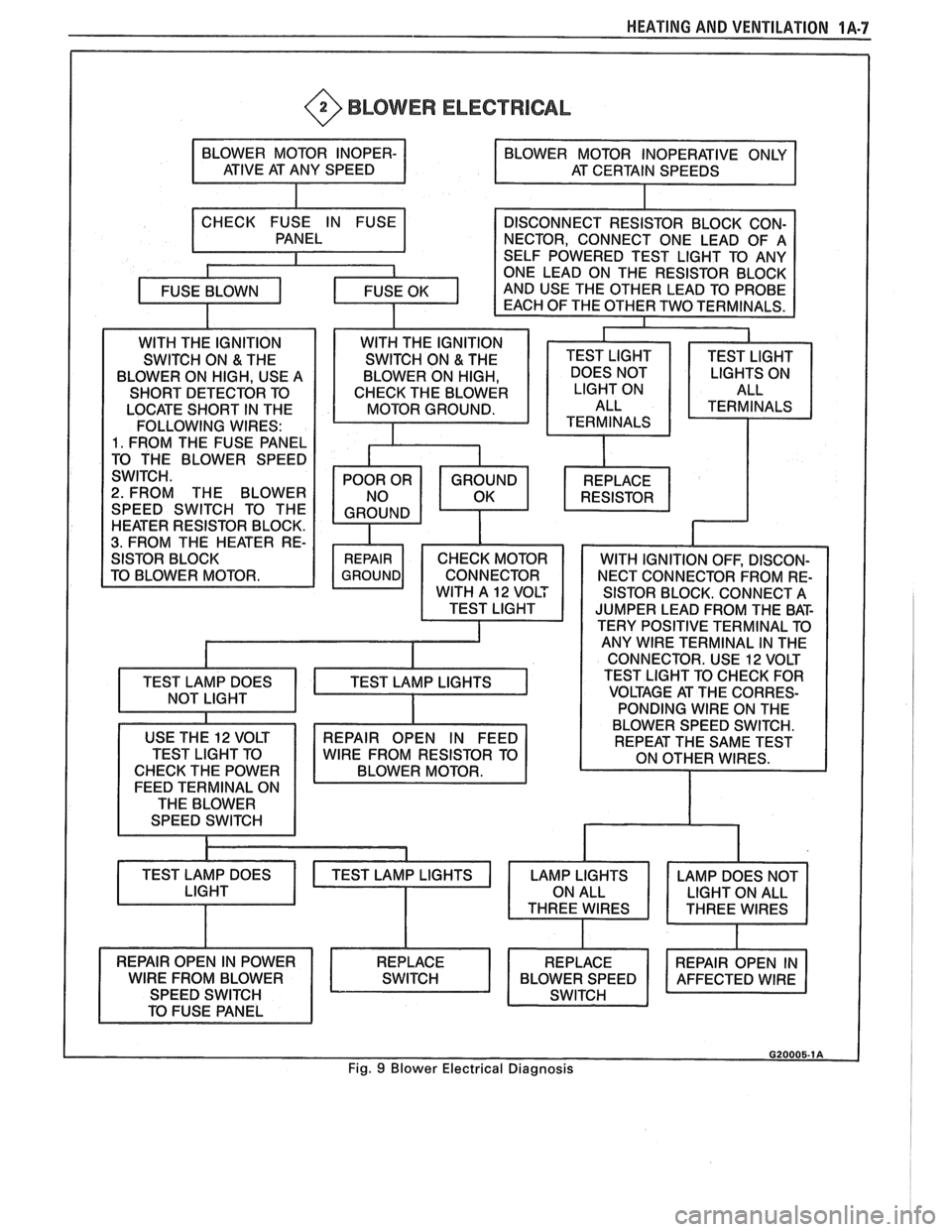
HEATING AND VENTILATION 1A-7
@ BLOWER ELECTRICAL
LOCATE SHORT IN THE
FOLLOWING WIRES:
1. FROM THE FUSE PANEL
2. FROM THE BLOWER
SPEED SWITCH TO THE
HEATER RESISTOR BLOCK.
3. FROM THE HEATER RE-
SISTOR BLOCK. CONNECT A
JUMPER LEAD FROM THE BAT-
TERY POSITIVE TERMINAL TO
ANY
WlRE TERMINAL IN THE
CONNECTOR. USE
12 VOLT
TEST LIGHT TO CHECK FOR
VOLTAGE AT THE CORRES-
PONDING WIRE ON THE
USE THE
12 VOLT
TEST LIGHT TO
CHECK THE POWER
FEED TERMINAL ON
THE BLOWER
SPEED SWITCH
TEST LAMP DOES BLOWER
SPEED SWITCH.
REPAIR OPEN IN FEED
WlRE FROM RESISTOR TO
BLOWER MOTOR.
Fig. 9 Blower Electrical Diagnosis
Page 51 of 1825
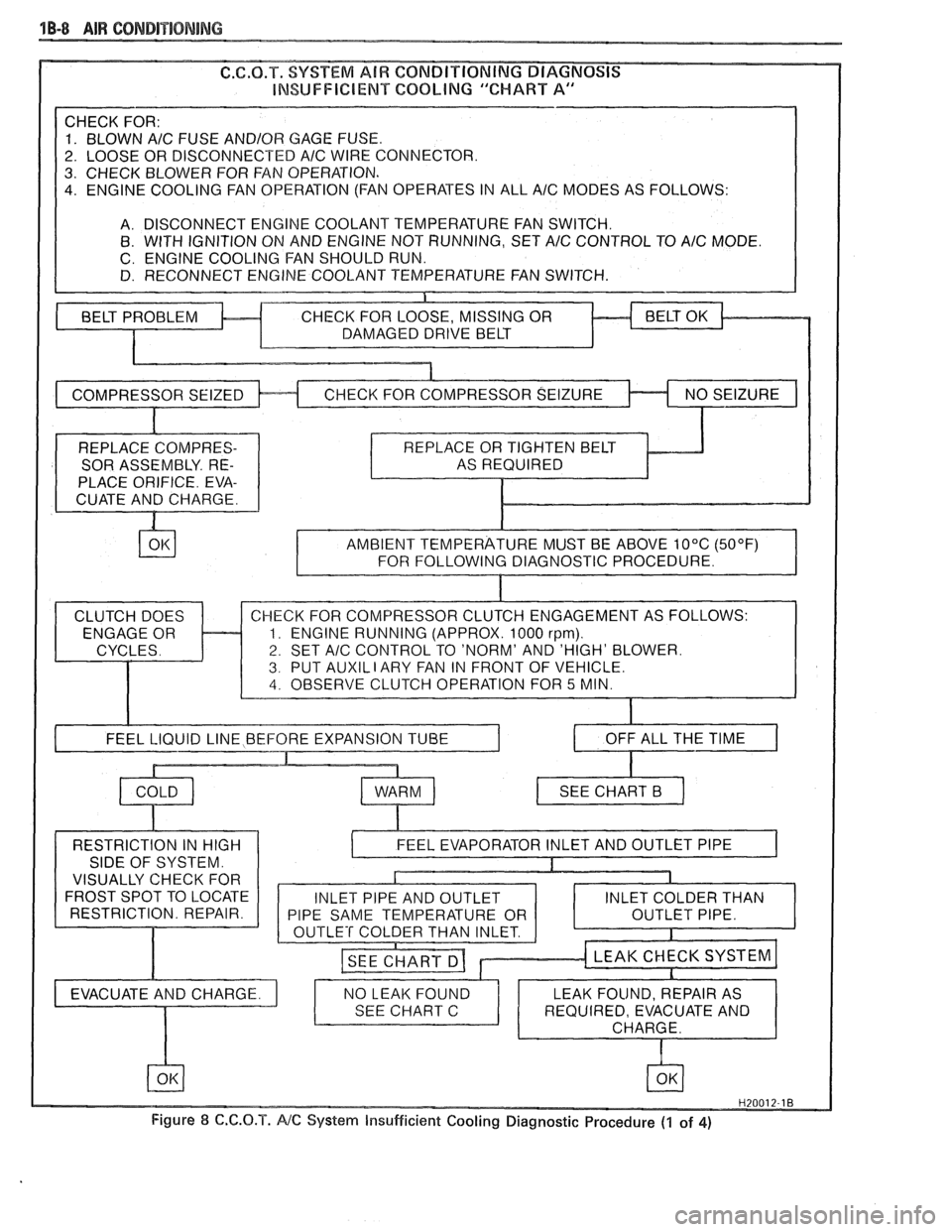
1B-8 AIR CONDITIONING
INSUFFICIENT COQblNG "CHART A
A/C FUSE AND/OR GAGE FUSE.
OR DISCONNECTED
AlC WIRE CONNECTOR.
. CHECK BLOWER FOR FAN OPERATION.
. ENGINE COOLING FAN OPERATION (FAN OPERATES IN ALL A/C MODES AS FOLLOWS:
A. DISCONNECT ENGINE COOLANT TEMPERATURE FAN SWITCH.
8. WITH IGNITION ON AND ENGINE NOT RUNNING, SET A/C CONTROL TO A/C MODE.
C. ENGINE COOLING FAN SHOULD RUN.
D. RECONNECT ENGINE COOLANT TEMPERATURE FAN SWITCH.
REPLACE COMPRES-
SOR ASSEMBLY. RE-
PLACE ORIFICE. EVA-
CUATE AND CHARGE. AS
REQUIRED
AND 'HIGH' BLOWER.
T
AUXIL I ARY FAN IN T OF VEHICLE.
I OFF ALL THE TIME I
RESTRICTION IN HIGH
SIDE OF SYSTEM.
VISUALLY CHECK FOR
FROST SPOT TO LOCATE
RESTRICTION. REPAIR.
Figure
8 C.C.O.T. NC System Insufficient Cooling Diagnostic Procedure (1 of 4)
Page 132 of 1825
STEERING, SUSPENSION, TIRES AND WHEELS DIAGNOSIS 3-7
e To determine if turn signal switch is inoperative,
substitute new turn signal switch into circuit and
operate switch by hand.
If the car's lights operate
normally, turn signal switch is inoperative.
Front Or Rear Turn Signal Lights Not Flashing
Inspect
s Burned-out or damaged turn signal bulb
e High resistance conection to ground at bulb
socket
s Loose chassis-to-column connector. Disconnect
column-to-chassis connector and connect new
turn signal switch into system and operate switch
by hand.
A. If turn signal lights are now on and flashing,
turn signal switch is inoperative.
B. If car lights do not operate, refer to Section
8A
for electrical diagnosis.
Turn Indicator Panel Lights
Inspect
Burned out bulbs or opens, grounds in the wiring
harness from the front turn signal bulb socket to the
indicator lights. Refer to Section
8A for electrical
diagnosis.
Stop Light Mot On When Turn Indicated
Inspect
s Loose column-to-chassis connection
e Disconnect the column-to-chassis connector and
connect the new turn signal switch into the
system and operate the switch by hand.
A. If the brake lights work when the switch is
in the turn position, the turn signal switch
is inoperative.
B. If the brake lights do not work, refer to Section
8A for electrical diagnosis.
Turn Signal Lights Flash Very Slowly
e Loose chassis-to-column connection
a Disconnect the column-to-chassis connector and
connect a new turn signal switch into the system
and operate the switch by hand.
A. If the lights flash at a normal rate, the turn
signal switch is inoperative.
B. If the Lights still flash very slowly, refer to
Section
8A for electrical diagnosis.
Hazard Signal Lights Will Not Flash - Turn
Signal Functions Normally
~"SPBC~
a Blown fuse
Inoperative hazard warning flasher
e Loose chassis-to-column connection
s Disconnect the column-to-chassis connector and
connect a new turn signal switch into the system,
then press in the hazard warning button and
watch the hazard warning lights.
A. If the lights now work normally, the turn
signal switch is inoperative.
B. If the lights do not flash, check the wiring
harness. Refer to Section
8A for electrical
diagnosis.
IGNITION SWITCH
Electrical System Will Not Function
Damaged ign~rion switch
e Ignition switch not adjusted properly
e Loose connector at the ignition switch
Switch Will Not Turn
Inspect
Damaged ignition switch
Switch Cannot Be Set Correctly
Inspect
Switch actuator rod deformed
e Sector to rack engaged in wrong tooth
KEY REMINDER
Figs. 1 through 11 ,
Weminder Continues To Operate With Key Out,
But Stops When Driver's Door Is Closed
e Chips, foreign material in lock cylinder bore
Sticky lock cylinder actuator tip
Damaged or broken reminder switch
Reminder Does Not Sound With Key Fully
Inserted In Lock Cylinder And The Driver's Door
Open
Inspect
1. Power not available to reminder. Refer to Sec-
tion
8A for electrical diagnosis.
2. Open in chassis wiring. Check by separating
chassis-to-column connector. Connect terminals
"E" and "F" female contacts on the chassis
connector (a bent paper clip will work). If the
reminder sounds, repair chassis wiring. If the
reminder does not sound, go to Step
A.
A. Connect a continuity meter (light) to the
male
"E" and "F" column connector
contacts. Push the key all the way into the
lock cylinder. If the light is on when the key
Page 255 of 1825
4819 REAR AXLE
bears against the inner race of the front bearing and a
shoulder on the pinion stem. This spacer is used to
enable accurate bearing pre-load adjustment and
maintain a pre-load on both front and rear pinion
bearings, Adjustment of the fore and aft position of the
pinion is obtained by placing a shim between the rear
pinion bearing cup and axle housing. The differential
case is of two-piece construction and is supported in
the carrier by two tapered roller side bearings. Pre-load
rear axle case by inserting shims between the bearings
and the carrier. The rear axle case assembly is
positioned for proper ring gear to pinion backlash by
varying the shim thickness from side to side. The ring
gear is bolted to the case. Two side gears have splined
bores for driving the axle shafts. They are positioned
to turn in counterbored cavities in the case. The four
rear axle pinions have smooth bores and are held in
position by a pinion cross shaft, mounted and locked
in the rear axle case. All six gears are in mesh with each
other and because the pinion gears turn freely on their
shaft, they act as idler gears when the rear wheels are
turning at different speeds. The pinions and side gears
are backed by steel thrust washers.
LIMITED-SLIP REAR AXLE
The operation of the Limited-Slip differential is
the same as the standard differential, except that there
is additional friction provided by the conical clutches.
Under ordinary driving and cornering conditions, the
cones slip, allowing the outside wheel to turn faster
than the inner. Under poor traction conditions, such as
ice, snow, or loose gravel under one driving wheel, the
increased friction provided by the cones increases the
driving torque available to the wheel with the better
traction. The cones are spring loaded to provide the
increased driving torque under extremely low traction
conditions.
Operation
When the vehicle turns a corner, the outer rear
wheel must turn faster than the inner wheel. The inner
wheel, turning slower than the outer wheel, slows its
differential side gear (as the axle shaft is splined to the
side gear) and the differential pinion gears will roll
around the slowed differential side gear, driving the
other differential side gear and wheel faster.
DIAGNOSIS AND TESTING
Many noises reported as coming from the rear
axle assembly actually originate from other sources
such as tires, road surfaces, front wheel bearings, axle
bearing, engine, transmission, muffler or body
drumming. A thorough and careful check should be
made to determine the source of the noise before
disassembling the rear axle. Noise which originates in
other places cannot be corrected by adjustment or
replacement of parts in the differential. It should also
be remembered that rear axle gears, like any other
mechanical device, are not absolutely quiet and should
be accepted as being commercially quiet unless some
abnormal noise is present.
To make a systematic check for axle noise under
standard conditions, observe the following:
1. Select a level smooth asphalt road to reduce tire
noise and body drumming.
2. Check rear axle lubricant to assure correct level,
then drive car far enough to thoroughly warm up
rear axle lubricant, approximately 10 miles.
3. Note speed and RPM at which noise occurs. Stop
car and put transmission in neutral. Run engine
slowly up and down through engine speeds,
corresponding to car speed at which noise was
most pronounced, to determine if it is caused by
exhaust, muffler roar or other engine conditions.
4. Tire noise changes with different road surfaces,
but rear axle noise does not. Temporarily
inflating all tires to approximately 50 pounds
pressure
for test purposes only will materially
alter noise caused by tires, but will not affect noise
caused by rear axle. Rear axle noise usually stops
when coasting at speeds under 30 miles per hour;
however, tire noise continues, but with lower
tone, as car speed is reduced. Rear axle noise
usually changes when comparing acceleration
and coast, but tire noise remains about the same.
Distinguish between tire noise and rear axle noise
by noting if noise varies with various speeds or
sudden acceleration and deceleration; exhaust
and axle noise show variations under these
conditions while tire noise remains constant and
is more pronounced at speeds of 20 to 30 miles
per hour. Further check for tire noise by driving
car over smooth pavements or dirt roads (not
gravel) with tires at normal pressure. If noise is
caused by tires, it will noticeably change or
disappear and reappear with changes in road
surface.
5. Loose or rough front wheel bearings will cause
noise which may be confused with rear axle
noises; however, front wheel bearing noise does
not change when comparing drive and coast.
Light application of brakes while holding car
speed steady will often cause wheel bearing noise
to diminish, as this takes some weight off the
bearing. Front wheel bearings may be easily
checked for noise by jacking up the wheels and
spinning them, also by shaking wheels to
determine if bearings are loose.
6. Rear suspension rubber bushings and spring
insulators dampen out rear axle noise when
correctly installed. Check to see that no metallic
contact exists between the spring and spring seat
opening in frame or between upper and lower
control arm bushings and frame or axle housing
brackets. The track bar and torque arm must be
bolted securely. Metal-to-metal contact at those
points may result in telegraphing road noise and
normal axle noise which would not be
objectionable if dampened by bushings.
AXLE NOISES
After the noise has been determined as being in
the axle by following the above appraisal procedure,
the type of axle noise should be determined to aid in
making repairs if necessary.
Page 257 of 1825
481-4 REAR AXLE
Gear Noise
Gear noise (whine) is audible from 20 to 55 mph
under four driving conditions:
1. Light Acceleration - Accelerate slowly.
2. Road Load
- Car
driving load or constant speed.
3. Float - Using enough throttle to keep the car from
driving the engine
- car slows down gradually but
engine still pulls slightly.
4. Coast - Throttle closed and car in gear.
Bearing Noise
Bad bearings generally produce more of a rough
growl or grating sound, rather than the whine typical
of gear noise. Bearing noise frequently "wow-wows" at
bearing rpm, indicating a defective pinion or rear axle
case side bearing. This noise could easily be confused
with rear wheel bearing noise. Inspect and replace as
required.
Rear Wheel Bearing Noise
A rough rear wheel bearing produces a noise
which continues with car coasting at low speed and
transmission in neutral. Noise may diminish some by
gentle braking. With rear wheels jacked up, spin rear
wheels by hand while listening at hubs for evidence of
rough (noisy) wheel bearing.
Knock At Low Speeds
Low speed knock can be caused by worn
universal joints or a side gear hub counterbore in a case
that has worn oversize. Inspect and replace universal
joint or case and side gear as required.
Backlash Clunk
Excessive clunk with acceleration and deceleration
is caused by worn differential pinion gear shaft, excessive
clearance between axle shaft and side gear splines, exces-
sive clearance between side gear hub and counterbore in
case, worn pinion and side gear teeth, worn thrust washers
and excessive drive pinion and ring gear backlash. Re-
move worn parts and replace as required, selecting close
fitting parts when possible. Adjust pinion and ring gear
backlash.
DIAGNOSIS
1. Noise
is the same in "Light Acceleration" or
"Coast".
a. Road noise.
b. Tire noise.
c. Front wheel bearing noise.
d. Rear axle bearing noise.
2. Noise changes on a different type of road.
a. Road noise.
b. Tire noise.
3. Noise tone lowers as car speed is lowered.
a. Tire noise.
b. Front
wheel bearings and rear axle bearings.
c. Gear noise.
4. Similar noise is produced with car standing and
driving. a.
Engine noise.
b. Transmission noise.
c. Exhaust noise.
5. Vibration.
a. Rough rear axle bearing.
b. Unbalanced or damaged propeller shaft.
c. Tire unbalance.
d. Worn universal joint in propeller shaft.
e. Mis-indexed propeller shaft at pinion
flange.
f. Pinion flange runout too great.
6. A knock or click approximately every two
revolutions of the rear wheel.
a. A rear axle bearing.
b. Worn case.
7. Noise most pronounced on turns.
a. Rear axle side gear and pinion noise,
differential gear noise.
b. Axle bearings.
8. A continuous low pitch whirring or scraping
noise starting at relatively low speed.
a. All bearing noise.
9. Drive noise, coast noise or float noise.
a. Ring
and pinion gear noise.
b. Front
pinion bearing noise, coast or drive.
c. Axle bearing noise.
10. Clunk
on
acceleration or deceleration.
a. Worn
rear axle pinion shaft splines.
b. Side
gear hub counterbore in case worn
oversize.
c. Worn U-joints.
d. Excessive transmission backlash.
e. Worn axle shaft splines.
11. Chatter on turns.
a. Wrong
lube in rear axle.
b. Clutch
cone worn or spalled.
12. Clunk
or knock on rough road operation.
a. Worn suspension bushings.
PRE-REPAIR INVESTIGATION AND TROUBLE
DIAGNOSIS
A carefull diagnosis of the rear axle prior to
disassembly will often reveal valuable information as to
the extent and type of repairs or adjustments necessary.
Since frequent causes of axle noises are improper
backlash, pinion bearing pre-load, or side bearing
pre-load, or a combination, a few simple adjustments
may be all that are necessary to correct a problem.
Before disassembling the rear axle, the following
checks should be made with the results recorded and
analyzed: 1) Backlash;
2) Total Assembly Preload; 3)
Tooth Contact Pattern Test; 4) Fluid Level; and 5)
Fluid Contamination.
If axle shaft end play is excessive then check
bearings, retainer, and bolts securing backing plate.
The axle bearings could be worn and need replacement.
The four bolts or nuts securing the brake backing plate
may be loose, stripped, or missing. If the inner bearing
retainer worked loose it must be replaced.
Use care at all times to keep dirt and other foreign
matter, such as grinder dust, soot or sand, away from
differential to prevent possibility of subsequent failure.
Page 276 of 1825
REAR AXLE 4B-3
Noise which originates in other places cannot be
corrected by adjustment or replacement of parts in the
differential. It should also be remembered that rear
axle gears, like any other mechanical device, are not
absolutely quiet and should be accepted as being
commercially quiet unless some abnormal noise is
present.
To make a systematic check for axle noise under
standard conditions, observe the following:
1. Select a level smooth asphalt road to reduce tire
noise and body drumming.
2. Check rear axle lubricant to assure correct level,
then drive car far enough to thoroughly warm up
rear axle lubricant.
3. Note speed and RPM at which noise occurs. Then
stop car and with automatic transmission in neutral,
run engine slowly up and down through engine speeds, corresponding to car speed at which noise
was most pronounced, to determine if it is caused by
exhaust, muffler roar or other engine conditions.
4. Tire noise changes with different road surfaces,
but rear axle noise does not. Temporarily
inflating all tires to approximately 50 pounds
pressure for
test purposes only will materially
alter noise caused by tires, but will not affect noise
caused by rear axle. Rear axle noise usually stops
when coasting at speeds under 30 miles per hour;
however, tire noise continues, but with lower
tone, as car speed is reduced. Rear axle noise
usually changes when comparing acceleration
and coast, but tire noise remains about the same.
Distinguish between tire noise and rear axle noise
by noting if noise varies with various speeds or
sudden acceleration and deceleration; exhaust
and axle noise show variations under these
conditions while tire noise remains constant and
is more pronounced at speeds of 20 to 30 miles
per hour. Further check for tire noise by driving
car over smooth pavements or dirt roads (not
gravel) with tires at normal pressure. If noise is
caused by tires, it will noticeably change or
disappear and reappear with changes in road
surface.
5. Loose or rough front wheel bearings will cause
noise which may be confused with rear axle
noises; however, front wheel bearing noise does
not change when comparing drive and coast.
Light application of brakes while holding car
speed steady will often cause wheel bearing noise
to diminish, as this takes some weight off the
bearing. Front wheel bearings may be easily
checked for noise by jacking up the wheels and
spinning them, also by shaking wheels to
determine if bearings are loose.
6. Rear suspension rubber bushings and spring
insulators dampen out rear axle noise when
correctly installed. Check to see that no metallic
contact exists between the spring and spring
opening in frame or between upper and lower
control arm bushings and frame or axle housing
brackets.
Metal-to-metal contact at those points
may result in telegraphing road noise and normal axle
noise which would not be objectionable if
dampened by bushings.
AXLE NOISES
Gear Noise
After the noise has been determined as being in
the
axle by following the above appraisal procedure,
the type of axle noise should be determined to aid in
maki~~g repairs if necessary.
Gear noise (whine) is audible from 20 to
55 mph
under four driving conditions:
1. Drive - Acceleration or heavy pull.
2. Road Load - Car driving load or constant speed.
3. Float
- Using
enough throttle to keep the car from
driving the engine
- car slows down gradually but
engine still pulls slightly.
4. Coast
- Throttle closed and car in gear. Gear
noise most frequently has periods where noise is
more prominent, usually 30 to 40 mph and 50 to
55 mph.
Bearing Noise
Bad bearings generally produce more of a rough
growl or grating sound, rather than the whine typical
of gear noise. Bearing noise frequently "wow-wows" at
bearing rpm, indicating a defective pinion or rear axle
case side bearing. This noise could easily be confused
with rear wheel bearing noise. Inspect and replace as
required.
Rear Wheel Bearing Noise
A rough rear wheel bearing produces a noise
which continues with car coasting at low speed and
transmission in neutral. Noise may diminish some by
gentle braking. With rear wheels jacked up, spin rear
wheels by hand while listening at hubs for evidence of
rough (noisy) wheel bearing.
I(noclc At Low Speeds
Low speed knock can be caused by worn
universal joints or a side gear hub counterbore in a case
that has worn oversize. Inspect and replace universal
joint or case and side gear as required.
Baclclash Clunk
Excessive clunk with acceleration and
deceleration is caused by worn differential pinion shaft,
excessive clearance between axle shaft and side gear
splines, excessive clearance between side gear hub and
counterbore in case worn pinion and side gear teeth,
worn thrust washers and excessive drive pinion and
rear gear backlash. Remove worn parts and replace as
required, selecting close fitting parts when possible.
Adjust pinion and ring gear backlash.
REAR AXLE STANDARD AND LIMITED-SLIP
1. Noise is the same in "Drive" or "Coast".
a. Road noise.
b. Tire noise.
c. Front wheel bearing noise.
Page 435 of 1825
6C-4 ENGINE FUEL
to fully insert the unleaded gas nozzle will result in
gasoline splashing back out of the filler neck.
Fuel Gage Sending Unit
The fuel gage sending unit is attached to the top
of the fuel tank. It is held in place with a cam lock ring
and a gasket is used between the tank and sending unit.
Sending units have three hoses attached. One line
is for the fuel feed. The second line is connected to the
vapor canister, to keep fuel vapor from getting into the
air (see Section 6E). The third line is used as a fuel
return line to the tank.
On some sending units a wire is attached to the
unit. On others the connectors attach directly to the
sender.
When a fuel gage sending unit is removed always
make sure to install the gasket and any power or
ground leads that were removed.
DIAGNOSIS
Fuel system diagnostic procedures are located in
Section(s) 6E1 thru 6E3.
SERVICE PROCEDURES
If the fuel system is suspected of delivering an
improper amount of fuel, it should be inspected and
tested in the vehicle, as follows:
1. Make certain that there is fuel in the tank.
2. With the engine running, inspect for leaks at all
fuel feed pipe and hose connections from
fuel
tank to injection pump. Tighten any loose
connections. Inspect all hoses for flattening or
kinks which would restrict the flow of fuel. Air
leaks or restrictions on suction side of fuel pump
will seriously affect pump output.
FUEL SYSTEM PRESSURE RELIEF
CAUTION: To reduce risk of fire and
personal injury, it is necessary to
relieve duel system pressure before
servicing fuel system components. To
do this:
Remove "fuel pump" fuse from fuse
block in passenger compartment.
e Crank engine - engine will start and run
until fuel supply remaining in fuel lines is
consumed. Engage starter for
3.0
seconds to assure relief of any remaining
pressure.
e With ignition "OFF", replace duel pump
fuse.
Unless this procedure
is followed before
servicing fuel lines
or connections, fuel
spray could occur.
When repair to the fuel system has been
completed, start engine and check all connections that
were loosened for possible leaks.
Refer to Section 6E for additional diagnosis of
engine fuel system.
Fuel Pump Flow Test
1. Test fuel
pump by connecting hose from EFI fuel
feed line to a suitable unbreakable container.
Apply battery voltage to the fuel pump test
terminal (terminal
"G" of ALCL).
2. Fuel pump should supply
1/2 pint or more in 15
seconds.
3. If flow is below minimum, check for fuel
restriction. If there is no restriction, check pump
pressure.
Fuel System Pressure Test
This test must be performed when diagnosing the
fuel system.
CAUTION: To reduce the risk of fire
and personal injury, it is necessary to
relieve fuel system pressure before
servicing fuel system components on
the
TBI system. To do this:
s Remove "Fuel Pump" fuse from fuse block in
passenger compartment.
e Crank engine. Engine will start and run until fuel
remaining in fuel lines is consumed. Crank the
starter for three seconds to assure that any
remaining pressure is relieved.
e With the ignition off, replace the "Fuel Pump"
fuse.
1. Obtain two
sections of
3/8" steel tubing. Each
should be about 254 mm (10 inches) long.
I
Double-flare one end of each section.
2. Install a flare nut on each section. Connect each i
of the above sections of tubing into the "flare nut 1
to flare nut adapters" that are included in J-29658 i
Gage Adapters.
3. Attach the
pipe and adapter assemblies to the
J-29658 gage.
4. Hoist the car.
5. Disconnect
front fuel feed hose from the fuel pipe
on the body.
1
6. Install a
254 mm (10 inch) length of 3/8" fuel
hose onto the fuel feed pipe on the body. Attach 1
I the other end of the hose onto one of the sections
of pipe mentioned in Step 1. Secure the hose
connections with clamps.
7. Attach the front fuel feed hose onto the other
i
section of tubing mentioned in Step 1. Secure the I
hose connection with a clamp. I
8. Start
the engine and check for leaks. I 9. Observe
the fuel pressure reading. It should be 62
to 90
kPa (9 to 13 psi). If not, refer to the I
appropriate Emissions Section.
10. Depressurize
the fuel system and remove the gage I
with adapters. Reconnect the fuel feed hose to the
pipe and torque the clamp to
1.7 N.m (1 5 lb. in.).
11. Lower
the car. Start the engine and check for fuel
leaks.
Fuel System Pressure Test- MPFl
Fuel system diagnosis is in Section 6E3, Chart
A-7.
Page 493 of 1825
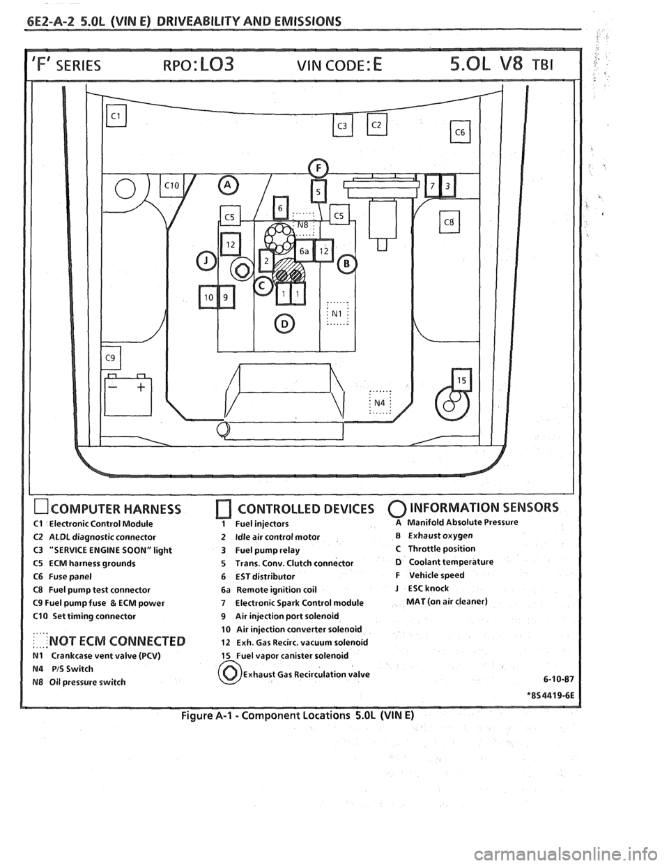
6E2-A-2 5.OL (VIN E) DRIVEABILIW AND EMISSIONS
IFf SERIES VIN CODE: E
OCOMPUTER HARNESS
C1 Electronic Control Module
C2 ALDL diagnostic connector
C3 "SERVICE ENGINE SOON" light
C5 ECM harness grounds
C6 Fuse panel
C8 Fuel pump test connector
C9 Fuel pump fuse & ECM power
C10 Set timing connector
....,
: . ... 'NOT ECM CONNECTED
N1 Crankcase vent valve (PCV)
N4 PIS Switch
N8 Oil pressure switch
[7 CONTROLLED DEVICES 0 INFORMATION SENSORS
1 Fuel injectors A Manifold Absolute Pressure
2 Idle air control motor B Exhaust oxygen
3 Fuel pump relay
C Throttle position
5 Trans. Conv. Clutch connector
D Coolant temperature
6 EST distributor
F Vehicle speed
6a Remote ignition coil
J ESCknock
7 Electronic Spark Control module MAT (on air cleaner)
9 Air injection port solenoid
10 Air injection converter solenoid
12 Exh. Gas Recirc. vacuum solenoid
15 Fuel vapor canister solenoid
Exhaust Gas Recirculation valve
6-1
0-87
Figure A-I - Component Locations 5.OL (VIN E)
Page 501 of 1825
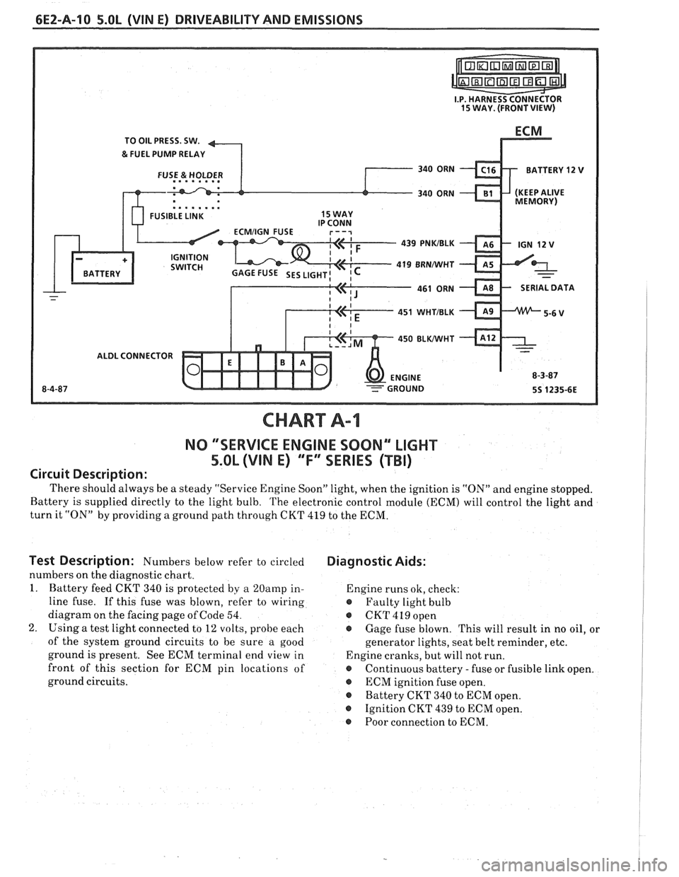
6EZ-A-10 5.0L (VIN E) DRIVEABILITY AND EMISSIONS
TO OIL PRESS. SW.
&FUEL PUMP RELAY
BATTERY
12 V
. . . . . . . . FUSIBLE LINK 15 WAY
439 PNWBLK
419
BRNNVHT
SERIAL DATA
451
WHTIBLK
450 BLWHT
ALDL CONNECTOR
NO "SERVICE ENGINE SOON" "LIGHT
5.OL (VIN E) "F'" SERIES (TBI)
Circuit Description:
There should always be a steady "Service Engine Soon" light, when the ignition is "ON" and engine stopped.
Battery is supplied directly to the light bulb.
The electronic control module (ECM) will control the light and
turn it "ON" by providing a ground path through CKT 419 to the ECM.
Test Description: Numbers below refer to circled
numbers on the diagnostic chart.
1. Battery feed CKT 340 is protected by a
20amp in-
line fuse. If this fuse was blown, refer to wiring
diagram on the facing page of Code 54.
2. Using a test light connected to 12 volts, probe each
of the system ground circuits to be sure
a good
ground is present. See ECM terminal end view in
front of this section for ECM pin locations of
ground circuits.
Diagnostic Aids:
Engine runs ok, check:
@ Faulty light bulb
@ CKT419open
@ Gage fuse blown. This will result in no oil, or
generator lights, seat belt reminder, etc.
Engine cranks, but will not run.
@ Continuous battery - fuse or fusible link open.
@ ECM ignition fuse open.
@ Battery CKT 340 to ECM open.
o Ignition CKT 439 to ECM open.
@ Poor connection to ECM.
Page 502 of 1825
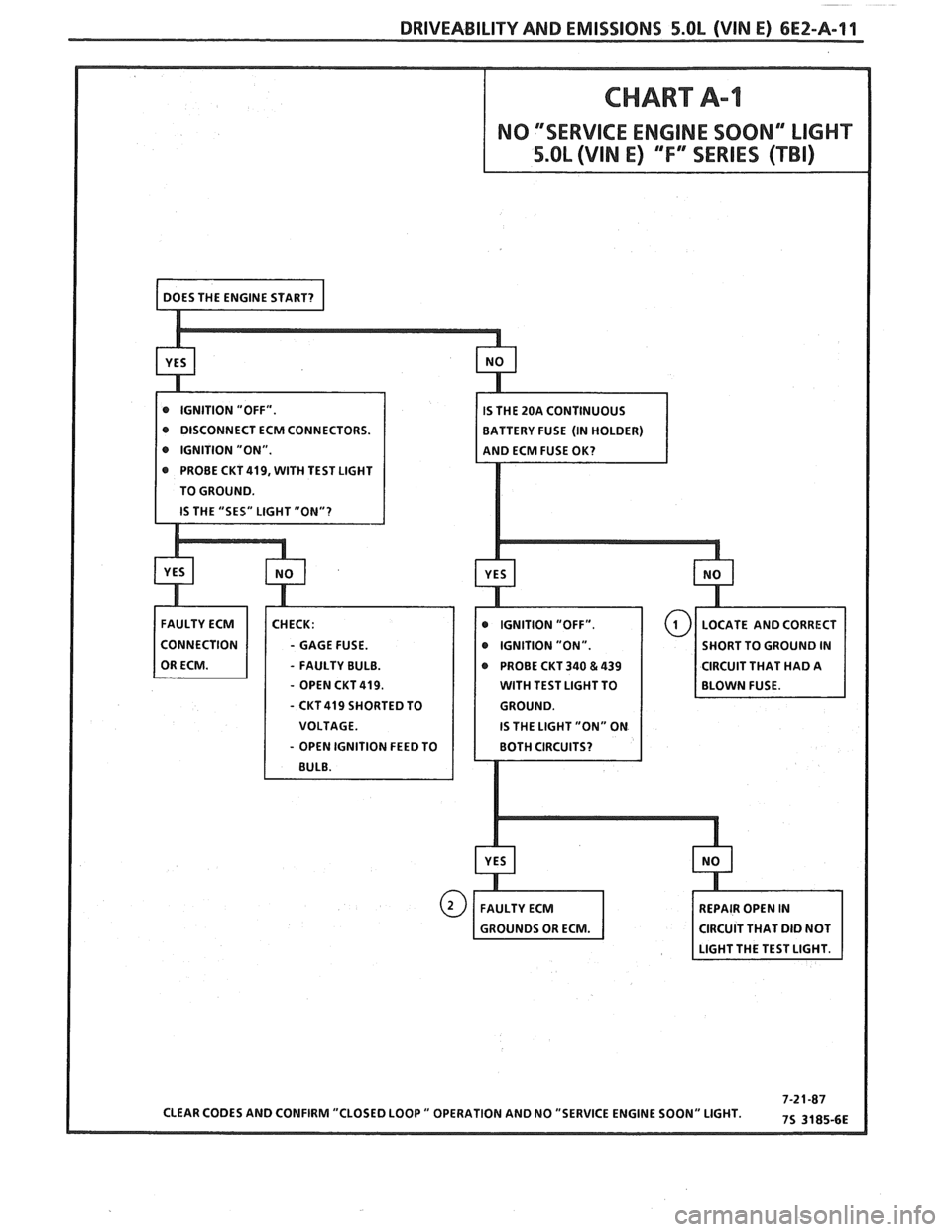
DRIVEABILITY AND EMISSIONS 5.OL (VIN E) 6EZ-A-11
@ DISCONNECT ECM CONNECTORS.
@ IGNITION "ON".
@ PROBE CKT 419, WlTH TEST LIGHT
TO GROUND.
- GAGE FUSE. IGNITION "ON". SHORT TO GROUND IN
- FAULTY BULB. 0 PROBE CKT 340 81 439 CIRCUIT THAT HAD A
- OPEN CKT 419. WITH TEST LIGHT TO
- CKT419 SHORTED TO